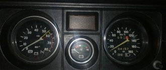
Car tachometer
is a measuring device that is designed to measure the number of revolutions of the engine crankshaft per minute (rpm). Previously, mechanical tachometers were installed in cars. Modern cars have electric or electronic tachometers.
While the car engine is running, the tachometer allows you to monitor the stability of its speed at idle and while the car is moving. The stability of idle speed can be used to judge the condition of the fuel supply system, ignition system and the engine itself.
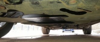
When setting the idle speed and adjusting the engine ignition timing using a strobe light, you cannot do without a tachometer. It is necessary to simultaneously make adjustments and monitor engine speed. After each tightening of the adjustment screw, it is inconvenient to look at the readings of the tachometer installed inside the car. A mirror installed in the cabin can help out, but this is also not the best solution. It is much more convenient to have a tachometer built into a strobe light.
When making a strobe light with my own hands, I mounted a tachometer into its body. When checking and adjusting the engine's OZ, this technical solution showed ease of use.
Analog tachometer circuits published on the Internet are distinguished by a greater error in readings; not every car enthusiast can replicate them made on digital microcircuits.
The tachometer circuit design we bring to your attention is distinguished by its simplicity and high accuracy of readings, regardless of changes in ambient temperature and supply voltage. It has an extended scale, which allows, when using a small-sized dial indicator, to measure the engine speed with high accuracy.
Tachometer malfunctions
Despite the fact that the TX-193 tachometer is considered quite reliable, it also has malfunctions. Their signs are:
- lack of response of the needle to changes in engine speed;
- chaotic movement of the arrow up and down, regardless of the engine operating mode;
- obvious underestimation or overestimation of readings.
What kind of breakdowns do the listed signs indicate?
The arrow does not respond to measuring the number of revolutions
Usually, the lack of response from the arrow is due to a broken contact in the connectors of the main wires of its connection, or damage to the wiring of the circuit. The first step is:
- Inspect the fastening of the conductor in brown insulation to terminal “K” on the ignition coil. If you detect poor contact, traces of oxidation, burning of a wire or terminal, fix the problem by cleaning the problem areas, treating them with anti-corrosion liquid, and tightening the fastening nut.
- Check the reliability of the connection of the black and white wire to the vehicle ground. If contact is broken, clean the wire and the surface to which it is attached.
- Using a tester, determine whether voltage is supplied to the red wire when the ignition is on. If there is no voltage, check the serviceability of fuse F-9, which is responsible for the integrity of the instrument panel circuit, as well as the condition of the ignition switch contacts.
- Disassemble the instrument panel and check the connections of the contacts in the tachometer wiring harness block. “Ring” all the wires going to the device with a tester.
Video: tachometer needle does not respond to engine speed
The tachometer needle jumps chaotically
Jumps in the TX-193 needle in most cases are also a symptom of malfunctions associated with its electrical circuit. The reasons for this behavior of the device may be:
- lack of good contact at the negative terminal of the battery;
- oxidation or burning of the brown wire on the ignition coil;
- burning or wear of the contacts of the ignition distributor cap or slider;
- wear of the distributor shaft bearing;
- shorting the red wire powering the device to vehicle ground;
- malfunction of the crankshaft position sensor (for injection engines).
A similar problem is solved by stripping the contacts, replacing the ignition distributor cap, slider, support bearing, restoring the integrity of the insulation of the device’s supply wire, and replacing the crankshaft sensor.
Video: tachometer needle jumps
The tachometer underestimates or overestimates the readings
If the device is outright lying, then the problem most likely lies in the ignition system. In other words, it shows correctly, but the number of pulses created by the chopper per revolution of the distributor shaft is more or less than four. If the tachometer readings are incorrect, there is usually a deterioration in engine performance. In this case, the speed may fluctuate, misfires periodically appear, which is accompanied by engine vibration and white or bluish exhaust.
In this case, the fault should be looked for in the breaker, or rather, in its contact group or capacitor. To fix this problem you need to:
- Disassemble the ignition distributor.
- Check the condition of the breaker contacts.
- Clean contacts.
- Adjust the gaps between the contacts.
- Check the serviceability of the capacitor installed in the breaker.
- Check the serviceability of the crankshaft position sensor. In case of malfunction, replace it.
However, the reason may be in the tachometer itself. Malfunctions occur related to the parts of the electronic board, as well as to the milliammeter winding. You can't do without knowledge of electronics here.
Incompatibility of the TX-193 tachometer with a contactless ignition system
Older models of TX-193 devices are designed exclusively for contact ignition systems. All owners of “sixes” who independently converted their cars to a contactless system subsequently encountered problems with the tachometer. It's all about the different forms of electrical impulses arriving at the device from the breaker (in a contact system) and the switch (in a contactless system). The simplest way to solve this problem is to install a capacitor in the cut of the same brown wire coming from the breaker. But here it is necessary to experimentally select the desired container. Otherwise, the tachometer will lie. So, if you have no desire to engage in such experiments, just buy a device for a contactless ignition system.
Video of a homemade tachometer working
Share useful diagrams
Such a power supply can power fairly powerful low-frequency amplifiers or adapt the unit to an ordinary 12-volt amplifier from the TDA series. In addition, the power supply can be supplemented with a voltage regulator and used as a switching laboratory power supply.
| DEVICES BASED ON ELECTRIC LIGHTERS
|
| POWERFUL POWER SUPPLY FOR UMZCH |
To power high-power audio amplifiers - from 0.5 kW and above, in order to reduce the size of the power supply, special switching power supplies are required. Let's take a look at the schematic diagram of such a device.
Automatic electronic timer for supplying water to the pool - circuit on a microcontroller for self-assembly.
How to assemble a table lamp based on a fluorescent tube and electronic ballast from a non-working energy saver.
Types of tachometers for outboard motors
Any tachometer works as a pulse counter in the engine's electrical system, which is directly related to the speed of its crankshaft.
Unlike a car engine, a boat tachometer most often receives information not from the ignition system, but from magdino coils (“dynamo + magneto”), which on outboard motors act as a generator.
The data obtained by the tachometer is recalculated and displays the value of the number of revolutions of the engine shaft per unit of time on the liquid crystal display screen or dial indicator.
Tachometers are classified according to several parameters and are:
- universal, that is, suitable for different types of engines;
- designed to work with a specific type of engine (two-stroke or four-stroke).
In addition, tachometers are divided into
- analogue, in which the engine speed is displayed on a dial indicator;
- digital, where information about the number of engine revolutions is displayed on a digital display.
Digital tachometers can additionally be combined with other measuring instruments, for example, a counter of engine hours that a boat engine has worked.
Microelectric Voltage Generated Machine
The tachometer generator converts the shaft rotation indicator into an electrical signal. Its operation uses the properties of the angular velocity of the rotor, the excitation flow, which is proportional to the generated EMF. Most modern tachogenerators are the permanent magnet type. These devices use a rotating joint, one end of which is connected to the machine shaft, inducing an electromotive force (voltage) proportional to the speed of the shaft. The armature contacts are connected to the voltmeter circuit, converting the voltage into a speed value.
These tachometers are distinguished by their accuracy, maximum permissible performance and operating temperature. Used as sensors in various automotive and electromechanical computer devices. Operate in AC or DC networks.
Installation of the device
Installing the device is not difficult; almost any user of a boat with a motor can do it. The device is mounted on the instrument panel or on the tiller motor, depending on the type of design.
Installing a tachometer includes the following series of actions:
- Choose a place to install the device.
- Decide on the length of the wires.
- When installing in the dashboard, prepare a hole of the required size (this can be specified in the instructions).
- Make or buy a wiring harness to connect the motor and the device. The wires of the proprietary harness have the appropriate connection diagram and suitable length, and are also equipped with moisture-protected connectors and cable lugs. Specialized components will simplify the installation process.
- Attach the tachometer in place using the mounting hardware.
The connection also has some features depending on the type of device design:
- For a tachometer without a power source, the cable must be connected to the magneto coils from which the pulses will be read.
- If the device has a power source, the spark plug wire is wrapped in connecting harnesses. The number of turns and the distance to the spark plugs are indicated in the instructions (usually 3-6 turns and a distance of 4 cm are sufficient). The tachometer terminals are connected to the harness.
The cable should not come into contact with moving or hot parts of the motor. Connections are made strictly according to the diagram. When the engine is properly connected and started, the device will begin to count the number of revolutions. You can adjust the displayed data using settings.
Exploitation
The simplest tachometer, made with your own hands on the basis of a calculator, works after soldering the contacts to the addition button of the computer.
Measuring the rotation speed is performed as follows:
- The micro calculator turns on.
- The “+” and “1” keys are activated synchronously.
- The gadget starts up and measurements are taken on it. To ensure accurate readings, the stopwatch should be turned on at the same time as the calculator.
- Wait 30 seconds and then look at the screen. The corresponding value should appear on it.
- This indicator is the number of revolutions in 30 seconds. Multiplying the number by two, we get the number of rotations per minute.
Review of popular models
Manufacturers of outboard motors, as a rule, do not make measuring instruments for them. This task is assigned to partner companies. For example, Teleflex Marine produces a large number of tachometers with the Mercury logo. At the same time, it also produces Osculati tachometers and branded Teleflex.
Also, a number of other companies (China, Taiwan) produce a large number of tachometers with Yamaha and Suzuki logos
Therefore, professionals suggest not focusing on the “native” brand of tachometer and, when choosing it, be guided by practical expediency
Let's look at several of the most popular models of tachometers for outboard motors:
Yamaha. The digital multifunctional tachometer 6Y8T-8350T-11-BK is housed in a waterproof housing. Designed to fit into a standard 86mm instrument panel hole and is used with Yamaha engines from F50 and above. The display shows the current and maximum engine speed, as well as the number of engine hours. The cost of the tachometer is 23,615 rubles.
Cost – 23615 rubles.
Mercury. Flagship analog tachometer (0-8000 rpm) is designed for installation on all Mercuri engines. It has a waterproof case with anti-fog glass, as well as a pointer dial. The price of the tachometer is 5620 rubles.
Price – 5620 rub.
Suzuki. Analog tachometer for DF9.9-30/DT25-40 engines – installed in a standard hole in the boat’s dashboard (86 mm). It has anti-fog glass and shows up to 7000 engine rpm. It does not have an operating mode selector, since all Suzuki DF/DT series engines are equipped with 12-pole generators. Its price is 4400 rubles.
Price – 4400 rub.
Price: 394.28 rub.
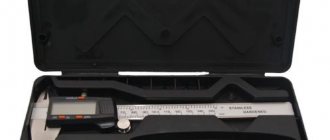
Increase speed, reduce fuel consumption, choose the optimal propeller - there’s no way without a tachometer. Of course, an experienced boater will say that he can determine engine speed by ear, but you shouldn’t believe him, it’s like in a joke: “Well, that’s what you say!” Inductive tachometer under the general name TC-011.
This option has an internal battery and a sealed non-separable (conditionally) case. The tachometer is inductive, i.e. does not require connection directly to the engine wiring. The length of the wire is 1 meter, we simply wind 5-6 turns onto the spark plug wire and set the tachometer to our type of engine (one or two pulses per revolution or one pulse per two revolutions).
People often complain about this tachometer model that it is not possible to count pulses from the spark plug wire, and then there is a recommendation to play with the number of turns and the length of the wire. However, my tachometer started up without any problems at 5 turns at 0.5 meters, and at 6 turns at 1 meter.
After the first turn on, the tachometer remains on all the time and displays the engine hour meter on the screen. You can forcefully turn off the tachometer by pressing and holding buttons S1 and S2, but then the engine hour meter will be reset. Switching between modes (tachometer or counter) occurs automatically; when the engine is running, the tachometer is displayed; after the engine is stopped, the hour meter is displayed.
The tachometer housing is glued together and is easy to disassemble. If desired, the internal battery can be easily changed. (in the picture the tachometer was filled with sealant by the author after disassembly; in the original the cover was glued with hot-melt adhesive). Upd. A CR2450 3V lithium battery with an approximate capacity of 600mAh is installed
Well, a small demonstration of the work (unfortunately, it is terribly hot and the camera did not allow us to film further, due to overheating) Overall: if you own a simple motor without brains, this is a must-have gadget for your household.
A tachometer is a device for measuring the rotation speed of engines, shafts, and other mechanisms. The tachometer has been used in transportation technology for more than a hundred years. As a rule, it is installed on the dashboard. The device indicates the rotation speed of the internal combustion engine during operation. In modern cars equipped with electronic engine control systems, it is not always installed. However, the tachometer readings allow you to select the most suitable driving mode. In some cases, this allows you to save fuel or, conversely, switch to a more aggressive driving style. Therefore, experienced car enthusiasts and professional drivers often install dashboards with tachometers on their own.
Let's look at how to independently connect a tachometer.
Tachometer
Add a link to a discussion of the article on the forum
RadioKot >Schemes >Digital devices >Measuring equipment >
| Article tags: | TachometerAdd tag |
Car tachometer with digital display.
Author: Tro-Sha Published 03/12/2007
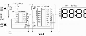
For those who want to pamper their old four-wheeled friend with a new trinket and warm their hands with a soldering iron, I offer a diagram of a tachometer that counts the electrical impulses occurring on the primary winding of the ignition coil (SC). The display readings are in thousands and hundreds of rpm. Limit - 9.9 thousand rpm
Pulses with an amplitude of 350-400V are removed from the short-circuit contact connected to a mechanical breaker or electronic switch. Since the spark formation process is oscillatory, only the first pulse of maximum amplitude must be passed to the tachometer input. For this purpose, use a zener diode VD1 with an opening voltage of about 100V. Capacitor C1 dampens high-frequency noise, and diode VD2 dampens negative voltage surges. The cascade on transistor VT1 is used to match the levels of input pulses with the logical levels of digital microcircuits. The signal from the VT1 collector triggers the standby multivibrator on the DD1 chip, which produces counting pulses of constant duration of approximately 3 ms, supplied to the counting inputs of the DD3 and DD4 chips. Counters DD3 and DD4 are included according to the standard synchronous direct decimal counting scheme. The information outputs of the counters are connected to the inputs of the binary code decoder into the positional code of the seven-segment digital indicator. To increase the brightness of the indicators HL1 and HL2, they are connected to decoders through buffer stages on transistors VT2-VT15. The DD2 chip contains an asymmetrical multivibrator that sets the measuring interval and controls the operation of the circuit. The duration of the positive pulse at point B is set by capacitance C2 and resistor R5 and is equal to 300 ms for use in a four-cylinder engine. The duration of the negative pulse at point B (positive at the output of element DD2.4) depends on C2 and R3 and is approximately equal to 3 ms.
At the beginning of the measurement cycle, the leading edge of the measuring pulse is differentiated by the C4R8 circuit and resets counters DD3 and DD4. Then a high logic level at pin 6 of the DD1 microcircuit allows the operation of the standby multivibrator and the passage of pulses to the inputs of the counters DD3 and DD4 until the end of the measuring pulse. A short negative pulse at point B is inverted by element DD2.4 and fed to pins 1 of microcircuits DD5 and DD6, allowing the writing of logical levels from the counter outputs to the decoder registers. After which the measurement cycle is repeated.
The power supply of the circuit is stabilized by the DA1 chip. C6 smoothes out voltage surges in a car generator, which can damage the stabilizer chip. VD4 - foolproof.
Design:
1. D817, due to its large size, is soldered into the gap in the wire going from the short circuit to the tachometer and insulated. (Instead of D817, you can use a neon light bulb). 2. DA1, C6 and VD4 are installed inside a U-shaped base made of thin aluminum with dimensions 75x52x25mm. Above them, separated by a cardboard spacer, is the main board. There is a cardboard shell around it all. 3. The indicators are located on a separate board connected to the main board with wires. 4. The printed circuit board is single-sided.
Wire jumpers are highlighted in blue. Conductors dedicated to electrical diagram in red, made with MGTF-0.2 wire from the solder side. C2 from the K73-17 series at 63V. It is better to adjust the tachometer using the frequency meter. By selecting R5, set the duration of the positive pulse at point B to 300 ms. Or apply a voltage of 50Hz 30:50V to the connection point between VD1 and R1 and achieve stable indicator readings of “1.5 thousand.” Note:
If multi-spark ignition is installed, the tachometer will lie like a gray gelding.
The second version of the tachometer is shown in the following diagram:
The difference from the first scheme is the use of indicators with a common anode and buffer stages on pnp transistors. In this regard, logical 1 signals are supplied to the control inputs S (pins 6) of microcircuits DD5 and DD6. Recommendations for design and configuration are the same as for circuit No. 1. The PCB drawing is shown below.
The third version of the tachometer is characterized by reduced energy consumption.
It uses IV-6 vacuum-luminescent indicators, which are connected directly to the outputs of K176ID3 decoders. The indicators are powered by a voltage converter based on the DA1 K157UD1 microcircuit and the TV1 transformer wound on a K10x6x4.5 ring made of 1000NN ferrite. The voltage converter circuit is taken from Radio magazine No. 3-1994 and recalculated for a supply voltage of 12V (I-5 turns of wire PEV-1-0.2, II-140 turns of wire PEV-1-0.1 with a tap from the middle, III- 25 turns of wire PEV-1-0.23). Structurally, the tachometer circuit is divided into two boards: a measurement board and a power board; shown below.
The voltage converter does not require adjustment and, if the parts are in good condition, starts working immediately. In the author’s version, capacitors of the K53-14 type are used as C6, C7 and C8. The DA1 chip practically does not heat up and does not need an additional heat sink. The method for setting up the measuring part of the circuit is similar to the previous options. The boards are located one above the other, separated by an insulating gasket and covered with a shell made of thin cardboard.
Questions, as always, go to the Forum.
| What do you think of this article? | Did this device work for you? | |
| 7 | 1 | 2 |
| 0 | 0 |
These articles may also be useful to you:
Optical tachometer
Tachometer for scooter with digital display.
Reasons for tachometer needle movement and floating speed
If it jerks regularly, then this clearly indicates some kind of problem inside the car.
You need to pay attention to the tachometer on the VAZ 21099 carburetor and carry out several actions
Check the light bulb, which is called the “check”. If this light is on, a full diagnostic will indicate an error. If the car does not have such a light bulb, then it will be even more difficult to determine the breakdown. The next step is to check the wiring. Many people only monitor contacts with a plus and minus sign, and later wonder why the tachometer on the VAZ 21099 does not work. In fact, you need to check not only the positive and negative wires, but also the quality of the contacts themselves. The most common reason for the tachometer needle to jerk is poor distributor contacts. If all of the above is in order, and the tachometer needle continues to jump, you need to start checking the ignition system. If the ignition system does not work well, the cause has been found. There may also be a situation where malfunctions in the tachometer appeared precisely after any parts in the car were replaced or disassembled
Now you need to check again whether everything is installed correctly. It is very important to pay attention to the position of the zero. If it is set incorrectly, then the toggle switch located on the back of the panel will help you set the required position. Checking the VAZ 21099 carburetor If the arrow continues to twitch strongly, then perhaps the switch is no longer functional
Checking the VAZ 21099 carburetor If the needle continues to twitch strongly, then perhaps the switch is no longer functional.
It is very important to constantly monitor the condition of your car and check the operation of all parts, as well as replace spare parts in a timely manner, since one part can lead to breakdown of the entire mechanism. Many people are interested in the question: why do the revolutions on the VAZ fluctuate? The most important answer: the cause is not always in the carburetor itself. Both the power supply system and the ignition system may well fail.
The tachometer should show all this
Both the power supply system and the ignition system may well fail. The tachometer should show all this
Many people are interested in the question: why?
Does the speed on the VAZ fluctuate? The most important answer: the cause is not always in the carburetor itself. Both the power supply system and the ignition system may well fail. The tachometer should show all this.
Symptoms of floating speed.
- The speed changes: either downward or, conversely, upward.
- Skips are observed.
- The plugs in the carburetor can be heard.
- Popping noises are heard in the muffler.
Reasons for floating turnover.
- The carburetor was adjusted incorrectly, which caused a malfunction on the tachometer.
- The next reason is a malfunction of the solenoid valve. You can check by removing and turning on the engine. If there is a click, the valve is working.
- Excess air entering the fuel mixture.
- Dirt in system channels and jets.
- If all of the above raises the question of why the VAZ idle speed fluctuates, you need to check the VAZ 2109 air filter. And don’t forget to keep an eye on the tachometer needle.
By following these recommendations, you can keep your car in order.
What does a tachometer do?
Its work is based on reading crankshaft revolutions. This is necessary in many life situations. Experienced car owners may argue that it is of no use on the VAZ 2105. This is fundamentally wrong. It’s enough to imagine a situation where you can’t hear the engine running due to noise on the street or loud music in the cabin. You can drive based on the speedometer, but what if the car, for example, is heavily overloaded or has a trailer? To put it briefly, you can make a list of tachometer functions.
- Determining the optimal moment for changing gears.
- Detection of floating revolutions.
- Determination of surges and maximum torque.
- Idle speed adjustment.
- Helping beginners learn how to drive a car.
- Ease of use in noisy environments.
- Early detection of engine or electrical problems.
- Reduces engine wear and saves fuel thanks to timely gear changes.
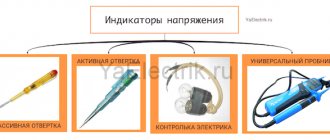
How the counter works
The remote mini frequency meter/tachometer/pulse counter is very simple and takes into account what the phototransistor sees after being reflected from an object illuminated by an infrared emitting LED (the IR diode is only activated at the moment of counting). You can make the circuit almost entirely on a microcontroller without using an op-amp, but it was decided to use an op-amp to increase the sensitivity of the device. The base is a modified and simplified version of the heart rate monitoring unit.
In mode “1”, it is enough to bring the front part of the counter to the tested area and wait for the signal to stabilize. The measurement lasts 0.5 s, and if it is identical in at least two consecutive measurements, then the program displays the result by cycling the digits on the display separating each digit with a short blanking.
Due to the simplification of the operation and reduction of measurement time, the result always becomes even - the program multiplies it by 2, which will allow the result to be calculated “per second”. Despite this rounding, the results are surprisingly accurate and the possible measurement error is relatively small. In practice, the frequency was measured in the range of up to 40 kHz, and it copes with this without problems.
As soon as we read the result and want to measure something, briefly press the button and measure again. But when we hold the button, we exit the current mode and switch to another.
In pulse counting mode “2”, measurement begins immediately after confirming the mode (short press of the button). A second press stops the measurement and displays the result. Reset is a second press that starts the next counting cycle. At this point, you can hold the button longer and return to mode selection mode.
Construction and details
Since the circuit is simple, I did not develop a printed circuit board. All parts, except the milliammeter, were installed on a universal breadboard measuring 30 mm×50 mm. The photo shows how the elements of the circuit are placed.
A three-pin connector is used to supply the supply voltage and input signal. The milliammeter scale is printed on a printer and glued on top of its standard scale.
The board with the parts is secured in the cover of the strobe housing with screws. The milliammeter is installed in a rectangular window cut out in the housing cover and secured with silicone.
This design for placing the tachometer provides easy access to the strobe board; just remove the cover and disconnect the connector.
Schematic parts list
- Microcircuit - Arduino
- Resistors – 33k, 270 ohm, 10k potentiometer
- LED element - blue
- IR LED and Photodiode
- 16 x 2 LCD screen
- 74HC595 shift register
Here, instead of a slot sensor, an optical one is used - reflection of the beam. This way they don't have to worry about the thickness of the rotor, the number of blades won't change the reading, and it can read the drum revolutions - which the slot sensor cannot.
So first of all you will need an IR emitting LED and a photodiode for the sensor. How to assemble it is shown in step-by-step instructions. Click on the photo to enlarge the size.
- 1. First you need to sand the LED and photodiode to make them flat.
- 2. Then fold the strip of paper sheet as shown in the picture. Make two such structures so that the LED and photodiode fit tightly into it. Connect them together with glue and paint them black.
- 3. Insert LED and photodiode.
- 4. Glue them together with superglue and solder the wires.
Resistor values may vary depending on which photodiode you are using. The potentiometer helps to reduce or increase the sensitivity of the sensor. Solder the sensor wires as shown in the figure.
The tachometer circuit uses a 74HC595 8-bit shift register with a 16x2 LCD display. Make a small hole in the housing to fix the LED indicator.
Solder a 270 ohm resistor onto the LED and insert it into pin 12 of the Arduino. The sensor is inserted into a cubic tube to give additional mechanical strength.
That's it, the device is ready for calibration and programming. You can download the program from this link.
Classification by operating principle
- Mechanical or electromechanical tachometers with direct drive. The revolutions are transmitted to the dial indicator through a flexible shaft, which, through a worm gear, receives rotation directly from the crankshaft or one of the transmission shafts. The operating principle of the indicator is based on the phenomenon of eddy current induction. The operation and design of a magnetic tachometer are extremely similar to the operating principle of a car speedometer. In modern cars, a similar tachometer design is not used.
- Electric machine. A distinctive feature is the connection to a generator. It is used primarily on diesel engines, but for the purpose of unification, a device of this type can also be used on gasoline engines.
- Electronic. The signal can be taken either from the ignition system or directly from the computer. Installed on gasoline and diesel internal combustion engines.
Design and principle of operation
Main components of electric machine and electronic tachometers:
- measuring unit, or signal converter. It can be based on elements of analog circuitry or built using special microcircuits;
- display unit with analogue or digital display of the number of revolutions;
- auxiliary elements.
Connection diagram
When looking for the reason why the tachometer does not work, it is first of all important to understand the connection diagram and the type of signal. There are 3 typical connection schemes:
- to a contactless ignition system (the tachometer wire is connected to the primary circuit of the ignition coil). The operating principle is based on measuring the frequency of voltage surges in the primary circuit of the ignition system. Calculating the ignition angle is impossible without focusing on the number of crankshaft revolutions, therefore the sparking frequency directly depends on the crankshaft rotation speed. On 4-cylinder internal combustion engines, a full revolution of the crankshaft corresponds to 2 voltage pulses in the primary circuit. Accordingly, the higher the crankshaft rotation speed, the greater the frequency of voltage surges;
- connection to the contact ignition system. The operating principle and connection diagram are similar to the BSZ, but the design of the measuring unit will differ depending on the voltage of the input circuit;
- connection to the engine ECU. The principle of operation is still based on recording voltage pulses in the primary circuit of the ignition system, but the signal to the tachometer comes from the engine control unit;
- connection to the generator (the tachometer signal contact is connected to terminal W of the generator). The rotation of the generator pulley is carried out by a belt drive from the crankshaft, so the rotation speed of the generator rotor will always be proportional to the crankshaft speed. The change in the number of revolutions of the crankshaft can be calculated by constantly measuring the amount of EMF generated on the winding. According to its principle of operation, an electric machine tachometer resembles a regular one class=”aligncenter” width=”448″ height=”412″
Typical faults
If the mechanical tachometer on a car stops working, there is mechanical damage to any of the structural elements. A broken cable of a flexible shaft, wear of the worm gear elements, the appearance of backlashes, deformations - all these reasons can cause the engine speed indicator to fail.
What to pay attention to if the electronic tachometer does not work:
wiring integrity
In this case, it is important to check not only the signal wire, but also the ground and power supply of the instrument panel; quality of contacts. The presence of oxides and loose contact inside the chips may well cause the tachometer to fail; the integrity of the elements of the measuring unit, which are located behind the protective glass inside the dashboard
Among mechanical damage to transistors, burnout of microcircuits, tracks or swelling of resistors, the most common reason for a non-working tachometer is a violation of solder integrity. For example, on the Mitsubishi Padjero II, the appearance of microcracks in the soldering areas of the tachometer elements is a generally recognized disease.
DIY electronic tachometer
With the wide possibilities of the electronics market, it is not difficult to make a tachometer circuit at home using a multimeter. Moreover, the results obtained in such circuits are accurate in assessing the overall operating condition of the system being measured.
Circuit diagram using IC 555:
- The pulse is taken out from the scooter's spark plug and fed to the end of R6.
- The transistor responds to impulses in accordance with triggers.
- The transistor activates monostability with each incoming pulse.
- The monostable remains on for a certain moment, and when triggered, generates an average on-time output that is directly proportional to the average startup speed.
- The capacitor and resistor at the output of the IC combine the result so that it is directly read by a 10V voltmeter.
- R3 is adjusted so that the output generates an accurate interpretation of the RPM feed rate.
The above adjustment is made using a conventional tachometer. Parts for manufacturing are widely available and can be purchased at any radio supply store. List of parts for the homemade version:
- R1 = 4K7.
- R2 = 47E.
- R3 = 100 KB, may be variable.
- R4 = 3K3.
- R5 = 10K.
- R6 = 470 K.
- R7 = 1K.
- R8 = 10K.
- R9 = 100K.
- C1 = 47n.
- C2 = 100n.
- C3 = 100n.
- C4 = 33uF / 25V.
- T1 = BC547.
- IC1 = 555.
- M1 = 10V FSD meter.
- D2 = 1N4148.
- C5 with any value between 3.3uF and 4.7uF.
Before you make a tachometer with your own hands, you need to complete the installation documentation. A simple circuit designed using readily available elements with a rubberized MOC7811 opto-isolator module and two seven-segment displays measures disk speed in RPS. This circuit calculates RPS from 00 to 99; if larger values are needed, another decade counter is added.
The circuit diagram contains IC555, MOC 7811, IC CD4081, IC CD4069 and IC 4033 and a seven-segment LTS 543 display unit. On the first timer IC 555, configured as a monostable multivibrator, it generates a clock pulse when switch S2 is pressed, green LED 1 indicates the detection time .