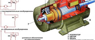
Classic connection options
Most emails Motors for modern electric drives operate from an alternating three-phase line (each of the three phases is supplied by a separate conductor). Accordingly, the terminal box contains the terminals (input and output) of three windings. They can be connected to each other and to the network using two classic schemes: “star” and “triangle”.
Star and Delta connection diagram
For the first, a characteristic feature is the closure of the end terminals of each coil to one point (in practice, this is one neutral). Meanwhile, the mains voltage is supplied to the input pins. This scheme is characterized by a softer ride, but unfortunately, it does not allow you to develop full power.
The second option with a triangle is characterized by a serial connection of the terminals of the windings: the end of the first is connected to the beginning of the second, etc. This starting option guarantees achievement of the rated power, but during switching on, large currents may arise that can thermally damage the winding terminals.
If you remove the terminal box cover, both connection options will look like this:
Conditions for connecting an electric motor
The main condition for the normal operation of three-phase motors is the stability of voltage and current in each phase of the electrical network. A break in at least one phase will result in the engine losing a significant part of its power and, when the load on the shaft exceeds 50% of the standard value, it will stop and fail. Starting in two phases is possible only in the complete absence of load and only at a time when the rotor maintains at least a small angular speed.
Asynchronous motor
For your information! At the moment of starting, an asynchronous motor consumes a current that is 3-5 times higher than the rated current until the rotor reaches a certain speed. This phenomenon comes from the operating principle of the engine.
Thus, if in operating mode the motor current allows the use of conventional circuit breakers, then to ensure normal starting, switching should be done through a powerful contactor (magnetic starter).
Magnetic switch
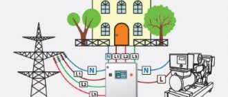
In some cases, it is possible to connect a three-phase motor to a single-phase household network. At the same time, power characteristics drop significantly. This situation arises very often when it is necessary to use an industrial drive in a domestic environment. Using a special switching circuit, they ensure normal operation of the motor, taking into account the reduction in power.
Application of magnetic contactor
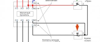
To organize a soft start, it is necessary to introduce a special switching device - a starter - into the power circuit. This is one of the connector options that can be supplemented with optional elements, for example, a thermal relay. A huge advantage of this scheme is the possibility of organizing not only the start-up of electricity. the engine, but also stopping it, reversing it, as well as protecting connections from damage by excess currents. In addition, the core or coil can have a voltage rating of 380 or 220V, which allows you to connect the motor to a power and household network.
Classic electrical circuits for connecting motors through a starter can be divided into two types:
- Irreversible. Connection of the unit and the network without the need/possibility of organizing its reverse movement. In this case, it is possible to integrate both into a power and household (220V) network,
Non-reversible connection diagram
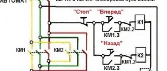
- Reversible. An electrical circuit that combines two starters (unit) with a circuit breaker. It is also possible to change the direction of rotation of the rotor assembly for power and household (220V) networks.
Reversible connection diagram
As you can judge from the illustrations, the differences between the “network” options lie in the connection points of the contactor terminals:
- for 380 volts the contacts are closed on 2 of 3 phases,
- for 220 volts, one of the contacts is connected to the extreme phase, and the second to zero.
Thermal relay
In addition, in all four options there is an element designated as “P”. This is nothing more than a thermal relay. It is connected in series with the contactor coil and serves to protect the motor from excessive current loads.
According to the principle of operation, the thermal relay is a key, that is, when critical current values for the operation of the unit and contactor are reached, a temporary break in the power supply occurs. Some types of thermal relays or “thermal relays” are used for DC circuits or specific modes (delayed start-up, phase failure, etc.).
Constant activation of the magnetic starter leads to mechanical wear of the contacts, which a thyristor or contactless circuit does not have. The circuit is broken not mechanically (dividing the contact group), but electronically - due to diode bridges.
Reconnection from 380V to 220
To connect a three-phase motor to 220 volts, it is important to know that it has six terminals that fully correspond to several windings. Using a wire tester, a ring is made to search for the coil. The ends are combined in pairs to form triangles.
First of all, several ends of the network wire are connected to several ends of the resulting triangle. The unused end is attached to the capacitor, while its free wire is also connected to the end of the coils, as well as the network wires.
The choice of option determines exactly where the motor will rotate. Having completed the necessary steps, the motor is started after supplying 220 volts to it.
If a hum is observed during the connection process, but the engine does not spin, a capacitor must be installed, which causes the motor to spin during the startup process, as in the photo of connecting an electric motor on the website.
Resistance is measured using a tester. If it is not available, you can use a battery or a light bulb designed for a flashlight: certain wires are connected directly to the circuit with the lamp.
If the ends of the winding are found, the light bulb lights up. It is much more problematic to determine the ends, as well as the beginning of the windings. In this case, a voltmeter is needed.
When the battery and wire break, it is important to look to see if the needle deviates. Similar actions must be carried out with other windings in order to change when polarity is achieved. The needle deflects to the original measurement.
Operation of devices with a specific moving part
The usual version of the rotor assembly of a three-phase asynchronous electric motor is a short-circuited “squirrel cage” type, which is assembled from steel plates. When there is a need to reduce the rating of starting currents with the ability to regulate the rotation speed, then a wound rotor is used. Its characteristic feature is two groups of conclusions:
- Stator. Classic terminal block to which mains voltage is supplied (380 or 220V),
- Rotary. Additional terminal block for the terminals of the wound rotor windings, to which the contacts of the rheostat (resistance block) are connected.
The latter is necessary for a smooth start with gradual switching on/off of individual resistances in the wound rotor winding circuit.
Connecting a three-phase motor
This means an asynchronous electric motor, winding connection - star or triangle, connection to a 380V network.
For the engine to operate, the working neutral conductor N (Neutral) is not needed, but the protective conductor (PE, Protect Earth) must be connected for safety reasons.
I have already written in detail about the principles of constructing 380V networks in articles about a three-phase meter and voltage relay.
Other related articles – Difference between three-phase and single-phase voltage, Grounding systems.
In the most general case, the diagram will look like this, as shown at the beginning of the article. Indeed, why not turn on the engine like a regular light bulb, only the switch will be a “three-key”?
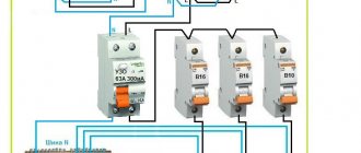
2. Connecting the engine through a switch or circuit breaker
But no one even turns on a light bulb just like that; the lighting network and, in general, any load is always turned on only through circuit breakers.
Read more about replacing and installing circuit breakers here. And about their parameters and choice – here.
Operation of DPT type P 41
An electric machine, powered by 220 V DC, has a more complex design compared to the units described above. The specifics of operation, for example, of the P 41 model, require the presence of a commutator-brush assembly, an armature coil, and auxiliary stator (inductor) poles. Motors of this model size belong to machines with an electromagnetic inductor. That is, to connect and start P 41, it is not permanent magnets that are used, but an independent or mixed excitation winding of 110 or 220V.
As you can judge, the operation of three-phase (380 V) and single-phase (220 V) AC machines or DFC type P 41 can be organized in a variety of ways, from classical to specific ones, taking into account actual operating conditions.
Electric motor connection options
Most often, connecting an electric motor at 220/380V with an existing capacitor is used, through which the power is reduced. The capacitor contact should be connected to zero, while the other should be connected to the next output of the motor. The result is a device with minimal power.
With increased power, a starting capacitor should be added to the existing circuit. When connected single-phase, it announces the third output.
As for the method of connecting an asynchronous electric motor, it is simply connected with a triangle, as well as a star. Such units have several windings. To change the existing voltage, you cannot do without swapping the outputs that go to the top of the connections.
When connecting such motors, it is important to read the instructions and certificate, since in imported versions you can often find a triangle that is suitable for domestic 220 volts. Such engines, if you are not careful about this issue and are connected with a star, immediately burn out.
With a power reaching more than 3 watts, it is not recommended to connect the motor, as this may cause a short circuit and damage the RCD.
Electric motors: design and principle of operationApplication of electric motors
- Electric motor rotor - design features and operating principle of the device. Repair and restoration instructions
Single-phase asynchronous electric motor
If we leave a short-circuited coil on the rotor and one coil on the stator, we will get an amazing design - an asynchronous single-phase motor.
At first glance, it seems that such an engine should not work. After all, there is no current in the rotor , and the magnetic field of the stator does not rotate. But if you push the rotor by hand in any direction, the engine will start! And it will rotate in the direction in which it was pushed at launch.
The operation of this motor can be explained by imagining the stationary alternating magnetic field of the stator as the sum of two fields rotating towards each other. While the rotor is stationary, these fields balance each other, so a single-phase asynchronous motor cannot start on its own. If the rotor is set in motion by an external force, it will rotate in parallel with one vector and towards the other.
A passing vector will pull the rotor along with it, a counter vector will slow it down.
It can be shown that due to the difference between the head and tail speeds, the influence of the tail vector will be stronger, and the engine will operate in asynchronous mode.
Diagram of connecting a three-phase motor to the network via a circuit breaker
Therefore, in more detail, the general case will look like this:
3. Connecting the motor via a circuit breaker. PRACTICAL SCHEME
Diagram 3 shows a circuit breaker that protects the motor from overcurrent (“rectangular” bends in the supply lines) and from short circuits (“round” bends). By circuit breaker I mean a regular three-pole circuit breaker with a load thermal characteristic of C or D.
Let me remind you that in order to approximately select (estimate) the required thermal current of the thermal protection setting, you need to multiply the rated power of the three-phase motor (indicated on the nameplate) by 2.
Circuit breaker for turning on the electric motor. The current is 10A, through which you can turn on a 4 kW motor. No more and no less.
Scheme 3 has the right to life (due to poverty or ignorance of local electricians).
It works great, just as twisting copper and aluminum can work for many years. And one “fine” day the twist will burn out. Or the engine will burn out.
If you use such a circuit, you need to carefully select the current of the machine so that it is 10-20% greater than the operating current of the motor. And select the characteristic of the thermal release D, so that during a difficult start the machine does not trip.
For example, a 1.5 kW engine. We estimate the maximum operating current - 3A (real operating current may be less, we need to measure it). This means that the three-pole circuit breaker must be set to 3 or 4A, depending on the starting current.
The advantage of this motor connection diagram is the price and ease of execution and maintenance. For example, where there is one engine, and it is turned on manually for the entire shift. The disadvantages of such a scheme with switching on via an automatic machine are:
- Inability to regulate the thermal current of the machine. In order to reliably protect the engine, the shutdown current of the circuit breaker must be 10-20% greater than the rated operating current of the engine. The motor current must be periodically measured with clamps and, if necessary, the thermal protection current must be adjusted. But a regular machine does not have the ability to adjust (.
- Inability to remotely and automatically turn on/off the engine.
These shortcomings can be eliminated; the diagrams below will show how.
Connecting a three-phase motor via a manual starter
A manual starter or automatic motor is a more advanced device. It has “Start” and “Stop” buttons, or an “On-Off” knob. Its advantage is that it is specially designed for starting and protecting the engine. The start is still manual, but the operating current can be adjusted within certain limits.
4. Connecting the motor via a manual starter. PRACTICAL SCHEME
Since motors usually have a high starting current, motor circuit breakers (automatic motors) usually have a thermal protection characteristic of type D. That is it can withstand short-term (starting) overloads of approximately 10 times the nominal value.
Manual motor starter with additional control contact.
Here's what's on the side:
Motor circuit breaker - characteristics on the side wall
Setting current (thermal) – from 17 to 23 A, set manually. Cut-off current (trigger during short circuit) – 297 A.
In principle, a manual starter and an automatic motor are the same device. But the starter shown in the photo can switch the power supply to the engine. And the automatic motor constantly supplies power (three phases) to the contactor, which, in turn, switches the power to the motor. In short, the difference is in the connection diagram.
The advantage of the scheme is that you can adjust the thermal current setting. The disadvantage is the same as in the previous scheme - there is no remote activation.