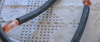
Connecting wires
To ensure full electrical conductivity, the integrity of the wiring is an important point. Damage or poor-quality adhesion is unacceptable.
It is important to ensure tight contact contacts and reliable connections in the “electrical node” areas. There are certain methods for eliminating cable breaks.
Among them, welding should be noted. It applies to copper and aluminum wires. This ensures a particularly reliable grip.
Connections can be divided into types:
- twist;
- welding;
- soldering;
- pressure testing;
- terminal blocks;
- self-clamping terminal blocks (WAGO terminals);
- PPE caps;
- bolt clamp.
The most complete connection for wires made of copper is soldering. It can be easily accomplished using flux (rosin, borax) and tin solder. Terminal blocks are also used - a special device that is made using screw terminals. They are selected separately in accordance with the cross-section of the cores.
Self-clamping terminal blocks are often used to save time on electrical installation work. In order to isolate a twisted or soldered electrical connection, PPE insulating caps are used. Today in the energy sector, WAGO terminals are widely used, which are produced for wires and cables of various diameters. In addition, WAGO terminals allow you to connect conductors made of different materials (copper and aluminum).
The choice of which connection to use depends on various factors:
- material (steel, copper, aluminum);
- number of twisted elements;
- section;
- place of work (house, street, in the ground, etc.).
Copper and aluminum connection
Often a situation arises when it is necessary to connect a copper conductor to an aluminum one. Since the chemical properties of copper and aluminum are different, direct contact between them, with access to oxygen, leads to oxidation. Often even copper contacts on circuit breakers are susceptible to this phenomenon.
An oxide film forms, resistance increases, and heating occurs. Here we recommend using 3 options to avoid this:
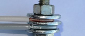
- bolt + nut with steel washers
They remove direct contact between aluminum and copper. The connection occurs through steel.
- special Wago terminal blocks with paste
The contacts are separated from each other in separate cells, plus the paste prevents the access of air and prevents the oxidation process from developing.
- use of copper-aluminum adapter sleeves GMA
How to connect electrical wires with lugs
Another way is to use tips. The tip looks like a piece of tube, cut and turned flat on one side. A hole for a bolt is drilled in the flat part. The lugs allow you to connect cables of any diameter in any combination. If it is necessary to connect a copper cable to an aluminum cable, special lugs are used, in which one part is copper and the other is aluminum. It is also possible to place a washer, brass or tinned copper, between the tips.
The ferrule is pressed onto the cable using a crimper, similar to how wires are connected using crimping.
Welding
Another way to improve twisting is welding. Again, welding is just a method of increasing the reliability of twisting.
It is not applicable for aluminum wires; welding is used only on large-section copper cables.
Reliability when welding is much higher than when soldering. It is a good way to improve connections in a junction box, but welding is still not very practical.
In addition, it will require special equipment, a welding inverter.
Welding is not used on aluminum wiring; an additional disadvantage is the possibility of weakening the twist, since when the wires are very heated, which will be necessary during the welding process, the twist itself may weaken due to a change in the physical properties of the metal.
Soldering and welding cannot be considered separate connection methods; they only provide additional reliability.
Also, after using a soldering iron or welding machine, the connection point will still have to be insulated.
Options for twisting stranded wires
In practice, 3 methods of twisting flexible stranded wires are used. The choice of method is made according to the situation and based on the preferences of the master. The methods are:
- serial connection;
- parallel connection;
- thin wire bandage;
Serial twisting
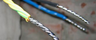
The stripped wires are applied to each other so that they form a crosshair. Then the conductors are twisted together. The connection made is symmetrical relative to the crosshairs. The ends of the wires stick out in opposite directions. After twisting, it is advisable to slightly tighten it so that it tightens.
The method is good due to the compactness of the resulting connection. Its thickness does not exceed 3 diameters of the insulated wire. Care must be taken. If the twist is protected from moisture by a heat-shrinkable tube, then the insulation is put on the core before making the connection.
Parallel
The insulation is removed from the ends of the wires. The cores should be connected so that the stripped sections are parallel. The ends of the wires point in the same direction. The current conductors are then wound onto each other in a spiral shape
It is important to make the connection as tight as possible, but not to break the conductors with excessive force
This twist can be found in the junction box. To protect the contact, electrical tape or heat shrink is used. For temporary and non-essential connections, it is allowed to use a PVC pipe (cambric) for insulation.
Bandage twist
The banded connection of cores is suitable for connecting thick wires that are difficult to bend with your hands or pliers. Current-carrying conductors are laid next to each other. They must first be properly cleaned on all sides using a needle file or file. Then the bare wires are tightly wrapped in a circle with the maximum number of thinner wires. A similar connection is used on power transmission towers.
Important! Do not connect the cable cores in a knot. The contact will be maximally tensile strength, but extremely unreliable in terms of electrical conductivity
What is PUE
Pue is a collection of regulatory documentation for the design and installation of electrical circuits; in fact, it is a desktop Bible for all people who begin to engage in electrical work. The collection shows the basic principles of creating circuits, the rules for their calculation, protection and communication devices. Further, all descriptions of electrical devices will be in accordance with the rules according to the PUE.
Selecting the cross-section and brand of wire
To lay electrical wiring in rooms and connect wires in a junction box according to the PUE, the conductors must have a different color insulating coating, from the same manufacturer with the same color scheme. For wiring, it is best to use VVGNG wire - a single-core copper wire, flat, double insulated, best with the additional designation NG, which means non-flammable. It is best to purchase wires from a well-known brand of the manufacturer; they must have a certificate. There is no need to take a wire without markings; wiring in the house is, first of all, safety and is done for more than one year, so saving is inappropriate here. It must be taken into account that a copper wire with the same cross-section can withstand one and a half times more load than aluminum.
Attention! For a capital circuit, you cannot use stranded wire PVS or SHVVP. Although these wires are soft and more convenient to lay, they have a higher current resistance, and accordingly they will heat up more when a load is connected.
Power calculation
One of the basic rules for calculating the cable cross-section: it is used in the calculation of 1 sq. mm of 9 A. electric current, that is, a cable with a cross-section of 1 mm can withstand the load of a kettle or iron with a power of 2 kW. Based on these recommendations, at least the following should be used for wiring in the house:
- lighting core is 1.5 mm square, which corresponds to 10 - 12 A.;
- sockets in rooms are 16A, which corresponds to a cross-section of 2.5 mm. sq.
- kitchen electric ovens, the wire for which must withstand 25A. – this is a 4mm section. kv;
- The core of a four-burner electric stove must withstand 32A. – cross section 6 mm 2. The correct choice of connecting electrical wires in the junction box depends on the cross-section of the wire.
Attention! You cannot use wires from different manufacturers, as they have different specific (ohmic) resistance per 1 linear meter.
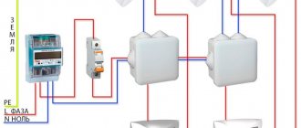
Electrical junction box and wire connection
After laying the wires, according to the drawn up diagram, they must be connected to each other. In order for the connection to be in one place, there are communication boxes (distribution boxes). Depending on the installation, device connections can be round or square, deep or shallow, and are divided into internal or external according to the method of fastening. According to the requirements of the PUE, the wires must pass at least 15 cm from the ceiling, taking into account all canopies. At the same distance, a device for switching cable cores is also attached. To install the internal box, a niche corresponding to the outer diameter of the sleeve is drilled in the wall; for external mounting, it is made directly to the wall.
Methods for connecting cable cores in a junction box
Methods for connecting power cable cores to each other in the distribution cavity depend on the specific situation, which takes into account:
- The metal from which the cores are made;
- External operating environment;
- Number of connected cores;
- Section of the connected cores;
For example, connecting by twisting, soldering, welding only a core made of the same metal (all PUE methods are prohibited); terminal clamps are used to connect wires made of different materials (copper, aluminum, steel, composite).
The connection can also be made in the following way: terminal blocks with bolt or spring clamps, Wago clamps; PPE clips (self-insulating); crimping with sleeves, bolted connections or a “Walnut” type clamp.
Terminal block
consists of screw terminals installed on one plate for each individual cable, which are mounted in plastic housings. There may be two or more clamps. The stripped cable core is inserted into the hole at the end of the housing and clamped with screws. Terminal blocks for connecting wires in the distribution box allow you to connect different diameters and cable materials. However, it has a drawback: approximately once a year a preventive inspection and tightening of the clamp screws is necessary. So - as the current passing through the contact heats up and the threaded clamp gradually weakens. Such blocks can be used when connecting a low-current network, for example, installing lighting or backlighting.
Walnut connection
This type of switching is a steel plate with screw fastening at the edges. The principle of operation is an ordinary threaded clamp of the bare core of the power cable with the possibility of branching with a smaller cross-section. The steel clamp is housed in a round carbolic (thermoset rubber) housing. The design is quite reliable and has been tested for many years of operation. Requires constant prevention at least once a year.
One of the most common disadvantages of threaded connections is loose contact in the terminals for connecting wires in the junction box, eliminating spring-loaded clamps or lever devices. One of the most famous and popular devices is the Wago eccentric clamp. The Wago device is designed in such a way that the clamping is performed by a lever with an offset axis. When the lever is turned inward, the eccentric securely clamps the end of the wire. Eccentric clamps are very easy to use and reliable in operation. In addition, the ends of power cables made of different materials and slight differences in diameter are reliably connected.
You can learn more about the types of terminal clamps from the video:
Spring clamps are also very popular
the principle of operation of such a device is clear from the figure: when you press the key, the lever presses the contact with the terminal, forming a cavity into which the end of the protected core is inserted. Unlike contacts that are clamped with screws, spring contacts clamp the ends quickly and reliably and there is no need to tighten them with a screwdriver from an awkward position. In such devices, it is very important to comply with the requirements of the electrical wiring in the junction box and the maximum current load for which the contact is designed (the value is written on the case). Exceeding the maximum permissible current in the contact will cause it to heat up, which will change the properties of the spring steel, which can weaken with all the ensuing negative consequences.
Self-isolating caps (PPE)
Another simple and quick joining method is self-insulating caps, or (PPE). This device is available in five standard sizes with a cross section of 1.4 mm. up to 5, 6mm. They are easy to use: just first twist the wires to be connected, then select a cap of the appropriate diameter and screw it onto the prepared twist. The cone spring inside the cap additionally twists the wires and compresses them together. The advantages of such a connection point are speed, but you should not trust the main network to such a device. When connecting the wires in the junction box correctly, it is best to use a more reliable method.
Joint with a sleeve
Another method of switching wires in an electrical distribution box is to connect the wires by pressing them into a connecting sleeve. This method is more reliable than twists and connecting caps. Clamping done correctly in this way is more reliable and simpler. The principle is carried out by inserting the stripped ends on one side of the sleeve or the opposite sides into a pre-prepared metal tube (brass or copper sleeve). Why is a metal tube clamped with a special device, reliably connecting the wires together? The metal sleeve is insulated either with a heat-shrinkable tube or with insulating tape with an overlap of half the width of the tape (half-overlap). This method is most suitable for splicing stranded wires in a junction box.
Twist
Despite the apparent simplicity of the method, such an operation is quite complex; in order for the twisting to work correctly, several conditions must be met: uniform and tight twist pitch; the attachment must be at least 5 turns; a bandage of thin copper wire should be applied to the twist, either directly on the twist itself or on electrical tape on top to increase the rigidity of the knot.
It is best to use twists for installing a temporary electrical network.
Attention! Use in twists in wooden or damp rooms is prohibited. It is prohibited to switch wires of different cross-sections and materials in a distribution box by twisting.
The joint insulation can be cambric, heat-shrinkable tubing or electrical tape.
Soldering
In order to eliminate some of the disadvantages of twisting copper switching cables, soldering is used. For it, tin-lead solder of the POS 40 - POS 60 brand is used. To perform the procedure efficiently, it is necessary to degrease the ends intended for soldering with hydrochloric acid treated with zinc. Then solder by dipping the ends into molten solder, or with a soldering iron of at least 100 W. Solder coverage must be at least 70% twist. This makes it easier to work with conductors whose ends are pre-tinned with tin or solder. There is no need for adhesive bandage. The insulation can be heat-shrinkable tube, cambric or electrical tape. Before the soldering procedure, it is necessary to check the rules for connecting the wires in the junction box because After soldering the cable cores it becomes permanent.
Welding
Welding is considered the most reliable connection of copper wires in a distribution box. With the development of electronic technology, the industry began to produce small-sized welding transformers with adjustable current on the electrode - inverters. With the small dimensions of the inverter, welding the ends of the copper ends is not difficult, and it does not matter whether multi-core or single-core power cables are welded. Modes: 20-30 Volt voltage and 70A are enough. current load. When welding, a metal melt is formed, after which reliable contact between the cables is ensured. In addition to reliability, the method has another advantage: when preparing for welding, it is enough to remove only the surface layer of insulation without further processing. For a more reliable assimilation of the material presented in the article, we suggest watching the material on connecting wires in a junction box video
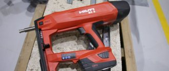
Twist welding machine of the TS-700 family
The device is a step-down transformer with adjustment on a thyristor control circuit, it allows you to weld any twists with a total cross-section of up to 25 mm 2.
The device can weld with pulsed, alternating or direct current, which allows you to connect not only copper conductors in the junction box, but other conductor materials, for example, aluminum, composite, steel. The device is very compact: dimensions 105x181x67 mm. Weight 5.5 kg. comes in a leather bag that slings over your shoulder. It’s easy to operate the equipment; you don’t need any welding skills; you can see how this happens in the video. Power supply is 220V household voltage, in welding mode consumption is 1.4 kW. The shielded metal housing protects household appliances from magnetic fields. The device is protected from possible overloads by a built-in thermal fuse.
Contents: 1. bag, the strap of which can be thrown over the shoulder; 2. safety glasses with “Chameleon” type lenses, which instantly react to the amount of light depending on the brightness of the lighting; when working, there is no need to constantly remove the glasses; 3. two power cables 1.4 m long for the holder and the electrode and the twist holder; 4. network cable 3 m; 5. Also included are 10 electrodes, which is enough for 10,000 welding times;
The estimated cost of the fully equipped device is only 7,300 rubles.
Sleeves
The third simple way to connect conductors is crimping with sleeves.
GML sleeves are most often used for joining copper wires. Deciphered as:
Sleeve
Copper
Tinned
For connecting pure aluminum - GA (aluminum sleeve):
To switch from copper to aluminum, special adapters GAM:
What is the crimping method? Everything is quite simple. Take two conductors and strip them to the required distance.
After this, on each side of the sleeve, the conductors are inserted inside, and the whole thing is crimped with press pliers.
Despite its obvious simplicity, there are several rules and nuances in this procedure, if not followed, you can easily ruin a seemingly reliable contact. Read about these mistakes and rules on how to avoid them in the articles “5 Rules of Crimping” and “Crimping Insulated Tips, Sleeves and Terminals”.
To work with conductors of large sections 35mm2-240mm2, a hydraulic press is used.
Up to cross-sections of 35mm2, you can also use a mechanical one with a large span of handles.
The sleeve must be crimped two to four times, depending on the cross-section of the wire and the length of the tube.
The most important thing in this work is to choose the correct sleeve size. For example, when connecting a monocore, the sleeve is usually taken to a smaller cross-sectional size.
For example, when connecting a monocore, the sleeve is usually taken to a smaller cross-sectional size.
And in this way you can connect several conductors at one point at the same time. In this case, only one sleeve will be used.
The main thing is to completely fill its internal space. If you are crimping three conductors at the same time, and you still have voids inside, then you need to “fill” this free space with additional pieces of the same wire, or with conductors of a smaller cross-section.
Only after this can you press.
After crimping, such a connection must be insulated. The most convenient way to do this is with a heat-shrinkable tube HERE.
There are tubes with an adhesive base. When heated, this glue flows out and ensures the tightness of the connection.
Insulation using a thermal tube is also a fairly simple process. In the absence of a gas burner or hair dryer, even a lighter is sufficient for small sections.
Sleeve crimping is one of the most versatile and reliable connections, especially when it is necessary to extend the cable, including the input cable.
In this case, the insulation turns out to be almost equivalent to the main one, when also using the outer tube HERE as a casing.
PPE
Let's start with the connection type PPE. It stands for:
- C connecting
- And insulating
- Clip _
It looks like a simple cap. Comes in different colors.
Moreover, each color means that it belongs to specific sections of the cores.
The cores are inserted into this cap and twisted together.
How to do it correctly, first twist the wires and then put on a cap or twist them directly with the PPE itself, is discussed in detail in the article “PPE cap for twisting wires.”
As a result, thanks to PPE, you get a good old twist, only immediately protected and insulated.
On top of that, it has a spring-loaded contact that prevents it from coming loose.
In addition, this process can be slightly automated by using an attachment for PPE for a screwdriver. This is also discussed in the above article.
How many wires should be in a twist?
Most often, it is recommended to collect no more than 6 cores with a cross section of 2.5 mm2. in one twist, or better, especially if you have little experience, no more than 4 times. Cables with this cross-section are used in apartments for socket groups.
You can take more conductors with a cross section of 1.5 mm2 used for lighting. And the cables going to the electric stove have a conductor cross-section of 6 mm sq. As you understand, even six pieces are very difficult to neatly twist together without experience.
In order not to memorize the maximum number of wires recommended for twisting:
There is a simple rule:
The total cross-section of all wires in a twist should not exceed 16 mm2, and the total number of wires is 6 pieces
Standard distribution boxes most often have up to 6 cable entry points, so twisting with a large number of conductors usually does not work.
Another simple explanation for the limitation of the maximum number of cores is the following: a larger number simply will not allow the tool to properly grasp them when working.
Therefore, I recommend not twisting more than 6 wires at the same time. But, with some skill and strong hands, or using various devices, in rare cases you can twist up to 8 pieces.
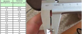
Below is a table that shows the recommended maximum number of wires in one twist for different cable sections:
| Wire cross-section mm.kv | Number of wires in twist | |
| Recommended | Maximum | |
| 1.5 | 6 | 8 |
| 2.5 | 4 | 6 |
| 4 | 3 | 4 |
| 6 | 2 | 2 |
| 10 | 2 | 2 |
When making electrical installations, try to avoid cases where it is necessary to twist more wires than are recommended here.
It is always better to make an additional junction box than to get a poor-quality connection, which will then cause you a lot of problems.
And once again I would like to remind you that officially, simple twisting in electrical applications is prohibited and is used only in combination with other connection methods - compression, welding, etc.
I am sure that there are a lot of people who will say that they can easily twist a larger number of wires with high quality, and the resulting connection is as reliable as possible. I won’t argue with this; moreover, in my practice I’ve had to do something like this (I always weld conductors after twisting).
A striking example of this could be an article about extending the input cable to an apartment, where 3 wires of 6 mm square were twisted. When using certain technologies, this is possible, but I do not recommend doing this all the time; use this opportunity only as an exception.
What do you think? Tell us about your experience in installing twists and the maximum number of wires that can be done efficiently. I am especially interested in the opinion of novice electricians who have decided to do wiring in an apartment or country house.
Is it possible to connect wires of different sections of the same material?
If, for example, you need to connect wires of different cross-sections (they are also suitable for the same cross-section) and the same material (copper or aluminum), then in this case the special connecting blocks presented below are well suited.
They have different numbers of inputs: in the figure, respectively: 2, 4, 6.
That is, this is a “sort of” twist for 2, 3, 4, 5 or 6 wires.
Moreover, if you need to connect 3 wires to each other, then for this you can use a block that has 4 or 6 inputs:
The block is simply pressed tightly onto the wires:
You need to understand that after connecting the wires in this way, they can no longer be removed from the block. Therefore, if you have never tried to work with such devices, buy a few of them in a store with a supply and practice at home. They cost pennies.
Methods for connecting wires or cables to each other
The junction of two conductors must meet the following requirements:
- reliability;
- mechanical strength.
These conditions can also be met when connecting conductors without soldering.
Crimping
This method requires special equipment. Crimping of wires with sleeves is carried out for both copper and aluminum wires of different diameters. Depending on the cross-section and material, the sleeve is selected.
Crimping algorithm:
- stripping of insulation;
- stripping wires to bare metal;
- the wires need to be twisted and inserted into the sleeve;
- the conductors are crimped using special pliers.
Selection of a sleeve causes major difficulties. An incorrectly selected diameter will not ensure reliable contact.
Bolted connection
Bolts, nuts and several washers are used for contact. The connection point turns out to be reliable, but the structure itself takes up a lot of space and is inconvenient to install.
The connection order is as follows:
- stripping of insulation;
- the stripped part is laid in the form of a loop with a diameter equal to the cross-section of the bolt;
- a washer is put on the bolt, then one of the conductors, another washer, a second conductor and a third washer;
- the structure is tightened with a nut.
Using a bolt, you can connect several wires. The nut is tightened not only by hand, but also by a wrench.
Terminal blocks
The terminal block is a contact plate in a polymer or carbolite housing. With their help, any user can connect wires. The connection occurs in several stages:
- stripping the insulation by 5-7 mm;
- removal of oxide film;
- installing conductors in sockets opposite each other;
- fixation with bolts.
Pros - you can connect cables of different diameters. Disadvantages - you can only connect 2 wires.
Types of terminal blocks for multi-core and single-core cables
There are 5 main types of terminal blocks:
- knife and pin;
- screw;
- clamping and self-clamping;
- cap-shaped;
- "walnut" type clamps.
The first type is rarely used; they are not designed for high currents and have an open design. Screw terminals provide reliable contact but are not suitable for connecting multi-core cables. Clamp terminal blocks are the most convenient devices to use; their installation does not require special equipment. Cap-type devices are also often used, but unlike clamping devices, caps can be used repeatedly. "Nut" is practically not used.
Terminals in junction box (copper or metal)
Terminals are the most common connection method in a junction box. They are cheap, easy to install, provide reliable contact fixation and can be used to connect copper and aluminum. Flaws:
- cheap devices are of low quality;
- Only 2 wires can be connected;
- Not suitable for stranded wires.
Self-clamping terminal blocks WAGO
There are 2 types of Vago terminal blocks used:
- With a flat spring mechanism - they are also called disposable, since reuse is impossible. Inside there is a plate with spring petals. When installing the conductor, the petal is pressed out and the wire is clamped.
- With lever mechanism. This is the best connector option. The stripped conductor is inserted into the terminal and the lever is clamped. Re-installation is possible.
With proper use, Vago terminal blocks last 25-30 years.
Using Tips
For connection, 2 types of tips and sleeves are used:
- in the first, the connection is made inside the product;
- in the second, two electrical wires are terminated with different tips.
The connection inside the sleeve or tip is strong and reliable. There are also special sleeves for connecting copper and aluminum wires.
Soldering of electrical wiring lugs
The tips are connected to the wiring using a press. If it is not there, contact can be ensured by soldering.
The electrical wire and the tip inside are tinned, the stripped cable is inserted inside.
The entire structure on the contact must be wrapped with fiberglass tape and heated with a burner until the tin melts.
Soldering
First, about soldering technology. The connected conductors are stripped of insulation, cleared of the oxide film to bare metal, twisted, and then tinned. To do this, the conductors are heated with a soldering iron and applied to rosin. It should cover the joint completely. Tinned wires are twisted first with your fingers, then pressed using pliers. Instead of tinning, you can use soldering flux. They wet the wires well, but after twisting.
Then, in fact, the soldering process begins: the joint is heated with a soldering iron or narrow torch. When rosin or flux begins to boil, take some of the solder onto the soldering iron tip and bring it into the soldering zone, pressing the tip against the conductors. The solder flows to fill the gaps between the wires, making a good connection. When using a torch, solder is simply added little by little into the torch.
Next, after the soldering area has cooled, according to the technology, it is necessary to wash off the remaining flux (they accelerate oxidation), dry the joint, cover it with a special protective varnish, and then insulate it with electrical tape and/or heat-shrinkable tubes.
Now about the advantages and disadvantages of this method of connecting wires. In low-current systems, soldering is one of the most reliable methods of connecting wires. But, when installing electrical wiring in a house or apartment, it is criticized mercilessly. The thing is that solder has a low melting point. When large currents periodically pass through the connection (this happens if the circuit breakers are incorrectly selected or faulty), the solder gradually melts and evaporates. Over and over again, the contact becomes worse and the connection heats up more and more. If this process is not detected, the matter may well end in a fire.
The second negative point is the low mechanical strength of soldering. It's the tin again - it's soft. If there are a lot of wires in a soldered joint, and if they are also rigid, when you try to pack them, the conductors often fall out of the solder joint - the elastic force is too great, which pulls them out. That is why it is not recommended to use soldering connections when wiring electricity: it is inconvenient, time-consuming and risky.
Important Notes on Wiring Connections
Let us note important points regarding electrical wires.
- All wires twisted together should not dangle somewhere in the air! They must be placed in a junction box.
- For all wire connections, ensure that the bare ends of the wires are completely hidden in the connection block. That is, try to make the connection so that after this connection it would be impossible to reach the bare end of the wire with your hand.
- Do not try to remove the wire from terminals that are not intended for this purpose. For example, there are craftsmen who manage to remove wires from wago terminals. But I do not recommend doing this, since such removal is always associated with deformation of the wire. And this is unacceptable, because the load on the network should be experienced by whole wires, and not half-broken ones, which can lead to short circuits.
This is where the article ends. We have studied in detail the issue of how to connect wires in an apartment. Now, when moving the socket from one place to another, you can easily extend the wires by laying them in the wall and making the correct connection.
They installed these pads for me at home... It would be better if they did everything with twists. The socket doesn't work and that's it. I called an electrician, he immediately said that the problem was in the pads and that they (the problems) would appear periodically. I reached into the box and sure enough: I turned the wire in the block, the socket started working. But problems cannot help but appear: in the block the wires are pressed with thin petals, very similar to steel ones. So I'll look for something else instead of pads...
I’ll honestly tell you that I made all the connections at home through the blocks. The kitchen has a lot of electricity supply: 3 sockets, heated floor. dishwasher, hood, microwave and everything is on blocks that are hidden in junction boxes or sockets.
I don’t argue that there are cases, but these are the exception rather than the rule. There might have been a defective batch. And the examples are very different. Some people's walls fall apart after plastering, while others have had no problems for 25 years. But this does not mean that now there is no need to plaster the walls. Somewhere the technology was broken. Therefore, here we need to study the problem, look deeper into why this is happening. And if twists were the most reliable, then firefighters would not prohibit them.
Hello. I am installing electrical wiring for a mini-bakery. Everything is great except for one thing. The fact is that I am opening a company in a remote corner from civilization in a small village. The city is 2000 km away and only by plane. Therefore, I stocked up on everything in advance. Except of course the wires. And then I somehow found the usual white two-wire and three-core aluminum noodles with a cross-section of 1.5 sq. mm. and copper three-core 2.5 sq. mm. Three-phase electrics. I installed 2-wire noodles for lighting, and three-wire for sockets with chargers. I have only three equipment supplying 380 W. Dough mixer 2.4 kW, Flour sifter 1.2 kW, Oven 19.2 kW. Since there is no choice, all three of them carried out wiring with a cross-section of 2.5 sq. mm. In addition to the stove, the dough mixer and flour sifter work perfectly. But when I turn on the stove after 5 minutes, the RCD 63A 30Ma turns off the electrical supply. I think this is due to the cross-section of the wire because... I found on the instructions that you need to use a wire with a cross-section of 6 sq. mm. How can you get out of the situation? Of course it would be great to find a 6 sq. mm wire. But I only have 2.5 sq mm. Please tell me whether it is possible to use a three-core wire as one wire, i.e. connect all three to one?
Yes. It would be optimal to make all three wires of one wire 1 phase (7.5 sq. mm), another 3-core wire for the second phase, and also for the third phase, also for zero (also 7.5 sq. mm, respectively), and grounding. With such loads (about 60 A), no terminals will withstand (except screw ones. But for myself I wouldn’t risk it), it is necessary to twist, which should be tinned and soldered (use acid-free flux, solder and a simple gas torch + futor (copper tube with a diameter of 25mm, one end is rolled onto a holder so that the solder does not leak out, approximately 3cm deep), or a welding machine and a copper electrode (boil the ends of the twists until all the cores are welded together into a ball at the end).
Welding – high reliability in any conditions
When connecting wires by welding, the conductors are twisted and their ends are welded. As a result, a metal ball is formed, which provides a stable and very reliable connection in any conditions. Moreover, it is reliable not only in terms of electrical characteristics, but also mechanically - the metal of the connected wires after melting forms a monolith and it is impossible to isolate a separate conductor.
Welding - it is important to heat the metal, but not melt the insulation
The disadvantage of this type of wire connection is that the connection is 100% permanent. If you need to change something, you need to cut off the fused piece and do it all over again. Therefore, for such connections, a certain supply of wires is left in case of possible alterations.
Other disadvantages include the need for a welding machine, appropriate electrodes, flux and operating skills. In addition, welding takes a lot of time, it is necessary to protect surrounding objects, and it is also inconvenient to work with a welder at height. Therefore, electricians practice this type of connection in exceptional cases. If you are doing it “for yourself” and know how to handle a welding machine well, you can practice on scraps. The main trick is to not melt the insulation, but to weld the metal.
After cooling, the welding site is isolated. You can use electrical tape, you can use heat shrink tubing.
Methods of connecting wires: procedure for performing the operation
Twisting is considered the most common option for fastening several conductors together. For this method, it is enough to remove the insulation from the current-carrying wires and twist them tightly together.
Important! For maximum reliability of such a connection, it is recommended to remove the insulation material by at least 5 cm. For good contact, the wires are pressed with pliers
The method of soldering two conductors takes a little longer than the previous one, but it is more reliable. The ends of the conductors are coated with tin or rosin, and then carefully soldered. Such fastening does not create much resistance in the conductors.
The welding method is similar to soldering, but requires more care and the involvement of specialists for such work.
Connection terminals are the most popular and advanced option. Similar fasteners are used in switchboard devices and distribution boxes. The convenience of the connection lies in the ability to use current-carrying conductors of various cross-sections and materials of manufacture.
Spring fasteners are not inferior to pads. The method of such a connection is no less reliable, but efficient. With this, everyone can cope with the task of connecting electrical wiring. In home improvement, the use of bolted clamps and connections is practiced. The only drawback of such fasteners is the mandatory and durable insulation. These devices are used to fasten stranded wires and conductors with different cross-sections.
Spring terminal blocks for wires of different sections
Connecting blocks - latches
There are also jumper blocks that will allow you to connect wires together, but if you make a mistake, you can disconnect any of the connected wires. These are the so-called latches:
For latches, you should definitely check with the seller in the store about the possibility of connecting wires of different materials and cross-sections.
Connection between 6 wires
YOU'RE LYING!!!
In fact, INSULTING the members of the forum who have repeatedly and extensively discussed the types of contact connections, for example, RESEARCH Kamikaze, who described the different types of contact connections in the MOST DETAILS of anyone on the Russian-speaking Internet!
This is not to mention VIOLATION of the forum rules which state that before creating a topic you need to read the forum to see if there is a discussion of something that interests you.
Welding, soldering, IDEALLY a combination of them, in extreme cases crimping, if in combination with soldering then also IDEAL, for example, in high-current circuits I solder the NShV(I) tips after crimping from the end, since the classic termination of NShV(I) in high-current circuits is not refers to the best solutions, in the worst case scenario, clamping with two screws at the same time!
To be on the safe side, you can use 4 screws at the same time.
In the link below, in my next message in that topic, a photo where 7 cores of 2.5 mm2 are connected by soldering, I immediately took “on my knees” after reading the message that it is not clear how to connect 7 cores of 2.5 mm2 by soldering, to show that if hands artisans, there is nothing complicated.
Yes:
Flat spring terminals, so-called screwless, self-clamping, produced by WAGO, Weidmuller, Legrand, ABB, Schneider, Hager and other manufacturers, either according to the standards for contact connections, or by common sense, or by the instinct of self-preservation, CANNOT be used in distribution, installation boxes, shields, sockets, about which I have been warning everyone in more detail for a long time on the vastness of the Russian-speaking Internet, for example on this forum in the topic!
In the topic he added that self-clamping, without screw, flat spring terminals CANNOT be installed even on lighting groups with a 1A automatic machine, since they will not withstand the pulse current that the core will withstand! That is, the conductors connected through such a terminal are essentially connected through a FUSED link! Which was subsequently confirmed by the case described on a similar forum in the topic!
Flat spring terminals, the so-called screwless, self-clamping ones, are recommended to be used in stationary wiring only by those who do not understand electrical/fire safety or by INTENTIONAL hacks, since it is many times, and sometimes even orders of magnitude, more convenient and faster to install contact connections!
SELF-CLAMPING, SCREW-LESS, FLAT SPRING TERMINALS ARE WORSE THAN Twisted!!!
Plastic junction box, plastic corrugated wiring behind a suspended, suspended ceiling, in cavities, money down the drain and DECORATION in the fire resistance of the room!
It is optimal to make RELIABLE contact connections behind a suspended, stretch ceiling, in cavities without boxes and to insulate them WELL!
If you make distribution boxes behind a suspended, suspended ceiling, or in cavities, then use steel!
Also, behind a suspended ceiling, especially a suspended ceiling, in cavities, plastic wiring fasteners are not among the best solutions!
MORE RELIABLE and cheaper than plastic wiring fasteners, the remaining cores, flexibility class 1, from the wiring!
Where aesthetics are visible and required, steel reinforcement!
You need to try, from the same cable manufacturer, the sleeves often have different dimensions.
If you spend money on a tool, then on soldering irons, it’s cheaper and there’s a higher chance that it will be useful later in everyday life.
Possible problems with such a connection
We list the main problems of connecting two wires to one machine :
1) Overstating the machine - the wiring will burn out
Each machine has its own nominal characteristics. Each wire also has its own characteristics, depending on the cross-section of the wire and its type. In electrical applications, copper wires are the most popular.
In the case when the wire cross-section is designed, for example, for a current of 21 amperes (for a wire with a cross-section of 1.5 mm2), the machine must be installed with a rating of no more than 16 amperes. Considering that with an overload of 45%, any circuit breaker may not turn off for 1 hour (1.45 * 16 = 23.2 A), the wire will have a certain safety margin.
The main purpose of the machine is to protect electrical wiring and electrical appliances connected to it from high currents that occur during a short circuit and overload.
It happens that a circuit breaker is often knocked out, while many simply replace it with a circuit breaker of a higher rating. But at the same time, the installed machine accordingly passes a current whose strength exceeds the maximum possible for normal operation of the wiring. As a result, such wiring burns out, melts, and can even short out due to insulation failure.
When connecting two wires to one machine, follow a very simple rule:
| Both wires must be of the same cross-section and correspond to the rating of the machine! |
For example, a 16 amp machine is available. For proper connection, we take two NYM type cables with a cross section of 3×2.5. The maximum permissible continuous current value for such a cable is 25 A if the cable is hanging in the air, and 38 A if it lies in the ground. Since our cable does not lie in the ground, so as not to test it under maximum loads, a 16 Ampere circuit breaker is the ideal solution for such a cable, and in our case, for two wires.
2) Poor contact at the terminal
When connecting two wires to one machine, a problem arises: how to ensure tight contact between the machine terminal and both ends of the wire.
It has already been written above that the wires must be of the same cross-section. Why? When connecting wires of different cross-sections to the circuit breaker, when you tighten the terminal, one of the wires will not have good, tight contact with the terminal due to the larger wire .
Many “Kulibins” will immediately say “twist two wires of different sections into a twist and you will be happy.” There are statistics for this that show that twisting is the most common cause of malfunction in electrical wiring. Due to poor fastening, the twist will constantly fall out, or, no, touching the terminal of the machine, it will short out.
Two wires of the same cross-section will fit perfectly into the terminal of the machine without twisting. If you need to connect wires of different sections or more than two in number, then it is better to use special cross modules or buses for these purposes.
To connect multi-core wires, there is a decent way out of this situation - NSHVI lugs (insulated pin sleeve lug). These are special connectors that are designed to connect two wires. They have a cone-shaped input and a metal contact that is directly inserted into the terminal of the machine.
NShVI tips are divided into two types: NShVI and NShVI-2. NShVI are designed for terminating the cores of one wire, and NShVI-2 is for terminating two multi-core wires with one sleeve with the possibility of connecting them later to one terminal.
The use of such tips will ensure, firstly, ideal contact of the electrical wiring with the terminal of the machine, and secondly, it will give an aesthetic appearance to your panel. All connections will be neat and reliable without any twists, and two wires will be connected perfectly into one circuit breaker.
Connecting mono-core and multi-core in the terminal of the machine
Friends, especially for comment No. 1 under this article, I decided to consider another way to connect two wires in a machine, and the wires are different in design. We are talking about connecting single-core (monolithic) and stranded wires to the terminal of the circuit breaker.
The NShVI tip will help us with this. We take two wires, remove the insulation from them and crimp them with a double tip. In my example, both monolithic and stranded wires with a cross-section of 2.5 mm2 are crimped NShVI(2)-2.5.
The advantage of this connection is that the wall of the tip itself is thin and under the action of the screw force the sleeve will compress, thereby improving the connection of the wires.
PS There is no need to twist the wires when crimping. Moreover, you don’t need to just stick such a twist under the terminal. When tightening, half of the strands will simply be damaged, and this will lead to poor contact and GOOD heating in the future.
| In general, it is best in such cases to buy another circuit breaker, add it to the panel and connect each cable to its own circuit breaker. It will be BETTER and MORE RELIABLE. But if suddenly..., suddenly... this is not possible, then we use the methods indicated in this article. |
3) The connected load exceeds the power of the machine
It happens that several devices are hung on one machine, the power consumption of which exceeds its rated current, which is why the latter constantly knocks out immediately when the electrical devices are turned on at the same time.
I’ll tell you a situation in which I myself was directly involved. One day I was invited to repair the wiring (at least that’s how they phrased the request over the phone). In the end I came across the following:
- 1. Small gym with two boilers
- 2. 16 amp machine
- 3. Each boiler has a separate cable line with a separate socket
- 4. Both wires are connected to the same terminal of the circuit breaker.
When both boilers were turned on at the same time, the machine immediately went off. Now we look at the power of each boiler. It turned out to be the same: 3.5 kW for each. The cable type for each boiler is a three-core cable VVG-nG-Ls, cross-section - 2.5 mm². Now we count:
- — Current load for one boiler: 3.5 kW × 1000 = 3500/220 volts = 15.9 Amperes.
- — Both machines consume a total of 31.8 Amperes.
As you can see, the load on both boilers exceeded the rating of the 16 Amp circuit breaker twice. In this case, the cable used allows a load of up to 27 A. Accordingly, the wire to the boiler is normal, we leave it. Now we remove the 16 A circuit breaker and install two 20 A circuit breakers.
We connect each boiler to a separate machine. It would be possible to take two 16 A machines, but then the rating of the machine would be one tenth higher than the boiler load (16-15.9=0.1). In this case, constant operation of the thermal protection is POSSIBLE.
Since our cable allows you to connect a 20-amp machine, we can safely connect both machines to 20 A and connect a boiler to each separately. That's it, the problem is solved.
Important! Before installing a machine with a higher rating , be sure to check that the rated current of the cable matches it. If the rating of the machine is much greater than the maximum load on the cable, then the cable may be damaged during the next overload, and the machine will not even react to this overload.
Important! When connecting boilers, it is recommended to immediately install an RCD (residual current device). If you have an RCD, you won't get an electric shock even if you stick your fingers into the socket (but don't experiment under any circumstances!). This device instantly triggers when there is a current leak, so a person does not have time to feel a noticeable electric shock.
Useful tips from professionals
Twisting of wires as such is prohibited by the PUE, but if it is used in conjunction with other means, it does not contradict anything:
- Welding. If you simply attach two wires to each other and weld them, you will get a good permanent contact. And if the cores are also twisted before this, the contact area will increase significantly, see the photo below.
- Soldering. The situation is the same as with twisting, only in soldering there is a main problem - solders, for example the widely used POS-60, do not provide mechanical strength. So if you solder two complex wires side by side and insulate them and hide them in a junction box, then such a connection will of course work. But if the wire moves even a little during operation, the soldering will break. Therefore, always twist the wires if you choose soldering as a method of connecting wires.
- Use PPE caps. To do this, you need to fold the connected wires together, insert them into the cap and begin to twist the cap clockwise. The spring in it will clamp the veins and they will twist.
- Clamp the twisted wires with a screw terminal block (they are also called polyethylene terminal blocks).
It is important to note that none of the above options makes the twist waterproof, so if you decide to fasten the conductors under the plaster in the wall, without a box, be sure to insulate the connector with cambrics. That's all you need to know about how to properly twist wires with your own hands.
We strongly recommend that you use more modern methods, and use twisting only when installing temporary electrical wiring! Do not twist under tension under any circumstances, because Today there is no such safe method. Any electrical installation work must be done with the lights turned off!
That's all you need to know about how to properly twist wires with your own hands. We strongly recommend that you use more modern methods, and use twisting only when installing temporary electrical wiring! Do not twist under tension under any circumstances, because Today there is no such safe method. Any electrical installation work must be done with the lights turned off!
Junction box and what it is
All wires that supply electricity to a house or apartment come out of the electrical panel. Each room has several sockets and switches. To collect all the wires in one place and assemble a wiring diagram, junction boxes were invented. This is where they are connected for the further operation of all devices. For laying the wiring, established rules are used, described by the PUE, which stipulate the rules for laying wires and cables. It also contains recommendations regarding the conduct of connections and branches of wires, specifically in the junction box. According to these recommendations, the wires are laid along the top of the wall, at a distance of 15 cm from the ceiling surface. As soon as the wire reaches the turning point, it is lowered perpendicularly down, and the specialist installs a box at the branch point. According to this principle, all wiring cores are connected according to a given diagram. Depending on the type of installation, the boxes are:
- internal, used for hidden wiring;
- external, used for external connection.
When installing an internal box, you need to make a hole in the wall, into which the box is then installed. When the cable is supplied and connected, the box is closed and the lid is flush with the wall surface. In some cases, such a box is masked with wallpaper or a thin layer of plaster. If the thickness of the walls does not allow installing an internal box, then the only solution is to install an external type box. It is mounted on the wall surface, so complex preparatory work is not required. Depending on the shape, the box can be:
- round;
- rectangular.
The number of pins varies, in most cases there are 4, but sometimes there are more. Each terminal is equipped with a thread or fitting to which it will be convenient to attach a corrugated hose. The corrugated hose is designed for convenient location of electrical wires, so replacing a damaged cable will not cause difficulties even for a beginner:
- disconnect the corrugated hose from the junction box;
- disconnect from the socket or switch;
- pull a little;
- pull out;
- put another in its place.
If the cable was laid in a groove, then replacing it will be more difficult. You will need to dig into the wall and remove the damaged cable, and lay a new one in its place. After such work, the wall will have to be repaired. The task of distribution boxes:
- Increase the maintainability of the power supply system. The accessibility of all connections allows you to identify the damaged section of the circuit. If all the wires were laid in corrugated hoses or pipes, then replacing damaged ones will not cause much difficulty.
- Providing free access to connection points. Since the majority of electrical problems arise from poor-quality or incorrect connections, you can easily check their condition by opening the junction box.
- Ensuring fire safety.
- Financial savings. By using a distribution box, you don't have to run a cable to each outlet.
How to connect 3 wires
Quite often a situation arises when it is necessary to connect not two, but three wires, for example, when supplying energy from one phase to two consumers at once, and in such cases, the most convenient method of connection is a mechanical clamp.
Depending on how large the load will be, it is necessary to select the appropriate model of the clamp used. The simplest option is a metal sleeve into which wires are inserted on both sides, on the one hand supplying, and on the other, pre-twisted together, feeding.
If one of the wires has a larger cross-section, then it is this wire that is inserted into the sleeve without twisting. After the wires are inserted, the connection is secured with clamping screws.
If the wires are of small cross-section, then the usual twisting of all three is used; pliers are used to ensure a tight connection. The twisting area can be covered with a plastic threaded cap.
Preparing to connect wires
Any electrical installation work should be carried out competently. It is important to remember that the safety and life of all people and animals living in a house, apartment or country house depends on the correctness of their implementation. A mistake is unacceptable - at best there will be no good contact. And these are non-working electrical points.
In the worst case scenario, a visiting family member, friend or acquaintance could be electrocuted by an improperly insulated connection. Or the wiring will catch fire, which could lead to a fire.
For high-quality and correct execution of electrical wire connections, you need:
- knowledge of the basic types and principles of connections;
- availability of special tools for electrical installation work;
- availability of all consumables that will be useful when performing a specific type of connection;
- preliminary training on individual sections of wires.
When everything you need is available, you should carefully prepare your future place of work. To do this, you need to de-energize all the wires that you have to deal with. This is a very important step that cannot be ignored!
To avoid getting an electric shock, it is better to make sure once again that the apartment or house is actually de-energized. In this case, it is convenient to use an indicator screwdriver - this is an inexpensive tool that can even be purchased in an online store.
In a situation where there are serious concerns about the advisability of carrying out electrical installation work yourself, it is better to contact an electrician. Moreover, you should invite only an experienced craftsman who has not only experience in carrying out such work, but also special education.
Electrician services will be especially relevant if the wiring in the entire apartment/house needs to be replaced. You can’t save on this - you can end up paying double or triple the price, or even pay with your property.
Let's take a closer look at the types of clamps
There are different types of terminal blocks designed to perform specific jobs. We will now try to consider the most common products.
Screw terminal block
The screw connection remains familiar and popular. The mechanism of the product is quite simple and reliable. Screw terminal blocks can be found on household wiring connections, inside many electrical appliances, and even car battery terminal clamps also belong to this group. But, if the electrical terminal blocks for electrical wiring have a copper or brass jumper inside, then the battery terminals are most often made of lead. This is due to the fact that there is acid inside the battery.
The advantage of screw terminal block models for connection is the high-quality contact of the entire area of the cable core with the metal jumper of the clamp. The screw allows you to easily connect and disconnect the wire. On many screw models you can find a screw marked green. It is used to connect the grounding conductor. The special feature of the clamp is its teeth. When pressed hard with a screw, they cut into the metal, improving grip.
The disadvantage of a screw clamp is that it can only be used with copper wire. You can, of course, clamp an aluminum core, but if you don’t calculate the force, the brittle metal will deform. Another disadvantage is the inconvenience of use. In order to connect many wires with screws, it will take more time than to perform a similar operation with spring mechanisms. When in a hurry, inexperienced craftsmen often completely unscrew the clamping screw and lose it. However, these minor problems do not deteriorate the quality of the screw connection, but the fact that the screw connection can become loose during vibration determines its main disadvantage.
Crimp terminal block
This type of electrical product is intended for connecting cable cores with a maximum permissible current of 24 A. The terminal block attached to the cable can withstand up to 5 thousand volts. With one product you can immediately crimp up to 8 prepared terminals for connection. This design greatly simplifies the installation of electrical wiring. According to the type of fixation, the terminal block can automatically fix the contact inside the socket or mechanically, which is done manually. If you correctly calculate the force when crimping the terminal block, you will get reliable contact.
Product labeled PPE
Such terminal blocks are called insulating and look like a plastic cap. The clip is made of heat-resistant polymer that is flame resistant. There is an opinion that PPE is intended to protect the connection from fire. In fact, the terminal block creates a strong mechanical contact and will withstand voltages up to 600 volts.
The principle of operation is simple. There is a usual twist of exposed wire strands. Moreover, all wires must be made of homogeneous metal. To avoid oxidation, it is advisable to treat the twist with paste. There is a cone-shaped spring inside the plastic cap. This will create a strong connection. The cap is put on the twist, twisting clockwise. At this time, the spring presses the veins in turns, creating a strong contact. If two wires of equal thickness are connected, they do not need to be twisted. The bare ends are forcefully inserted into the cap and rotated. The spring inside will do its job itself.
Power terminal blocks on DIN rail
Power terminal blocks are installed on a circuit board or DIN rail. Their complex design allows you to connect wires of different thicknesses up to 300 mm 2. connect aluminum wire with copper, and also simultaneously connect cable cores designed for different power. The power terminal blocks have a tinned copper plate, to which the wire is pressed with a special conical washer, which does not allow the connection to loosen.
Universal and Barrier Clamps
These products have a special design feature - a metal plate. It is divided by cells of insulating material. The cell jumpers prevent the wires being connected from touching. Reliable fastening of the cores is ensured by screws. On metal terminals, aluminum wire practically does not oxidize, which allows the use of such terminal blocks without restrictions. Most often, the connections of wires in the distribution box are made using barrier clamps.
Tags: machine, beat, sconce, view, choice, house, , clamp, grounding, isolate, insulation, pulse, cable, how, design, , installation, power, load, voltage, crimping, lighting, rule, wire, start , , work, size, socket, row, garden, light, twist, connection, ten, type, current, , installation, phase, photo, shield
Wago Clamps
This type of connection has conquered the market with its convenience and ease of use. They connect all kinds of conductors. Clamps are available for different numbers of connections.
The disadvantage is that the design contains a spring, which can weaken over time, which can lead to an accident and fire. Therefore, you should purchase only original, branded products.
vote
Article rating
Where is electric twisting used?
Twisting of wires is performed to connect them electrically and mechanically. This connection method does not imply the transmission of high power. Therefore, they try to use twists only in low-current circuits and rooms without high humidity.
Connecting cables using twisting
Reliable twisting has the following properties:
- Low contact resistance. Otherwise the contact will burn out.
- High mechanical strength. Especially for wires suspended in the air.
- Tightness of the connection. When exposed to water, the twist oxidizes and burns.
- Conformity of metals of current-carrying conductors. Contact between copper and aluminum wires is not allowed.
Important! When installing electrical wiring in an apartment, the twists should be placed in junction boxes. This measure will protect the contact from dust and moisture and make it more accessible for maintenance.
Why is twisting dangerous?
The main danger is high resistance. In addition, if the connection is poorly tightened or gets hot, then this indicator becomes even worse.
The twisting point acts as a low-resistance resistor. Under the influence of current, thermal energy is released on it. It promotes oxidation of the twist and further deterioration of the contact. As a result, the wires connected in this way simply burn out. Often this is what causes device breakdowns and wiring short circuits.
Burnt twist
We twist it ourselves
During professional installation, special clamps are used to make the connection - PPE (connecting insulating clamp); when using them, the final twisting is allowed from the point of view of the PUE, but it is worth remembering that such a device is not designed for high currents.
So, how to properly twist wires at home? To carry out this manipulation you need:
- take into account all the nuances in advance (location, load of connected equipment, etc.);
- acquire the necessary tools (pliers, knife, sandpaper, heat shrink, it is advisable to have a hot air gun and a device for removing insulation, a screwdriver if available).
Let's consider the situation with weaving from a cord with a monolithic core:
It is necessary to strip the ends of each wire by 3–4 cm using a special tool (stripper) or a construction knife
It is extremely important to remove the insulation and not leave deep cuts on the core. Then we put heat shrink on one of the ends. Then degrease the cleaned surfaces with alcohol/acetone/white spirit. Then, taking sandpaper, we clean the wire strands. We lay the wires parallel to each other and hold them with pliers. We weave (in accordance with the diagram) clockwise, at least 5 turns for one core. The wires must fit tightly to each other. We move the heat shrink to the contact point and warm it up with a hairdryer or lighter
It is important that the heat shrink fits tightly at the twisting site.
With a stranded cord the situation is a little different:
We strip the ends of each wire by 3–4 cm using a special tool (stripper) or a construction knife
It is extremely important to carefully remove the insulation and not damage/cut off the cord cores. We put heat shrink on one end of the cord. We unravel the strands of each cord into small “braids”. We degrease the resulting “braids” with alcohol/acetone and so on. We lay the cores on top of each other from each cord. We weave together, making the connection tight (at least 5-6 turns per braid). We move the heat shrink to the place of twisting, warm it up with a hairdryer/lighter. The heat shrink should fit tightly at the joint.
If it is necessary to create a “braid” from monocore and multicore cords, the algorithm also changes, and it is highly advisable to weave using the “Branching” method:
- We strip the ends of each wire by 3–4 cm using a special tool (stripper) or a construction knife. We take care not to damage the cores of each cord.
- We put heat shrink on one of the cords.
- We degrease the cleaned areas with alcohol/acetone and so on.
- We bend the single-core end 180 degrees, so that it then presses the twist.
- We twist the multi-core cord around the single-core end in accordance with the diagram (clockwise), at least 5-6 turns, the more the better.
- We clamp the pre-bent end of the single-core wire and press it against the twist made with pliers.
- We move the heat shrink to the contact area and heat it with a hairdryer/lighter. We make sure that the heat shrink is well fixed at the twisting site.
At this point, we can consider the work done competently and efficiently. If you follow the instructions and take all necessary measures, you are guaranteed to get a high-quality connection for a long time.
Blog
Twisting wires is prohibited by the pros!
Not long ago, at one site in Minsk, I saw electricians who were twisting wires and smearing them into the walls. To my remark, they made excuses that they do everything that way. It turned out that the guys came from the region, and for them this method of connection is common practice - cheap and fast. For such “masters” I would like to remind you that twisting wires and leaving them like that is IMPOSSIBLE!
According to technical standards in the Republic of Belarus, ordinary twisting in electrical wiring is prohibited:
Indeed, the PUE does not allow the use of twisting to connect wires. However, copper twisting, if done by a professional craftsman, can easily support a load of 16 A, without any negative consequences. If the load is greater, the contact will deteriorate and burn out over time.
Important
There is another interesting paradox here: despite the fact that twisting is heavily criticized, all the burned twists that I have seen were not done professionally. Most of them were aluminum. Aluminum is generally a very capricious conductor; it behaves poorly in any connection and requires special attention. But even such twists can cope with household loads in apartments.
However, despite this, twists are evil. Why?
Firstly, they have a high transition resistance and secondly, they are very sensitive to pulse currents. In addition, not everyone knows how to do twists correctly.
What should the twist be? The correct twist should be 3-5 cm long (depending on the cross-section and number of strands - the thicker and larger, the longer), twisted tightly but “without wings”.
Typical mistakes when twisting:
In the photo, I tried to imitate the incorrect wire connections that I encountered in apartment wiring:
- Option a) – insufficient twist length.
- Options b) and e) are not twists at all, but they are one of the most favorite connections of homemade “crazy people”.
- Options c) and d) – untwisted and poorly twisted twists.
Another of the most common types of connections is twisting an aluminum core with a copper one:
and connection of a mono core and a stranded wire:
All this is an example of bad connections. It is IMPOSSIBLE to use such connections in electrical wiring!
Where can you use WIRES TWISTING?
I use regular wire twisting only as a temporary connection or as a preparatory operation for other types of connections (for example, for welding or soldering).
Summary: Twisting is bad! Use reliable types of connections: welding, crimping, 3M clamps.
Types of twists
There are dozens of twist options. They differ in the structure of current-carrying conductors, material and complexity of manufacture. If we consider from the point of view of purpose, twists are divided into 2 categories:
- Branch. The 1st wire remains intact. Only a piece of insulation is removed from it. Another wire is wound onto the bare current-carrying wire.
- Extension. Used to connect the free ends of 2 wires of the same cross-section. Cables are lengthened in this way.
Stranded wire branch
Pros and cons of using twists
Despite the risk of fire, twisting is very often used by electricians. This is explained by the advantages that this type of connection has:
- this is the cheapest way to connect wires;
- All you need is a knife and insulating tape;
- ease of manufacture;
- takes up minimal space.
Twisting is the easiest way to connect wires.
There are also disadvantages:
- such a connection is prohibited by the rules of the PUE;
- risk of fire;
- Twisted wires are difficult to separate.