Quite often, welders have problems connecting cables . This question may arise for several reasons: the wire that comes with the welding machine is not long enough, or the cord was broken or damaged during work. Therefore, it is important for performers to know how to properly connect welding cables and extend them.
Device
Of the available metals, copper serves as the best conductor .
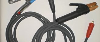
Combined with its flexibility, this makes it an ideal material for making the base of welding wire - conductors. The structure consists of the following main parts:
- copper core, twisted from a large number of copper wires with a diameter of up to 0.5 mm;
- separating layer - a thin shell that prevents the core and the insulation layer from sticking together, can be supplemented with talc or other powder;
- an insulating coating consisting of rubber, rubber or other polymer.
The ends are provided with contacts to connect to the inverter and holder. They are crimped and soldered to ensure the best contact.
Characteristics
The most important characteristic required for a wire is its cross-section . It determines the maximum current passing through the cable. No less important is the resistance, which causes electricity losses on the way from the device to the electrode. Mechanical parameters are of great importance:
- strength: ability to withstand loads;
- elasticity: the ability to return to its original shape after deformation
- temperature resistance: the ability to maintain working properties when temperature changes;
- ability to withstand sunlight and humidity;
- resistance to fungus and mold;
The set of connecting welding wires supplied with the device corresponds to its permissible cross-section and length.
Kinds
With household and semi-professional class inverters, the most common in home workshops, single-core wires of the KG brand are mainly used.
Depending on their purpose and characteristics, they are:
- KG-HL , insulation is made of frost-resistant rubber, they work in the cold;
- KG-T , insulation impregnated with substances that prevent the growth of fungus and mold, used in humid climates
- KOG , highly flexible wires, for welding in hard-to-reach places, for example, in shipbuilding.
According to the number of cores they are divided into:
Single-core
Most of the inverter wires are single-core.
One wire connects the device terminals to the electrode holder, the other to the ground clamp on the workpiece.
Twin-core
Used for high frequency welding and alternating current operation . Two cores have their own insulation; the outside is covered with another insulating layer. Alloys of copper and other non-ferrous metals are used as materials.
Three-core
Such wires are used to connect automatic welding systems connecting pipelines and large containers.
Each core also has its own insulation.
Methods of working with different metals
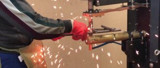
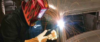
Since the welding process is impossible without igniting the arc, you should know that there are 2 methods to do this:
- you need to hit the metal with the electrode several times until the arc ignites.
- You need to strike the metal with an electrode, like a match, several times.
Each master selects the most convenient and suitable method of igniting the arc. But you need to scratch not just anywhere, but along the line of the weld, so that no marks are left on the workpiece.
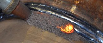
The place where metal melts under the influence of an electric arc is called a weld pool. To move it along the seam line, use one of the methods shown in the following figure.
For normal movement of the bath, the electrode is tilted at an angle of 45-50°. By tilting the additive at different angles, you can control the width of the bath. Each master selects the optimal angle of inclination to obtain a seam of acceptable quality.
The electrode can be positioned at a backward or forward angle. To obtain a wide seam, the equipment is tilted at an angle forward, since this method produces less heat. Thin metals are welded using this method. It is customary to weld thick metal at an angle backwards.
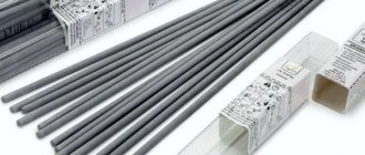
To weld non-ferrous metals, you will have to connect an argon torch to a welding inverter and use a non-consumable electrode (tungsten). The additive in this case is metal rods, which are placed on the weld line and melted by an electric arc. During the welding process, the pool is blown with inert gas.
Section selection
The correctly selected welding cable cross-section for the inverter will allow you to work safely and with the expected performance. If the wire cross-section is insufficient, the resistance of the wire will cause loss of current due to its heating; as a result, the machine will not be able to develop the required welding current and the quality of the seam will deteriorate sharply. In this case, the indicator on the inverter will blink , indicating an overload.
Important! If you operate an overheated cable for a long time, the insulation and connection terminal may melt. This often leads to equipment failure and even fire.
In order to connect low-power portable inverters operating from a 220V network, light and flexible wires with a cross-section of up to 16 mm2 are used.
For more productive devices, a cross-section of up to 50 mm2 will be required.
How to hold it in a holder
The method of fixing the welding cable depends on the type of electrode holder : homemade or purchased (produced by companies of the corresponding profile).
Types of homemade holders and methods of assembling them, their main advantages and disadvantages are discussed in the article “Electrode holder for a welding machine.” This article also presents a method for correctly and securely connecting the cable to the electrode holder.
You should also pay attention to the recommendations of the master , who will help you make a professional, competent holder yourself. For clarity, a video of the assembly of the holder is presented.
To understand how to connect welding cables to the purchased holder , we recommend that you watch the video below. The performer can clearly see that the cable, together with a metal gasket (plate), is inserted into the corresponding hole and securely fixed with a key by tightening the screws.
Correct connection
Proper connection ensures the welder productive and safe work.
Connecting wires to a welding machine requires compliance with a number of rules:
- there must be a terminal at the end, crimped or soldered;
- The wire cross-section must correspond to the maximum operating current of the device plus a margin of 20%
- You should carefully monitor the polarity of the connection and observe it;
- The cable must lie freely in the work area, without tension or loops.
How to connect a welding machine if there is not enough wire to the welding zone? You can increase its length.
Industrial products
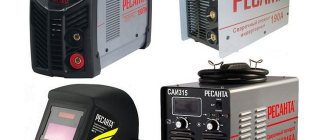
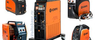
Industrial designs of generators used to supply power to mobile welded equipment can have a wide variety of designs. From the point of view of economy and efficiency, the option of a gasoline unit of the same inverter type is considered optimal. In this case, preference is usually given to devices from the same manufacturers, designed specifically for working with inverter welding equipment (figure below in the text).
It is believed that it is this combination of these two components of the working complex that makes it possible to obtain a sufficiently stable arc and provide the required parameters of high-frequency voltage and pulse current. According to their class and intended purpose, all existing welding devices are divided into the following types:
- Purely industrial designs;
- Professional models;
- Inexpensive household products.
Industrial and professional models are mainly used for the manufacture of volumetric metal structures and are designed for round-the-clock operation for long periods of time. For their normal functioning, significant operating currents will be required, capable of ensuring high-quality assembly of industrial structures. This type of welding device will require gasoline generators capable of delivering currents of up to 250-500 Amperes (see photo below).
Summarizing the consideration of possible options for choosing a generating device for an inverter, it is necessary to note the following. When thinking about the question of which generator is best to choose for welding, most users give preference to small-sized gasoline units in inverter design.
Is it possible to extend the welding cable on the inverter?
When increasing the length, you need to understand that the longer the cable for connecting the welding inverter, the greater the losses and the lower the resulting current strength.
If it is necessary to weld at a great distance from the machine, wires of a larger cross-section should be connected to compensate for losses.
When splicing 380V cables equipped with terminals with a hole into a single circuit, they should be cleaned and securely connected with a bolt and nut, not forgetting to install large diameter washers. The connection point must be carefully insulated, taking into account the fact that the wire will be repeatedly pulled through metal and concrete.
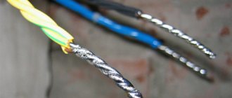
How to connect an inverter if there is no crimped terminal on the cable? Wires are spliced by repeatedly interweaving the wires that make up the core . Then the connection point should be soldered and crimped.
V Abakumov, 5th category welder, Northern Shipyard: “I try not to lengthen the cable. For me, it’s easier to drag the device closer than to bother with braiding and crimping. In addition, the extended one is more likely to get caught and tangled, and there are large current losses on it.”
There are also special extension cables that have crimped and insulated connectors. Their type must match the connector of your device.
Important! Before connecting, all connectors must be thoroughly cleaned with scratch paper and degreased to improve contact.
Manufacturers do not specify any restrictions on cable length. In each case, the welder himself decides what is better - to lengthen or drag the inverter and gas generator more often .
Power supply for inverter welding from a generator
If the facility is not equipped with a stationary electrical network, but welding is still required, you can use a gasoline or diesel generator. The most important thing is to correctly calculate the load so that both devices are optimally combined with each other.
It must be taken into account that any inverter contains coils, capacitors, electronic circuits and other elements that are considered reactive consumers with a power factor of about 0.7. When calculating the total power of the device, it is necessary to divide the active power by the power factor. After preliminary calculations, hardware compatibility will look like this:
- With a welding current of 160 A, you can only work with electrodes with a largest diameter of 4 mm. The active power of such an inverter is 3.8 kW, and the total, taking into account the coefficient of 0.7, will be approximately 5-5.5 kW. Taking into account the 20% power reserve, a generator of at least 6 kW will be required.
- Welding current of 180 A allows work with 5 mm electrodes. Active and apparent power will be 4.8 and 7.5 kW, respectively. Therefore, the generator power should be no lower than 8-8.5 kW.
- If the welding current reaches 200 A, then such equipment needs a three-phase network. The diameter of the electrode increases to 6 mm. The total power of the inverter will be 11.5 kW, and the power of the three-phase generator will be no less than 15 kW.
Marking of welding cables
The welding wire marking consists of several groups of letters and numbers. From it you can understand which model is in front of us.
First there are several letters indicating the type of cable.
After the type, a dash may indicate the climate class of the wire:
Next comes a number indicating the number of cores - 1, 2 or more. The designation is completed by the cable cross-section in mm2.
Safety requirements
When welding work, the following requirements must be observed:
- Do not work with wires with damaged insulation or insufficient cross-section;
- the wire in the working area should be placed freely, without clinging to the welder’s hands or feet;
- there must be enough light in the working area for the welder to move confidently;
- When connecting to the device, polarity must be observed.
Correctly selected wires for a welding inverter are the key to safe and productive work . You need to pay attention to the cross-section, length and climate class of the cable. Cable extension can be carried out in strict accordance with the requirements of the regulations.
Features of winding windings.
There are the following rules for winding the windings of a welding machine:
- Winding should be done along an insulated yoke and always in the same direction (for example, clockwise).
- Each winding layer is insulated with a layer of cotton insulation (fiberglass, electrical cardboard, tracing paper), preferably impregnated with bakelite varnish.
- The terminals of the windings are tinned, marked, secured with cotton braid, and a cotton cambric is additionally put on the terminals of the network winding.
- If the wire insulation is of poor quality, winding can be done in two wires, one of which is a cotton cord or cotton thread for fishing. After winding one layer, the winding with cotton thread is fixed with glue (or varnish) and only after it has dried, the next row is wound.
The network winding on a rod-type magnetic core can be positioned in two main ways. The first method allows you to obtain a more “hard” welding mode. The network winding consists of two identical windings W1, W2, located on different sides of the core, connected in series and having the same wire cross-section. To regulate the output current, taps are made on each of the windings, which are closed in pairs.
The second method of winding the primary (network) winding involves winding a wire on one side of the core. In this case, the welding machine has a steeply falling characteristic, welds “softly”, the length of the arc has less influence on the value of the welding current, and therefore on the quality of welding.
After winding the primary winding of the welding machine, it is necessary to check for the presence of short-circuited turns and the correct number of turns. The welding transformer is connected to the network through a fuse (4...6 A) and if there is an AC ammeter. If the fuse burns out or gets very hot, this is a clear sign of a short-circuited turn.
In this case, the primary winding must be rewound, paying special attention to the quality of the insulation
If the welding machine makes a loud noise and the current consumption exceeds 2...3 A, then this means that the number of turns of the primary winding is underestimated and it is necessary to wind up a certain number of turns. A working welding machine should consume no more than 1..1.5 A current at idle, not get hot and not make a strong buzz.
The secondary winding of the welding machine is always wound on both sides of the core. According to the first winding method, the secondary winding consists of two identical halves, connected counter-parallel to increase the stability of the arc (Fig. 6 b). In this case, the wire cross-section can be taken slightly smaller, that is, 15..20 mm2. When winding the secondary winding using the second method, first 60...65% of the total number of its turns is wound on the side of the core free from windings.
This winding serves mainly to ignite the arc, and during welding, due to a sharp increase in magnetic flux dissipation, the voltage on it drops by 80...90%. The remaining number of turns of the secondary winding in the form of an additional welding winding W2 is wound on top of the primary. Being a power supply, it maintains the welding voltage and, consequently, the welding current within the required limits. The voltage across it drops in welding mode by 20...25% relative to the no-load voltage.
Winding the windings of a welding machine on a toroidal core can also be done in several ways.
Methods for winding the windings of a welding machine on a toroidal core.
| 1. Uniform; | 2. Sectional; |
| a – network winding; | b – power winding |
Switching windings in welding machines is easier to do with the help of copper tips and terminals. Copper lugs at home can be made from copper tubes of a suitable diameter with a length of 25...30 mm, securing the wires in them by crimping or soldering. When welding under different conditions (high or low current network, long or short supply cable, its cross-section, etc.), by switching the windings, the welding machine is adjusted to the optimal welding mode, and then the switch can be set to the neutral position.