Like any electric tool, a rotary hammer requires periodic maintenance. This is largely due to its mechanical parts that need lubrication. But along with this, various types of malfunctions may occur in the device. It is easier to repair damage or carry out preventative maintenance on a tool when you are familiar with the design of the hammer drill and understand the operating principle of its components.
How the tool works
Literally, the word perforator means “drill hammer.” To increase productivity in mining operations, the jackhammer was developed in the early 19th century. The principle of operation of the device was to use a flywheel. He set in motion a bar with special tucks attached to it. The rod, under the influence of a spring, struck and returned back with a piston.
The device was constantly improved. In 1932, in Germany, the Bosch Corporation released the first rotary hammer powered by electricity. This device combined impact and torque. The operating principle developed by the company is still used in modern models of electric hammer drills.
A rock drill is a device designed to drill holes and destroy hard rock. Drills of different diameters and chisels are used as consumables. The tool is divided by application class:
- domestic;
- semi-professional;
- professional.
In addition, it is distinguished by its operating mechanism, which can be electromagnetic or pneumatic. The last type of mechanism is available in one-, two-, and three-mode. That is, you can perform drilling, striking, or both operations simultaneously.
The tool resembles a pistol in appearance and can be operated with an electric, fuel or pneumatic drive. The latter are in demand under hazardous working conditions, during which there is a possibility of explosion.
The operating principle of a hammer drill, which distinguishes it from other similar tools, is based on the impact mechanism. The electromagnetic type uses two electromagnetic coils to provide reciprocating motion of the core. It transfers inertia to the drill shank. The pneumatic type is based on the movement of a piston in a cylinder, which also performs reciprocating movements.
The operation of an electric hammer drill uses the conversion of engine rotation into the shock-rotational movement of the drill. The coupling used in the design provides protection under increased loads. The drill bearing and piston create the impact force, and the drill clamp provides the chuck.
Each manufacturer strives to improve the design through the use of design features. These are mainly minor modifications related to the use of various materials and their location. In general, the main elements remain unchanged. Such details include:
- power button;
- engine;
- impact mechanism;
- safety clutch;
- drill clamp.
Additional design features include a dust removal system and a vibration suppression unit. For a multi-mode type of tool, a work switching button is installed.
Engine location
The power unit of rotary hammers is installed horizontally or vertically. When placed horizontally, the motor axis is parallel to the nozzle. Such models are designed for domestic use; they are occasionally equipped with a motor more powerful than 900 W. Features of the solution:
- light weight;
- compact dimensions except for length;
- ease of maintenance;
- cheapness;
- low heat removal efficiency.
Horizontal position of the tool
A vertical or L-shaped tool is also called a barrel tool. Used in professional hammer drills designed for long-term loads. It has proven itself to be excellent when chiseling floors with vertical grooves.
Peculiarities:
- heavier than horizontal;
- low level of shock vibrations;
- the gearbox needs regular lubrication;
- excellent engine cooling.
Vertical arrangement
Device motor
The engine, being the main element of the device, drives all other parts of the mechanism.
It consists of a stator and a rotor, with the rotor being a moving part and the stator not. The rotor includes an armature and a commutator. An anchor is a block containing steel plates. Windings of copper wire are wound on them. The collector, in turn, looks like a cylinder. Its design has the form of a dielectric with installed conductive plates; the armature windings are connected to these plates. Rotation of the rotor occurs due to the magnetic flux created around it by the stator windings and leading to the occurrence of a torsional moment. In this case, the rotor uses only a constant current value, and the magnetic flux is always directed only in one direction. Power is supplied through brushes made of graphite. The brushes are arranged in such a way as to ensure electrical contact with the armature.
The wear of the brushes should not exceed 70 percent; if it exceeds, they need to be replaced. Before replacing, pay attention to the brush holder and clean it if necessary.
You can use a multimeter to check the windings. To do this, one probe of the measuring device is installed on the brush holder, and the second on the input for connecting to the 220 volt network. To accurately determine the connection locations, it is easier to use an electrical diagram. If the resistance is infinite, it is concluded that the winding has burned out.
Troubleshooting Methods
Self-repair of a rotary hammer is extremely difficult due to its complex design. Even disassembling the case is often an impossible task for a home craftsman.
In addition to appropriate education, specialists from service centers of leading brands have regular work experience, the necessary tools, and equipment.
In addition, a diagnosis of a power tool is made during the initial inspection, which allows you to plan your budget: invest in an existing tool without guarantees of long-term operation, or spend money on a new power tool with a long service life and a manufacturer’s warranty.
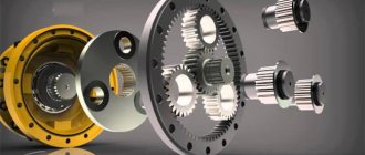
Disassembling the rotary hammer gearbox: 1 – special ring, 2 – releasing sleeve, 3 – ring, 4 – ball, 5 – spring 8 – casing, 22 – closing spring, 28a – switch, 29 – ring, 30 – spring, 31 – latch.
The hammer drill is used in different modes, which significantly reduces the life of the working parts. In addition, specialized companies more often use either slotting (concrete, stone work, restoration of buildings, foundations) or drilling (installation of household and industrial equipment). If in the second case, following the manufacturer’s recommendations on drilling modes, you can extend the service life of the power tool, then in the first option it is very difficult to calculate the load. For example, with a specified maximum concrete drilling of 24 mm, it is recommended to use drills in the range of 18-16 mm. Peaks for breaking concrete, stone, and brick are standard, so the tool experiences different loads.
If the power tool stops hitting, you can limit yourself to disassembling the spindle assembly in the following sequence:
- dismantling the mode switch lever - the parts are usually made of polymers and therefore are quite fragile;
- detachment of the boot - the rubber corrugation must be periodically replaced, since it often comes into contact with destructible materials, wears out, and cracks;
- with a dismountable cartridge, the brushes are first removed; screws are loosened and unscrewed;
- the body is divided into two halves.
Visual inspection in 90% of cases allows you to identify a malfunction and replace the damaged/worn part. Before assembly, lubricant must be added and replaced.
Safety clutch
When the load on the tool increases, exceeding its characteristics according to the operating instructions, in order to prevent damage to the elements, a safety clutch is installed. Its main task is to stop the mechanism from trying to rotate the cartridge when the drill jams. If such a coupling had not been in place, then when jammed, the hammer drill would have been twisted out of the hands.
According to the type of use, clutches can be claw and friction. The first type consists of two parts with beveled edges and connected to each other through a spring. As the pressure increases, the spring straightens and the parts come out of the clutch. The clutch disengages. This condition is characterized by the appearance of a crackling sound. In a friction clutch, the torque is transmitted to the connected mechanism due to the tight compression of the discs. When overloaded, the compression force disappears and rotation is not transmitted.
How to disassemble a hammer drill yourself
- 17-02-2015
- 26
- 2665
A hammer drill is a tool that requires serious consideration during its operation and disassembly. To do this, you need to know its structure, all the components included in the design of the tool. Quick orientation in the device and knowledge of how to disassemble a hammer drill will allow you to avoid unnecessary expenses both financially and labor-wise.
With a hammer drill, unlike a conventional drill, you can drill concrete and other durable materials without any problems.
Any, even the most minor, malfunction of the device can lead to more serious breakdowns. Step-by-step disassembly will allow you to quickly find if a tool is broken. It is important to know the cause of the breakdown and ways to eliminate it. Disassembling a tool requires following a certain sequence.
Step-by-step disassembly of a rotary hammer with your own hands
To begin with, the upper assembly of the hammer drill is inspected, which is first disassembled into its components. All parts are removed in the following order:
- Tip.
- Washer.
- Spring.
- Ball.
When the last part is removed, you will need to unscrew all the screws holding the housing in place. Next, remove the cover on the handle, if present, after which you need to disconnect each wire from the starter. Then the brush holder is removed.
Diagram of the hammer drill device.
At the next stage, the gearbox and housing are disconnected until a gap appears through which the switch should be removed. Next, the device should be fixed in a vertical position using a vice. This will allow you to get all the parts out of it.
You can use the services of the appropriate service to disassemble the hammer drill. By doing this yourself, you can save a lot of time and money on equipment repairs. When performing work, you should follow the step-by-step instructions:
- Disassembly begins from the top assembly, after first removing the tip, washer, and at the end - the spring with the ball.
- When the ball is removed, you can begin to unscrew the screws that hold the body in place.
- After this, remove the cover on the handle, if present, and then disconnect each of the starter wires.
- Remove the brush holder.
- Disconnect the gearbox from the housing until a gap is formed so that the switch can be removed.
Impact mechanism
This part of the tool provides the main task of the hammer drill - to chisel. The type of operation can be mechanical or pneumatic.
There are two design options for a pneumatic mechanism : using a rolling bearing or a crank type. The first option is used for a household type of tool, and the second - for a professional one.
A device using a rolling bearing, or otherwise a “drunk bearing,” consists of a group of elements: a piston, a firing pin, a ram and the bearing itself.
The rotation of the engine during operation is associated with the inner sleeve of the “drunk bearing”. The outer sleeve is connected to the piston and performs a rolling motion. The distance between the piston and the ram is filled with air. It, subject to changes in pressure, acts on the ram, which repeats the movements behind the piston. As a result, a blow is struck to the striker, which, in turn, transfers the force of the blow directly to the drill. This action actually means the conversion of electrical energy into mechanical energy.
Disassembly and assembly of gearbox P710
Remove in sequence: - special ring 1, - release sleeve 2, - ring 3, - ball 4, - spring 5. Pull the bearing shield out of housing 8 by 3-4 mm, remove switch 28a. Remove the bearing shield from the housing. Remove in sequence: - clamp 31, - spring 30, - ring 29. Remove closing spring 22.
Remove in sequence: - spring 21, - locking bar 20, - front switching bar 17, - rear switching bar 18, - spring 19 from the axle.
Remove washers 10, 16 and 55, spindle assembly and intermediate shaft 50 from bearing shield 24. Remove washer 43 and springs 42. Remove bearing 51. Remove gasket 26. If necessary, remove from bearing shield 24: bearing 23, bearing 52. Note: Washer 10 serves to ensure mounting distances and may be missing on some machines.
Remove ring 11, washers 12, spring 13 and gear wheel 14. Remove cylinder 40 with piston 38. Remove piston 38 from cylinder 40. Remove ring 37 from spindle 15. Remove sequentially: - catch sleeve 35, - rubber washer 34, - impact intermediate body 33. If necessary, remove rings 32, 36, 39. Remove axle 41 and washers 27.
Remove, in sequence, the intermediate shaft gear 44 and the switching bushings 45 and 46. Remove the large intermediate gear 49 and the swing bearing 48 from the intermediate shaft 47. Tools: rack press, gasket, mandrel.
Apply grease 5 to the intermediate shaft 47 in an amount of about 1 g. Press in successively the swing bearing 48 and the large intermediate gear 49. Assemble in sequence the switching bushing 46 and the gear wheel of the intermediate shaft 45. Tools: rack press, bushing (pipe) with inner diameter 8 mm.
1. Apply grease to the cylinder bore 40. 2. Assemble washers 27 and axle 41. 3. Insert ring 39 into piston bore 38. 4. Apply grease to the cylinder bore and to the piston. 5. Insert piston 38 into cylinder 40.
1. Install rings 32 on the intermediate striker 33. 2. Insert ring 36 into the channel of the clamping sleeve 35. 3. Place in sequence: - spindle gear wheel 14, - spring 13, - washers 12, - ring 11 on spindle 15. Into the spindle in series insert: - intermediate striker 33, - rubber washer 34, - clamping sleeve 35, - ring 37. Note: Clamping sleeve 35 is inserted with a large chamfer into ring 37. Tools: rack press, pliers and mandrel for pressing ring 37, sleeve for pressing ring eleven
Install the intermediate switch bar 18 on the switch bar 17 and the spring 19 so that the spring is between the intermediate switch bar 18 and the switch bar 17, as shown in the figure. On axis 53 install sequentially: - spring 21, - locking bar 20, - switching bar 17 together with intermediate switching bar 18 and spring 19.
Install bearing 23 and bearing 52 on bearing shield 24. Install the spindle assembly on the bearing shield and measure the mounting clearance. With a gap of 92.38. 92.7 install washer pos. 10. With a gap of 92.7. 93.32 - washer pos. 10 is not installed.
Insert the cylinder with piston 40 into the bearing assembly shield 54.
Install the bearing assembly 51 on the intermediate shaft 50. Assemble the bearing shield 54, the intermediate shaft assembly and the bearing assembly 51 so that the thrust bearing axis fits into the hole of the cylinder axis, as shown in the figure.