Many articles on the Internet and in print publications are devoted to the installation of such parts, in my article about choosing the main tool, I already wrote a little on this topic
. Now I want to complement it. I hope my opus will be useful for beginners and for those who have not yet dealt with such components.
The publication of the article is timed to coincide with the release of the first Datagor constructor
, where there are 4 such elements, and the PCM2702 processor itself has super-small legs.
The supplied printed circuit board has a solder mask
, which makes soldering easier, but does not eliminate the requirements for accuracy, absence of overheating and static.
The subtleties of good soldering
To solder a part to the board, you need:
1) Apply flux to the soldering surface; 2) Tin them with solder; 3) Apply flux to the contacts again; 4) Solder the gap between the contacts.
The first important rule is to avoid temperatures above 400°C or more. Many beginner (and even experienced) radio amateurs neglect this. These are critical values for microcircuits and boards.
Solder melts at approximately 180 to 230°C (lead-containing solders) or 180 to 250°C (lead-free). This is far from 400 °C. Why then set the temperature high?
What you need for reliable contact
Main criteria:
- Choose the right flux. For example, liquid flux is suitable for soldering wires. It wets wires best and allows for better tinning of such contacts. Low-quality flux quickly boils and spreads over the board.
- Use high quality solder. It is the solder that determines the further reliability and strength of the connection. Also, the quality of the solder can affect the operation of the circuit as a whole; due to slag and low-quality alloys, interference may occur in the operation of the electronics and, over time, cracks may appear.
- Use proven tools and equipment. Soldering irons of poor quality can maintain temperature unstably and overheat.
- Maintain temperature conditions. Do not overheat the parts and stay within the melting temperature of the solder. The temperature is too low and the solder will not melt well, and if it is too high, the material will evaporate, making it worse to tin the contacts.
- Long hours of practice, trial and error. Without practice, there will be no soldering method.
These criteria are interrelated with each other. And with a poor choice of components and materials, the same result will occur.
Sequence of actions using the example of an SMD component
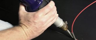
Let’s say that on the working printing surface of the electronic unit being repaired there is a burnt-out SMD box that needs to be dismantled. To remove it and install a new one, you need to select a compact nozzle for the hair dryer and prepare flux.
The temperature regime on the soldering hair dryer is set within 345-350 degrees using a regulator. Then they apply flux to the part to be replaced, and begin to slowly “warm up”.
The air pressure during the process should not be too strong, otherwise there is a risk of blowing away nearby elements. The culprit of the breakdown continues to be heated until the solder begins to melt, which will be immediately noticeable.
It may take about three minutes to warm up, and this is normal, there is no need to rush. If the solder persists for a long time, you need to add 5 degrees.
After the solder has liquefied, carefully dismantle the SMD part. During the process, it is important not to knock down the neighboring components, since they have probably lost stability due to the melting of the solder holding them in place.
Upon completion of the operation, the copper braid must be used to clean the “spots” (contact pads), then provide small bumps in the same places with solder paste or solder.
A serviceable smd is placed in the old place with a minimum amount of flux. Heat the part with a soldering hair dryer until the solder shines brightly, spreading over each of the contacts.
Where to begin
First, you need to decide for what purpose you need soldering. For amateur radio, this is an entry-level level; for soldering wiring and a simple level, more professional tools are needed. And to repair and solder SMD and BGA microcircuits, you will have to learn all the basics of soldering and purchase special tools and consumables.
Choosing the Right Soldering Kit
Solders come in different types and diameters.
A large solder diameter is convenient for soldering wires, and small diameters are suitable for spot soldering SMD components or connectors. Solders also come with or without rosin. With rosin, solder is very convenient. It is easiest to use it on a soldering iron tip.
Starter Kit
For radio amateurs, stores sell everything at once in one pack. Such sets are the cheapest, since everything will cost more separately. For example, there are sets with a soldering iron and tips, as well as tweezers.
Soldering iron or station
For soldering radio components and wires, a simple soldering iron with a copper tip is sufficient. But for more advanced soldering you will need a station. A soldering station usually consists of a hair dryer and a soldering iron. Using a hair dryer, you can solder SMD components, and you will be able to warm up the board better.
It is best to start with a soldering iron and choose one that has temperature control and changeable tips.
Soldering iron tips
There is an arsenal of tips for soldering irons. Cone, flat, hatchet, wave, etc. They can all be of different sizes and shapes.
Soldering tip selection
A mini wave is perfect for beginners. This type of tip is the easiest to tin and is capable of a wide range of tasks.
Features of application
For soldering wires these are massive tips, and for planar contacts these are usually conical and curved tips. For example, to solder a cable from a board, a hatchet is best suited. This type has a wide working surface, which allows you to massively heat a large surface of the board.
Eternal stings and rules for their use
The main rule when using permanent tips is that there should always be solder or flux on the tip. If you ignore this rule, black dots will begin to appear on the sting, which will eventually spread to the entire surface.
This is a layer of soot that forms when air oxidizes on the working surface. Solder or flux perform a protective function, and during operation of the soldering iron they, and not the soldering iron tip, are oxidized.
Why did the soldering iron start to solder poorly?
If the soldering iron melts the solder, but does not take it to its working surface, then it needs to be tinned. It is highly oxidized, but should not be thrown away.
Preparing for work
After turning on the soldering iron, you need to wait for it to heat up. All preparation comes down to cleaning carbon deposits from the working surface and applying solder. When working with stings, do not use cutting tools. Do not remove carbon deposits from the soldering iron with blades or other sharp objects.
Soldering iron tinning
Tinning a soldering iron occurs in stages:
- The heated tip needs to be cleaned. Using a wet sponge or copper shavings.
- Solder was applied to a clean surface.
The black surface of the tip is removed by long tinning. This is done using a lump of solder and flux. The tip is drowned in solder until it is clean. Periodically it should be dipped in solder. And then clean again with a sponge. In this case, it is best to use copper shavings; they remove oxides and carbon deposits much better. A wet sponge only removes solder, not carbon deposits. If the above methods do not help, then you will have to use a tip activator or soldering acid.
Hair dryer nozzles
The soldering gun also has its own attachments. They come in different diameters, shapes and fastenings. It all depends on what kind of work is being done.
Soldering flux selection
Soldering work has a wide range. And different tasks require different materials. For example, for soldering wires, nothing beats regular rosin. Rosin is cheap, practical and easy to use. But for microcircuits a different approach is needed. Paste-like flux and syringe for precise dosing of flux to SMD components.
How to clean flux after soldering
Using Galosh gasoline or alcohol.
Tools and consumables for cleaning:
- Cotton wool;
- Cotton pads;
- Cotton sticks;
- Toothbrush.
Workplace and additional tools
A wooden table is suitable for the workplace. If you don’t want to spoil the surface of the table, you can use a wooden plank. Wood absorbs little heat and does not act as a radiator. And if you don’t have such a board, you can purchase a silicone heat-resistant mat. This mat has a convenient area for disassembling electronics, various pockets and places for tools. The mat can be cleaned with regular alcohol after use if there are any stains or traces of solder.
Tweezers and spatulas
Using tweezers, you can move parts when soldering, position and install parts. They are also made from different materials, they can be angular, straight, with fixation, etc.
Optics and microscopes
Magnifiers are not very convenient, so it is much more convenient and practical to use microscopes. It's best to start with a budget option. For example, a simple USB microscope will allow you to evaluate the result of soldering on a computer screen.
Of course, the frame rate does not allow you to work normally under it, but it allows you to examine small details of the board without harm to your eyesight.
Room ventilation and safety rules
The room must have good ventilation. When soldering, you need to keep your distance and not get too close to avoid solder getting on your face. After soldering work, be sure to ventilate the room and wash your hands and face with soap. You should not eat food while soldering, because smoke residues remain on mucous surfaces.
Dismantling techniques
The method of soldering microcircuits depends mainly on the type of pins, although there are universal methods.
Dismantling the microcircuit with a soldering iron
This is the most time-consuming and unreliable method. It is used only when the number of microcircuit legs is minimal. Before soldering microcircuits with a soldering iron, the tip of the tip is carefully tinned and cleaned of solder residues so that it remains only in the form of a thin film. The molten solder that surrounds the IC leg is transferred to the tip under the action of tension. By repeating the procedure several times, the leads are completely released.
Important! Before each touch of the board, the tip is cleared of solder. The touch time should not be more than three seconds. If the leg is not completely freed, you can only work on it after some time has cooled down. At this time, you can make the following conclusions.
Removing the chip using a razor blade
When working with planar elements, an ordinary razor blade will come to the rescue. For convenience, the razor blade is broken in half lengthwise. Leaning the blade close to the border of the terminal and the board, heat the scion until it melts. By inserting a blade between the leg and the board, they are separated. The blade is made of stainless steel, so solder does not stick to it.
Using dismantling braid
The special dismantling braid works thanks to the capillary effect, drawing in the molten material. You can use braided shielded cable with the same effect. The braid must be clean, without traces of oxidation. In order to improve the spreading of the melt, the braid is moistened with liquid flux.
Dismantling microcircuits using a desoldering pump
The desalination pump is a special piston that, when moving, draws in the melt, releasing the outlet. This method is suitable for working with DIP and SIP components.
Using medical needles
This method has proven to work best when dismantling ICs, especially for single-sided printed material. Double sided PCB can also be used to remove needles from syringes. When choosing a needle, you need to ensure that its inner diameter allows the leg of the microcircuit to fit freely, and its outer diameter allows it to fit into the hole on the printed circuit board. The tip of the needle is ground with a file until a smooth surface is obtained.
The needle is placed on the tip of the leg and the terminal is heated with a soldering iron. After the solder has melted, the needle is inserted into the hole of the board and smoothly rotated around the axis until the tin solidifies. After this, the needle is removed from the stem, which is now completely free. The needle material (stainless steel) is not tinned, so rotation around the stem is only necessary to make it easier to remove it from the hole.
Use of alloy rose
Using a rose alloy, you can desolder all the terminals of the IC at the same time, due to the fact that the low-melting alloy spreads between the terminals and evenly and simultaneously transfers heat to all of them from the heated soldering iron tip. After complete heating, the part is carefully removed from the board using tweezers.
This method has one disadvantage - after dismantling, it will not be possible to collect the remaining rose alloy, since it will be clogged with excess tin and lead, which will change its composition and melting point.
How to desolder a microcircuit from a board with a hairdryer
When working with SOJ, PLCC, QFJ and BGA packages, a soldering station or hair dryer with temperature control is required. Using the station, the entire section of the board is heated until the microcircuit is released, and using a hair dryer with a nozzle, a stream of hot air is directed to the terminals of the IC until they are released.
Radioelements must be desoldered at a temperature of 250⁰C. To prevent overheating, adjacent elements should be covered with aluminum foil.
How to remove capacitors from a motherboard
To desolder capacitors or other two-terminal elements, there is no need to use a special soldering tool. During the dismantling process, one of the terminals of the capacitor is heated, while simultaneously tilting the element so that the leg comes out of the hole. Next, repeat the same with the second leg, tilting the part in the opposite direction. To avoid tearing, do not press hard on the capacitor. By warming up both terminals in turn, they are gradually released.
Simple soldering of wires
The first example is soldering wires.
What you need
To strip the insulation from the wires you will need a stripper.
It can be used to quickly remove insulation. Side cutters, wire cutters, a knife, teeth or a soldering iron will not be able to cope with this task as easily.
Liquid rosin, or FKET, is suitable for soldering wires.
Liquid rosin best coats the wire veins. It is cheap, practical and convenient.
Which sting is better to choose
Wires require a lot of solder. A mini wave is more practical for soldering any wires than a regular cone or flat tip.
Step by step process
We remove the insulation with a stripper and twist the wires.
We apply flux to the wires to be soldered, and take the solder onto the tip. The temperature of the tip is no more than 300 °C.
With several movements back and forth we tin the twisted wires. If the solder has formed into lumps, then add it and wait for the soldering area to cool down so as not to damage the brush. Add more flux and run the soldering iron over the soldering area again. There should not be much or little solder.
It's best to tin both wires before soldering them together, but you won't be able to twist them together securely. Therefore, it is easier to immediately twist and then solder them.
Headphone repair
The main problem when repairing headphones is the resistant insulation of the wires.
Features of wire tinning
To tin such wires, you need to carefully walk over the soldering area using solder and rosin.
For soldering you will need a massive tip, a large drop of solder and liquid rosin. Flux is applied in the same way, but soldering is a little different. Now the main task is to burn the insulation. This can be done with a large drop of solder. Using longitudinal movements back and forth, apply solder to the soldering area. Insulation burns slowly. There is no need to raise the temperature above 300 °C or use acid. If we can’t tin, then we try again, but instead of rosin we use LTI-120. This flux will help tin the wires no worse than soldering acid.
Tinning of enameled wire
Enameled copper wire has a heat capacity and is difficult to tinning.
But it can be easily tinned using ordinary rosin. Sandpaper is enough.
We remove the enamel coating using sandpaper, apply rosin and the wire is successfully crimped and ready for soldering.
Soldering LED strip
The LED strip has the same heat capacity as a thick wire. It contains a copper substrate, which absorbs heat when heated.
We tin the contacts using rosin. We use a mini wave and very little solder. There should be some solder at the soldering area.
Next, we take the soldering iron away from us with the handle, lean the wire against the contact and on top with the tip of the soldering iron. Soldering should take no longer than a second while there is flux. This is due to the fact that the copper substrate quickly absorbs heat, and the burning flux is no longer able to assemble the solder into a single whole. Therefore, if soldering work lasts more than a second, then there will be lumps of solder on the tape with signs of cold contact. If this happens, apply flux again and correct the bad soldering with one touch.
Rosin (flux) can be cleaned from the tape using alcohol (or gasoline) and a cotton pad.
Main conclusions
Soldering SMD LEDs is not very difficult, but requires care and caution. You should remember the danger of overheating of the elements, which will result in their failure. It is necessary to ensure compliance with the following conditions:
- use a low-power soldering iron with a heating temperature no higher than 260°;
- use high-quality flux (experts recommend a special composition for soldering aluminum);
- limit the contact time of LEDs with the soldering iron tip.
In addition, you must remember to maintain polarity and monitor the condition of the current-carrying paths. Please share your options for soldering SMD LEDs in the comments.
Educational program for beginners
To desolder a part from a board, you need to make sure that the contacts are heated until the solder melts (approximately 230 °C). The main mistake beginners make is to immediately heat the place where they are soldering to 300 - 350 °C.
For example, you need to desolder a microcircuit from a board using a Lukey 702 soldering station.
Many radio amateurs and electronics engineers set heating parameters above 300 °C.
At the first moment, the part is exposed to about 200 °C. The contacts and the surrounding area of soldering work are at room temperature.
The heating of the part reaches 300 °C, but the contacts have not yet reached 200 °C.
The microcircuit experiences a critical temperature of 350 °C. Meanwhile, the surrounding soldering area is heated unevenly, even if the hair dryer is evenly moved across the soldering area. A noticeable temperature difference appears at the contacts of the part.
400 °C and the microcircuit begins to fry.
A little more, and it will unsolder due to the fact that the contacts have practically heated up until the solder melts. But this happens because the board has warmed up. And in this case, it happened unevenly. High temperatures lead to thermal breakdown of the microcircuit and it fails. The board bends, turns black, and bubbles appear due to boiled PCB and its components.
This soldering method is very dangerous and ineffective.
How do you solder parts without damage?
It is necessary to analyze the soldering area and equipment:
- Estimate the thickness of the board. The thicker the board, the more difficult and longer it takes to warm it up. The board consists of layers of tracks, masks, pads and many metal parts that are very heat-intensive.
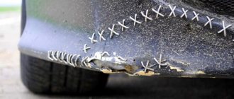
- What's nearby? To avoid damaging surrounding components, they must be protected from temperature. The following will cope with this task: thermal tape, aluminum tape, radiators and coins.
- What is the ambient temperature ? If the air is cold, the board will have to be heated a little longer. Of particular importance is what is located under the board. No need to solder on a metal plate or on an empty bench. A wooden board or a set of napkins works best. And at the same time, the board must be in the same plane, without distortions.
- Equipment. Many soldering stations are sold without calibration. The difference between the temperature shown on the indicator and the actual temperature can reach either 10 °C or 50 °C.
Tools and materials
A few words about the tools and consumables necessary for this purpose. First of all, these are tweezers, a sharp needle or awl, wire cutters, solder; a syringe with a fairly thick needle for applying flux is very useful. Since the parts themselves are very small, doing without a magnifying glass can also be very problematic. You will also need a liquid flux, preferably a neutral no-clean one. In extreme cases, an alcohol solution of rosin is also suitable, but it is still better to use a specialized flux, since the choice of them is now quite wide on sale.
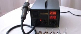
In amateur conditions, it is most convenient to solder such parts using a special soldering hair dryer or, in other words, a hot-air soldering station. The choice of them on sale now is quite large and the prices, thanks to our Chinese friends, are also very affordable and affordable for most radio amateurs. For example, here is a Chinese-made example with an unpronounceable name. I have been using this station for three years now. So far the flight is normal.
And of course, you will need a soldering iron with a thin tip. It is better if this tip is made using the “Microwave” technology developed by the German company Ersa. It differs from a regular tip in that it has a small depression in which a drop of solder accumulates. This tip makes fewer sticks when soldering closely spaced pins and tracks. I highly recommend finding it and using it. But if there is no such miracle tip, then a soldering iron with a regular thin tip will do.
In factory conditions, soldering of SMD parts is carried out using a group method using solder paste. A thin layer of special solder paste is applied to the contact pads on the prepared printed circuit board. This is usually done using silk-screen printing. Solder paste is a fine powder of solder mixed with flux. Its consistency is similar to toothpaste.
After applying solder paste, the robot places the necessary elements in the right places. The solder paste is sticky enough to hold the parts. Then the board is loaded into the oven and heated to a temperature slightly above the melting point of the solder. The flux evaporates, the solder melts and the parts are soldered into place. All that remains is to wait for the board to cool down.
You can try this technology at home. This type of solder paste can be purchased from cell phone repair companies. In stores selling radio components, they also usually have it in stock now, along with regular solder. I used a thin needle as a paste dispenser. Of course, this is not as neat as, for example, Asus does when it manufactures its motherboards, but here it is. It will be better if you take this solder paste into a syringe and gently squeeze it through a needle onto the contact pads. You can see in the photo that I went a bit overboard by plopping down too much pasta, especially on the left.
Let's see what comes of this. We place the parts on the contact pads lubricated with paste. In this case, these are resistors and capacitors. This is where thin tweezers come in handy. It is more convenient, in my opinion, to use tweezers with curved legs.
Instead of tweezers, some people use a toothpick, the tip of which is slightly coated with gumboil to make it sticky. There is complete freedom here - whatever suits you best.
How to solder with a hairdryer correctly
It is necessary to cover all small components that are vulnerable to overheating with protection.
In this case, aluminum tape is used. It protects components well from temperature and holds the board components tightly. However, it adds heat capacity to the soldering area. Thermal tape also protects well, but sticks to the board less well.
The board is placed on a material that has the least heat capacity and slowly releases temperature to the environment. You can use, for example, a wooden plank. And at the same time, the soldering area should not be inclined.
It is best to apply flux to the contacts. It distributes heat well compared to heated air, but you should not add too much of it. It may boil, hiss, or interfere with soldering.
The first step is to warm up the soldering area. The hair dryer is set to about 100 °C and maximum air flow.
It is necessary to warm up both the part itself and the surrounding soldering area with contacts in a circular motion.
Next, after about a minute, you should gradually increase the heating.
The difference with the contacts will be small. Thus, within a few minutes, increase to 300 °C.
Steps of about 20 - 30 °C for every tens of seconds.
How to understand that a part is already soldered
A glare appears on the contacts. Using tweezers, gently push the chip. If it moves easily and smoothly from side to side, then it can already be removed; if not, we heat it further.
This technique must be individually adjusted for each soldering and soldering station. For example, sometimes you will have to heat the board longer, and sometimes about 240 °C will be enough. The soldering method depends on the case.
Structure of diode elements
The main difference from other lamps is that LEDs have a positive and negative contact (anode and cathode)
When soldering a diode in a circuit, it is important to take this into account
You also need to understand that there are DIP and SMD LEDs.
The positive contact in DIP is determined quite simply. It is worth taking a close look inside the flask. The positive terminal - the anode - is smaller than the negative one. In the picture, the plus is on the left.
There is a second way - look at the length of the leg. It is longer at the positive terminal.
The third way is with a multimeter. The black terminal of the device is negative, the red terminal is positive. Let's call:
The last method is suitable for both types.
This is perhaps the most important thing to know about the structure of an LED. If you are interested in the theory, we recommend watching the video:
Alloy Rose
To reduce the risk of overheating, Rose alloy can be used. It will help reduce heat to 120 °C. In this way, you can remove the part from dangerous and sensitive areas. Just add a couple of solder granules and a little flux.
After tinning the contacts, the part is easily desoldered. You need to carefully desolder the contacts; they can easily be damaged due to sudden movement.
The resulting solder must be removed from the board. It is very fragile and not suitable for use.
Combined method
Another very effective technique. If during soldering the part is poorly soldered or does not desolder, this is a consequence of low-quality solder, flux, or insufficient heating of the board.
To do this, while working with a soldering iron, you need to help from above with a soldering hair dryer. The hair dryer should be set to 200°C. This way, heating will occur faster, and the temperature at the contacts will stabilize, and the surrounding air will absorb less heat.
Lukey 702 – budget option
A soldering gun, which is part of the station of the same name, equipped with a classic soldering iron and a control unit. Smooth adjustment by mass air flow is provided. There is a function for setting the required temperature.
The location of the turbine-type compressor in the handle made it possible to save space, reduce the overall dimensions of the device, and improve internal thermodynamics. The sound produced by the supercharger has been significantly reduced. Sleep mode is activated automatically when the device is placed on the stand.
Pros:
- Wide functionality, availability of a standard soldering iron.
- Performance, temperature range.
- Price for such technical capabilities.
Minuses:
It fluctuates with temperature, needs to be calibrated. At first glance, the design is flimsy.
In what cases will soldering with a hairdryer not work?
A soldering gun usually reaches a power of no more than 500 W. The lower the power, the less the board area can be heated.
Using a soldering gun will not adequately desolder massive parts or computer BGA chips (bridges, CPU, GPU). A hairdryer will not be able to warm up such areas.
It's like boiling a glass of water with one match. Increasing the temperature is also not an option; this will destroy both the part itself and the board.
A massive board requires bottom heating. Most often this is a stove that heats up to 100 - 200 °C. The printed circuit board will be heated evenly. And use a hair dryer to bring the solder to melt.
You can also use a hair dryer. It has a larger nozzle and its power can be up to 3000 watts. However, a hair dryer is not a solution either. Due to the fact that only the part and a small surrounding space around it are heated, after soldering the board is deformed due to the high heating difference, thereby tearing off the leads from the pads (this is especially true for large BGA parts).
Heating from below
This technique is not only useful when working with a soldering gun, but also increases the convenience of soldering.
The board is secured with a clamp, the temperature is set to 200 degrees and warmed up for five minutes, after which they begin to work as usual.
Using thermal tape, you can shield nearby elements.
After removing the chip, the contacts are cleaned with the above braid. Do the same with the board.
All procedures must be carried out carefully to prevent damage to the circuit. If you don't have copper braid on hand, you can remove the solder using a soldering iron with a thin tip.
Soldering parts from boards with one soldering iron
Small-sized SMD parts can be desoldered using a conical tip. Both contacts of the part heat up and it quickly comes off the board. Also, a conical tip is convenient when soldering SMD parts, since you can accurately dose the amount of solder onto the contacts.
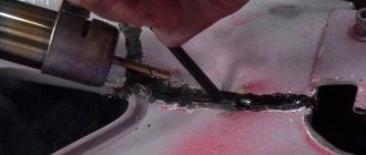
Braided soldering
Braid consists of strands of thin copper wires.
You can use shielding insulation from the antenna as a braid. Using a braid, you can quickly and easily remove solder from a contact. It is necessary to apply flux to the braid and contact. Next, using a soldering iron, the soldering area is slowly heated and the tin is transferred to the braid. This soldering method is good for small parts and small DIP contacts. If you need to unsolder the PCI connector, then the braiding will quickly be wasted.
Vacuum syringe and needles
The vacuum syringe quickly removes massive burnt parts of solder. And with the help of DIP needles, the contacts are easily unsoldered from the board. The needle is put on the contact and heated up using a soldering iron. You need to have time to pass the needle through the board contact onto the microcircuit body while the solder is in a molten state. Or vice versa, when the contact is already warmed up, and at the same second the needle is inserted.
Such soldering methods are outdated. Modern boards are manufactured for machine assembly, so the gap between the contacts and pins of the parts is minimal. The needle is already weak, and the vacuum syringe does not have time to pick up the sharp drops of solder. It is no longer possible to desolder a regular electrolytic capacitor using a syringe. In this case, the liquid sting method will help.
Liquid sting and its advantages
The liquid tip is a drop of solder, which allows you to avoid using additional tools (braid, hair dryer, needles or syringe). The technique is the same as with the Rose alloy. The main difference is in temperatures.
The hatchet-type sting has a massive longitudinal working surface. It allows you to capture multiple contacts at once.
Apply solder to the tip.
A paste-like flux is applied to the chip to be soldered using a syringe.
The part and its contacts are heated with a sting until the tin melts, and the same must be done on the other side.
Using this technique you can also remove DIP contacts.
Chip types
The wide variety of microcircuit packages has led to the fact that soldering techniques began to differ. Previously, the most widespread were microcircuits with pin pins for mounting into holes on a printed circuit board. Subsequently, with an increase in the degree of integration and the widespread use of automated soldering lines, surface mount elements with flat or ball leads began to be used.
ICs (integrated circuits) with solder pins are typically DIP and SIP packages with two and one row of pins, respectively.
Surface mounting ( SMD ) allows installation of ICs with pins of the following types:
- Flat leads brought outside the housing - SOIC, SOP, QFP (square housing);
- Flat legs, bent inward, under the body - SOJ, PLCC, QFJ;
- Ball terminals - BGA.
Each variety has several subspecies. The total number of housing types is in the dozens.
Additional training
For additional training, you can try soldering various unnecessary boards from computers and smartphones. There are many SMD and DIP components on motherboards. Only long and hard hours of practice will help you develop your soldering skills.
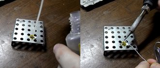
Net
As an exercise, you can try soldering a grid of wires. The quality of soldering is assessed by the load on this soldered wire mesh. If the solder joints do not break under load, then the soldering is excellent.
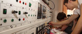
Constructors
Radio designers are also a great help.
They teach you to understand electrical circuits and the intricacies of soldering. You should start with simple constructors, such as flashing lights or door locks. As your skill increases, you can increase the level of difficulty, reaching complex LED cubes.
Soldering with acid
Acid is used only as a last resort, when a heavily oxidized surface cannot be tinning. All parts, wires and connectors can be perfectly soldered without acid. More about soldering acid
We remember the school physics course
In order to solder LEDs (for example, SMD type), you need to know what some of the signs on the circuits mean. Namely:
- "U". This letter on all electrical diagrams indicates voltage. It is measured in V (volts);
- "I". Under this designation lies the current. It is measured in A (amps);
- "R". This letter means the electrical resistance of the circuit elements. This indicator is measured in Ohms (ohms).
All of the above values reflect Ohm's law, which is described by the following formula:
In addition, you need to understand that under the letter “P” is power, which is measured in W (watts). Power is determined by the following formula:
The decoding of these values must be known in order to correctly solder LEDs into any circuits and boards.