What is needed for work
A soldering gun, also called a hot-air soldering station, is a multi-component tool with a large number of functions for repairing modern devices. It allows you to solder SMD components, capacitors, LEDs and other parts. The same applies to BGA-type chips, which make installation more dense. Today, almost every electronic component in modern devices is made in this way.
To solder SMD components, you need the following materials and devices:
- actually, the hair dryer itself;
- attachments for it;
- flux with solder paste;
- copper braid;
- some kind of device for prying up parts (tweezers, for example);
- medium-soft brush;
- lens;
- a soldering iron with a thinner tip compared to a standard one;
- stencil for “rolling”.
To work competently with a soldering gun means to be careful, have angelic patience, and be extremely careful.
Required materials and tools
To solder SMD LEDs you will need:
- soldering iron with the necessary parameters;
- side cutters, tweezers, scissors;
- mounting needle or thin awl;
- solder and flux. Regular rosin or a special liquid composition, which is an alcohol solution, will do. An aspirin tablet is often used;
- thin brush for applying liquid flux;
- a magnifying glass on an adjustable stand (bracket), which is used by jewelers;
- soldering gun (component of a soldering station).
Sequence of actions using the example of an SMD component
Let’s say that on the working printing surface of the electronic unit being repaired there is a burnt-out SMD box that needs to be dismantled. To remove it and install a new one, you need to select a compact nozzle for the hair dryer and prepare flux.
The temperature regime on the soldering hair dryer is set within 345-350 degrees using a regulator. Then they apply flux to the part to be replaced, and begin to slowly “warm up”.
The air pressure during the process should not be too strong, otherwise there is a risk of blowing away nearby elements. The culprit of the breakdown continues to be heated until the solder begins to melt, which will be immediately noticeable.
It may take about three minutes to warm up, and this is normal, there is no need to rush. If the solder persists for a long time, you need to add 5 degrees.
After the solder has liquefied, carefully dismantle the SMD part. During the process, it is important not to knock down the neighboring components, since they have probably lost stability due to the melting of the solder holding them in place.
Upon completion of the operation, the copper braid must be used to clean the “spots” (contact pads), then provide small bumps in the same places with solder paste or solder.
A serviceable smd is placed in the old place with a minimum amount of flux. Heat the part with a soldering hair dryer until the solder shines brightly, spreading over each of the contacts.
Making a hair dryer for a soldering station
It is the hair dryer, which supplies hot air to the surfaces being treated, that is the main component of a homemade station. Therefore, first of all, we will talk about the manufacture of this part. We need to perform a few simple steps:
- We select a suitable ceramic tube and wind a nichrome spiral onto it. The thickness of the wire and the number of turns should be such as to provide power within 400-500 watts.
- We insulate the resulting heating element with fiberglass. It is best to wind several layers of this material at once to prevent oxidation of metal surfaces and minimize the risk of equipment overheating.
- At the outlet of the tube we install an insulator, which can be used as ceramic chips from a broken iron.
- We will equip a pressurization system. For this purpose, coolers from a laptop or PC, and fans from a household or hair dryer are used. To make the device operate as efficiently as possible, it is advisable to consider controlling the intensity of the air stream and the engine rotation speed.
- We install a thermocouple to control the temperature of the supplied air.
If you do not want to spend time and effort making a hair dryer, you can purchase this device separately from the soldering station. But in this case, additional financial costs will be required. The option proposed above can also be made from improvised means.
Features of working with BGA chips
When soldering BGA type microcircuits, the same temperature range is selected from 345 to 350 degrees, ensuring moderate air pressure to prevent blowing off the “neighbors”. During operation, the soldering gun should be held at an angle of 90 degrees with respect to the board. To avoid failure of the chip, you should not heat it only in the center; it is better to go around the mounting element around the perimeter.
After 1-3 minutes have elapsed, you can try to slightly lift the chip above the board using tweezers. If the chip does not budge, the solder is still hard. To avoid damage to the conductive paths of the board, you need to use the regulator on the hair dryer to “throw on top” 5 degrees of temperature and continue heating.
Infrared
It is also quite possible to make an infrared station yourself. For this purpose you will need:
- soldering iron;
- PC power supply;
- car cigarette lighter.
You can use the old power supply. You only need one working line with a voltage of 12 volts. No special power required. The only thing you need for a soldering iron is a wooden handle. It can be used from any other device or made independently. The first step is to disassemble the cigarette lighter to get to the heating element that is located inside. The photo shows what it looks like.
The next task is to attach the cigarette lighter handle to the soldering iron handle. You can use glue for this. Next, you need to drill a hole in the cigarette lighter handle so that the power wires can be fed through the hole. Once the wires are connected, you can assemble the cigarette lighter module with a ceramic spacer, as shown in the photo below.
The entire structure can be secured to the handle using an additional metal plate. When everything is ready, the wires are connected to the power supply to a 12 volt output. The finished version of the mini-station is shown in the photo below.
The station turns out to be compact, so it is easy to transport and can be powered from any source that is capable of delivering 12 volts DC. It could even be a battery, so the station turned out to be completely autonomous. If you assemble a small block of 18650 lithium-ion batteries with a 12-volt converter and install a charging controller, then the price of such a station will not be.
The mini-station heats up almost instantly, and the maximum temperature can exceed 400 degrees. Small elements such as capacitors and transistors can be desoldered, as can be seen in the photo below.
The distance to the board when soldering must be at least 10 mm. In addition to miniature SMD elements, the station can easily cope with microcircuits in SOEC packages. The photo below shows direct evidence of this.
You can also desolder larger components without much difficulty. The station can be slightly modified to make it a convenient option for work. One of the modules that is easy to use additionally is a dimmer, as can be seen in the photo below.
Its purpose is to be able to adjust the power of the soldering station. As a power source, you can use not a power supply from a PC, but a power supply for an LED strip, as can be seen in the photo below. It is easy to purchase at any electrical goods store. The total power of the station is approximately 50 W, the current required for its operation reaches 6 amperes. This should be taken into account when choosing a power supply.
The disadvantage of such a soldering station can be considered the lack of contact with the element that is being soldered. Because of this, there is no way to remove excess solder, and it is also impossible to correct the part if it was positioned offset and the solder has not yet cooled. It is advisable to provide a separate power button on the handle, which will prevent the cigarette lighter from overheating. While operating such a station, it is necessary to hold the manipulator at an angle of 90 degrees to the element that is being soldered. This will make it possible to influence it evenly with the entire area of the heater.
Additionally, for successful soldering of small elements you will need a set of tweezers. Their jaws must be sharp to make it easier to grip miniature components. In addition, you cannot do without a device called a “third hand”. There are many variations of it, but the main purpose is the same everywhere. It consists of holding soldered wires or entire microcircuits. To make it easier to see small components, you need a good magnifying glass or microscope. An integral part of the master's toolkit is good lighting. It would be desirable if it were based on LEDs that do not flicker during operation. When soldering using a station, you cannot do without flux. This is a special solution that improves adhesion and cleans the metal for soldering. A variant of an infrared soldering station with bottom heating can also be assembled independently. There is a video about this below.
Heating from below
This technique is not only useful when working with a soldering gun, but also increases the convenience of soldering.
The board is secured with a clamp, the temperature is set to 200 degrees and warmed up for five minutes, after which they begin to work as usual.
Using thermal tape, you can shield nearby elements.
After removing the chip, the contacts are cleaned with the above braid. Do the same with the board.
All procedures must be carried out carefully to prevent damage to the circuit. If you don't have copper braid on hand, you can remove the solder using a soldering iron with a thin tip.
Reballing procedure
To carry out reballing, the chip is placed in a stencil and secured with specialized electrical tape. Apply solder paste on the back side with a finger or spatula, then set the hair dryer to a temperature of about 300 degrees and begin to warm it up. After the characteristic shine from the molten solder paste appears, allow the solder to cool completely.
To free the stencil from the chip, remove the electrical tape and heat the stencil to approximately 150 degrees; at the end of the procedure, the part should be free. It happens that it is impossible to immediately remove a part from a Chinese stencil, so it may be necessary to carefully hook it.
During reverse soldering of the microcircuits, the risks are assessed and the chip is laid out the required number of times to ensure an exact match of the heels and balls. Then they set the temperature on a soldering hair dryer to 330 to 350 degrees and heat until the melted solder allows the chip to fall into place on its own.
A soldering station is an indispensable tool for an electronics engineer. Usually the station comes with both a soldering iron and a hair dryer. If you learn how to use them, then almost any soldering will seem exciting and not very difficult.
A special feature of the stations is temperature control. You need to immediately remember an important rule - avoid temperatures above 400 °C or more. Many beginner (and even experienced) radio amateurs neglect this. These are critical values for microcircuits and boards.
Solder melts at approximately 180 to 230°C (lead-containing solders) or 180 to 250°C (lead-free). This is far from 400 °C. Why then set the temperature high?
Educational program for beginners
To desolder a part from a board, you need to make sure that the contacts are heated until the solder melts (approximately 230 °C). The main mistake beginners make is to immediately heat the place where they are soldering to 300 - 350 °C.
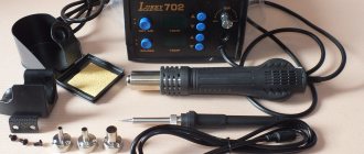
For example, you need to desolder a microcircuit from a board using a Lukey 702 soldering station.
Many radio amateurs and electronics engineers set heating parameters above 300 °C.
At the first moment, the part is exposed to about 200 °C. The contacts and the surrounding area of soldering work are at room temperature.
The heating of the part reaches 300 °C, but the contacts have not yet reached 200 °C.
The microcircuit experiences a critical temperature of 350 °C. Meanwhile, the surrounding soldering area is heated unevenly, even if the hair dryer is evenly moved across the soldering area. A noticeable temperature difference appears at the contacts of the part.
400 °C and the microcircuit begins to fry.
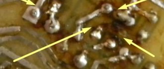
A little more, and it will unsolder due to the fact that the contacts have practically heated up until the solder melts. But this happens because the board has warmed up. And in this case, it happened unevenly. High temperatures lead to thermal breakdown of the microcircuit and it fails. The board bends, turns black, and bubbles appear due to boiled PCB and its components.
This soldering method is very dangerous and ineffective.
A simple DIY hair dryer
Everyone has long known about the purpose and technology of using a construction hair dryer, so we will not dwell on them. Stores offer a wide selection of such tools, but sometimes situations arise when you simply don’t have it at hand. It is in this case that some craftsmen are forced to resort to making homemade structures.
The general principles of operation and internal structure of a conventional hair dryer and its construction modification are the same. But that's where the similarities end.
The main reason is the difference in the temperature of the air that passes through the hair dryer. A regular model heats it up to 50-60 degrees Celsius. The construction device heats the air to 600-650 degrees.
The high operating temperature determines the use of heat-resistant materials for its manufacture.
To make a construction hairdryer with your own hands, you should abandon the idea of building it on the basis of a conventional model. All parts, including the body, will have to be redone.
The electrical connection diagram can be found on the Internet or copied by disassembling an old hair dryer.
The components you will need are nichrome wire, a small fan with a metal impeller, a piece of metal pipe and a power cord.
Work begins by making the working part from a piece of water pipe. Four or six triangular cuts are made at one end. The resulting petals are evenly bent inward, forming an air nozzle. The seams must be welded and carefully sanded.
Now we have to make the heating element. It should be slightly smaller than the diameter of the working pipe and not touch its walls. Heating spirals are made from nichrome wire by winding it around a thick nail.
The finished spiral needs to be wound on a ceramic or other heat-resistant base, for example, on mica plates, which can be borrowed from an old hair dryer. The closer the spiral turns are located to each other, the higher the air heating temperature will be. A switch and a power cord are soldered to the ends of the spiral.
The heating element is installed inside the working pipe, isolating it from the metal with asbestos or mica plates.
The working pipe with the heater is wrapped on the outside with sheet asbestos and attached to the handle with metal clamps. The homemade construction hairdryer is ready.
How to desolder a microcircuit
How do you solder parts without damage?
It is necessary to analyze the soldering area and equipment:
- Estimate the thickness of the board. The thicker the board, the more difficult and longer it takes to warm it up. The board consists of layers of tracks, masks, pads and many metal parts that are very heat-intensive.
- What's nearby? To avoid damaging surrounding components, they must be protected from temperature. The following will cope with this task: thermal tape, aluminum tape, radiators and coins.
- What is the ambient temperature ? If the air is cold, the board will have to be heated a little longer. Of particular importance is what is located under the board. No need to solder on a metal plate or on an empty bench. A wooden board or a set of napkins works best. And at the same time, the board must be in the same plane, without distortions.
- Equipment. Many soldering stations are sold without calibration. The difference between the temperature shown on the indicator and the actual temperature can reach either 10 °C or 50 °C.
How to solder a resistor to an LED
If your circuit does not provide for current limitation by the so-called driver, then you can use resistors the old fashioned way.
It is impossible to connect LEDs directly to the network, since in addition to the increased current, it is also variable. The resistor and driver convert the current to direct current.
Each LED ideally needs a separate resistor. This is if there are few diodes. If there are, for example, a hundred of them, as in some garlands, or even a couple of dozen, you will have to purchase a driver.
If you are encountering the concepts of “resistor” and “driver” for the first time, we have selected visual instructions:
The resistor must be connected in the circuit after the power supply and before the LED. It just solders. In the chapter “Features of soldering” we left a video on how to solder any contact (see above). There are no special features here. The only thing that can be doubted is the choice of flux, that is, a substance that cleans the contact surface from oxide and/or grease film. As an option - a special paste.
How to solder with a hairdryer correctly
It is necessary to cover all small components that are vulnerable to overheating with protection.
In this case, aluminum tape is used. It protects components well from temperature and holds the board components tightly. However, it adds heat capacity to the soldering area. Thermal tape also protects well, but sticks to the board less well.
The board is placed on a material that has the least heat capacity and slowly releases temperature to the environment. You can use, for example, a wooden plank. And at the same time, the soldering area should not be inclined.
It is best to apply flux to the contacts. It distributes heat well compared to heated air, but you should not add too much of it. It may boil, hiss, or interfere with soldering.
The first step is to warm up the soldering area. The hair dryer is set to about 100 °C and maximum air flow.
It is necessary to warm up both the part itself and the surrounding soldering area with contacts in a circular motion.
Next, after about a minute, you should gradually increase the heating.
The difference with the contacts will be small. Thus, within a few minutes, increase to 300 °C.
Steps of about 20 - 30 °C for every tens of seconds.
How to understand that a part is already soldered
A glare appears on the contacts. Using tweezers, gently push the chip. If it moves easily and smoothly from side to side, then it can already be removed; if not, we heat it further.
This technique must be individually adjusted for each soldering and soldering station. For example, sometimes you will have to heat the board longer, and sometimes about 240 °C will be enough. The soldering method depends on the case.
Compliance with safety regulations
When repairing any device that is powered from the mains, safety precautions must be observed. LED lighting devices, like incandescent light bulbs, are connected to a 220 volt network. Therefore, the master must be careful and take into account the recommendations:
- After turning off the lamp, you must manually discharge the capacitors. To do this, the terminals are short-circuited with a metal device with a dielectric handle.
- during the desoldering process, you must not leave the soldering station unattended, as this may cause a fire;
- When turning on the installed light bulb, it is better to turn away, as there is a possibility that due to possible mistakes it will explode.
Soldering LEDs is not an easy process for a beginner. Repairs should only be started if you have experience working with a soldering iron and are familiar with the design and operating principle of chips.
Alloy Rose
To reduce the risk of overheating, Rose alloy can be used. It will help reduce heat to 120 °C. In this way, you can remove the part from dangerous and sensitive areas. Just add a couple of solder granules and a little flux.
After tinning the contacts, the part is easily desoldered. You need to carefully desolder the contacts; they can easily be damaged due to sudden movement.
The resulting solder must be removed from the board. It is very fragile and not suitable for use.
Combined method
Another very effective technique. If during soldering the part is poorly soldered or does not desolder, this is a consequence of low-quality solder, flux, or insufficient heating of the board.
To do this, while working with a soldering iron, you need to help from above with a soldering hair dryer. The hair dryer should be set to 200°C. This way, heating will occur faster, and the temperature at the contacts will stabilize, and the surrounding air will absorb less heat.
In what cases will soldering with a hairdryer not work?
A soldering gun usually reaches a power of no more than 500 W. The lower the power, the less the board area can be heated.
A massive board requires bottom heating. Most often this is a stove that heats up to 100 - 200 °C. The printed circuit board will be heated evenly. And use a hair dryer to bring the solder to melt.
You can also use a hair dryer. It has a larger nozzle and its power can be up to 3000 watts. However, a hair dryer is not a solution either. Due to the fact that only the part and a small surrounding space around it are heated, after soldering the board is deformed due to the high heating difference, thereby tearing off the leads from the pads (this is especially true for large BGA parts).
The need to dismantle radio elements arises in several cases:
- Dismantling the faulty element;
- Incorrect installation of the radio component;
- Soldering from the donor board due to the lack of a new microcircuit.
In all these cases, except for the first, the main conditions are maintaining the integrity and working condition of the soldered part and the integrity of the printed circuit board.
To carry out this work, it is necessary to observe accuracy and simple rules that were developed back when most of the range of radio components was in short supply. The urgent question was how to remove an expensive microcircuit from the board without damaging it.
Making a contact soldering iron
This option can be considered the simplest and cheapest.
This design regulates the voltage on the soldering iron by changing the heating temperature of the tip. The performance of the heater and the position of the regulator are determined experimentally. The soldering process can be customized to suit your needs and specific production times. A dimmer for a chandelier can act as a voltage regulator. The only disadvantage of this idea is the small range of possible outlet temperatures. That is, for soldering it would be better to make the voltage range 200-220 V, and not 0-max. Most likely, you will need to modify the circuit, adding a “fine-tuning” resistor to the main resistor.
Assembly diagram at home
The rectifier bridge in this circuit will allow you to increase the voltage from 220 V at the input to 310 V at the output. This option is relevant for home craftsmen whose home has low electrical voltage, which does not allow the soldering iron to heat up to operating temperature. If you don't have a dimmer, you can do it yourself.
Chip types
The wide variety of microcircuit packages has led to the fact that soldering techniques began to differ. Previously, the most widespread were microcircuits with pin pins for mounting into holes on a printed circuit board. Subsequently, with an increase in the degree of integration and the widespread use of automated soldering lines, surface mount elements with flat or ball leads began to be used.
ICs (integrated circuits) with solder pins are typically DIP and SIP packages with two and one row of pins, respectively.
Surface mounting ( SMD ) allows installation of ICs with pins of the following types:
- Flat leads brought outside the housing - SOIC, SOP, QFP (square housing);
- Flat legs, bent inward, under the body - SOJ, PLCC, QFJ;
- Ball terminals - BGA.
Each variety has several subspecies. The total number of housing types is in the dozens.
Selecting soldering paste
The quality of any flux is expressed in the fact that during soldering it does not burn out, it only barely evaporates, and the products of its decomposition are easily removed with a solvent. The best flux is special pastes. We chose the top names based on the experience of familiar masters:
- Interflux 2005 and 8300
- Kingbo RMA-218
- Amtech RMA-223
- Rexant BGA and SMD flux gel
Just in case, keep in mind the old, “old-fashioned” ways of finding flux in a remote village. This is an aspirin tablet, fruit juice, olive oil, ammonia with glycerin, rosin with alcohol. The most obvious one for rural areas is pine or spruce resin. You need to melt the resin over low heat and then pour it into matchboxes.
Safe work with semiconductor radio components
Before you unsolder a part from the board with a soldering iron, you need to know the following. Semiconductor elements are extremely sensitive to overheating. Also, tracks on a printed circuit board at high temperatures or when the soldering time is exceeded can peel off from the substrate or break, which is even worse.
Temperature conditions
The temperature of the soldering iron tip should be 200-250⁰С. At higher temperatures, peeling of the printed tracks and overheating of the microcircuit may occur. The same goals are set for the soldering time of one leg - no more than 3 seconds.
Note! Some sites advise for dismantling to focus not on the temperature, but on the power of the soldering iron. It is not right. Their temperatures are the same, it’s just that a less powerful one may not be able to cope with melting the solder at the pin due to intense heat removal, and a too powerful one can easily overheat the pins and the board. The best option is a 40 W soldering iron.
Many microcircuits are sensitive to static electricity. It is necessary to work with an electrostatic wrist strap on and a grounded tool.
Board design
Printed circuit boards differ in the number of printed layers and the method of installing radio components:
- Single layer;
- Double layer;
- Multilayer;
- For DIP elements;
- For SMD components.
One board can contain both DIP and SMD elements on one or both sides. Multilayer printed circuit boards, in addition to outer layers, have internal ones, which usually serve for general shielding or wiring of power circuits. Thus, the motherboards of modern computers or mobile phones have up to seven layers.
Dismantling techniques
The method of soldering microcircuits depends mainly on the type of pins, although there are universal methods.
Dismantling the microcircuit with a soldering iron
This is the most time-consuming and unreliable method. It is used only when the number of microcircuit legs is minimal. Before soldering microcircuits with a soldering iron, the tip of the tip is carefully tinned and cleaned of solder residues so that it remains only in the form of a thin film. The molten solder that surrounds the IC leg is transferred to the tip under the action of tension. By repeating the procedure several times, the leads are completely released.
Important! Before each touch of the board, the tip is cleared of solder. The touch time should not be more than three seconds. If the leg is not completely freed, you can only work on it after some time has cooled down. At this time, you can make the following conclusions.
Removing the chip using a razor blade
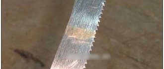
When working with planar elements, an ordinary razor blade will come to the rescue. For convenience, the razor blade is broken in half lengthwise. Leaning the blade close to the border of the terminal and the board, heat the scion until it melts. By inserting a blade between the leg and the board, they are separated. The blade is made of stainless steel, so solder does not stick to it.
Using dismantling braid
The special dismantling braid works thanks to the capillary effect, drawing in the molten material. You can use braided shielded cable with the same effect. The braid must be clean, without traces of oxidation. In order to improve the spreading of the melt, the braid is moistened with liquid flux.
Dismantling microcircuits using a desoldering pump
The desalination pump is a special piston that, when moving, draws in the melt, releasing the outlet. This method is suitable for working with DIP and SIP components.
Using medical needles
This method has proven to work best when dismantling ICs, especially for single-sided printed material. Double sided PCB can also be used to remove needles from syringes. When choosing a needle, you need to ensure that its inner diameter allows the leg of the microcircuit to fit freely, and its outer diameter allows it to fit into the hole on the printed circuit board. The tip of the needle is ground with a file until a smooth surface is obtained.
The needle is placed on the tip of the leg and the terminal is heated with a soldering iron. After the solder has melted, the needle is inserted into the hole of the board and smoothly rotated around the axis until the tin solidifies. After this, the needle is removed from the stem, which is now completely free. The needle material (stainless steel) is not tinned, so rotation around the stem is only necessary to make it easier to remove it from the hole.
Use of alloy rose
Using a rose alloy, you can desolder all the terminals of the IC at the same time, due to the fact that the low-melting alloy spreads between the terminals and evenly and simultaneously transfers heat to all of them from the heated soldering iron tip. After complete heating, the part is carefully removed from the board using tweezers.
This method has one disadvantage - after dismantling, it will not be possible to collect the remaining rose alloy, since it will be clogged with excess tin and lead, which will change its composition and melting point.
How to desolder a microcircuit from a board with a hairdryer
When working with SOJ, PLCC, QFJ and BGA packages, a soldering station or hair dryer with temperature control is required. Using the station, the entire section of the board is heated until the microcircuit is released, and using a hair dryer with a nozzle, a stream of hot air is directed to the terminals of the IC until they are released.
Radioelements must be desoldered at a temperature of 250⁰C. To prevent overheating, adjacent elements should be covered with aluminum foil.
How to remove capacitors from a motherboard
To desolder capacitors or other two-terminal elements, there is no need to use a special soldering tool. During the dismantling process, one of the terminals of the capacitor is heated, while simultaneously tilting the element so that the leg comes out of the hole. Next, repeat the same with the second leg, tilting the part in the opposite direction. To avoid tearing, do not press hard on the capacitor. By warming up both terminals in turn, they are gradually released.
From a soldering iron and a dropper
To make a soldered hair dryer with your own hands, you can use a simple soldering iron with the protective casing removed from it.
When taking it as the basis for a future heater, it is necessary to modify the design, which consists of the following:
- First, the tip is removed from the working part of the soldering iron, after which the mica tube with the nichrome winding placed underneath it is completely pulled out of the wooden handle-holder.
- Then the power wires suitable for the heating element are disconnected and also pulled out of the wooden holder, but from the other side.
- After this, a hole of the required size is drilled in the side of the handle, into which the previously disconnected network wire is threaded (towards the working part).
- At the next step of making a soldering gun, take a dropper, from which the tip is cut off in the area where the rubber skirt is located. Then the exposed part of the tube is inserted into the network hole of the wooden handle.
- Next, the rubberized seal (skirt) of the dropper is pressed with force against the end part of the holder, ensuring reliable sealing of the docking area.
- Upon completion of these actions, the ends of the drawn power wire are reconnected to the nichrome winding and reliably insulated.
- A piece of telescopic antenna of suitable diameter is inserted into the hole where the soldering iron tip was previously located and carefully clamped with a locking screw.
The tightness of the inlet hole in the handle will ensure effective inflation with cold air coming from the compressor station.
At the final stage of assembling the soldering gun, you should return the heating tube with the nichrome winding to its place, having previously wrapped it with several layers of aluminum foil.
Then the heater prepared in this way is recessed into a wooden handle and securely fixed using a flexible copper wire wound along the entire length of the protective coating.