The welder needs a set of tools and accessories and must be provided with personal protective equipment and special clothing.
Tools and accessories.
Welding tools include:
1) Electrode holder, on which labor productivity and safety depend. The electrode holder should be light (no more than 0.5 kg) and easy to handle.
2) A shield or mask is used to protect the welder’s eyes and facial skin from the harmful effects of infrared radiation and metal splashes.
3) Welding wires, through which the welding current flows from the welding machine to the place of work, brand PRG, APR, PRGD, KG, KOG, etc. with rubber insulation.
Welder accessories include:
— a steel brush used to clean metal from dirt, rust before welding and slag after welding;
— a hammer with a pointed end for beating slag from welds and for supplying a personal stamp;
- a chisel for cutting out defective areas of the weld.
To measure the geometric dimensions of the seams, the welder is given a set of templates or a universal welder template UShS (Figure 39).
The universal welder's template is designed to control weld preparation elements, electrodes and weld elements.
Designation: “Universal welder template UShS 3 model 00314 TU 3936-050-00221190-99.” Main technical characteristics of the template:
— range of measuring the depth of defects (dents, nicks), the depth of weld cutting to the root layer, the excess of edges (D scale), 0 - 15 mm;
— measurement range of the height of the seam reinforcement (scale G), 0 - 5 mm;
— measuring range of bluntness and seam width (scale E), 0 — 50 mm;
- gap measurement range (I scale), 0.5 - 4 mm;
— measuring range of edge bevel angles (scale D), 0 — 45 degrees;
— nominal values of the diameters of the electrodes measured by the template (grooves G): 1; 1.2; 2; 2.5; 3; 3.25; 4; 5 mm;
— weight (no more), 0.18 kg.
Device and principle of operation.
The template consists of a base 1 connected by an axis 4 to a slider 2 and fixed to the slider with a pointer 3 (Figure 39).
Figure 39 — Universal welder template UShS-3
Control is carried out as follows:
1. Control of the depth of the cavities, the depth of the nicks, the excess of the edges of the depth of the joint to the root layer and the height of the reinforcement of the seam is carried out by installing the template with surface A on the product, then by turning the slider 2 around axis 4, bring the pointer 3 into contact with the surface being measured. The result is read against the K risk on the G scale.
2. The gap is controlled by introducing the engine 2 with its wedge part into the controlled gap. The result is read using the I scale marked on the engine.
3. Check the bluntness of the seam and the width of the seam using the E scale, using it as a measuring ruler.
4. Control of the bevel angles of the edges is carried out when installing the template with surface B on the product generatrix. Then, by turning the slider 2, align its surface B with the surface being measured without a gap. The result is read on a scale D against the surface of the slider B.
5. Determination of wire diameters is carried out using grooves G. Purpose indicators. Name of the indicator. Unit of measurement. Meaning. Control of the depth of defects (dents, gouges), depth of seam cutting to the root layer, excess of edges (D scale), 0 - 15 mm. Control of the height of the seam reinforcement (scale D), 0 - 5 mm.
Control of the amount of blunting and width of the seam (scale E), 0 - 50 mm. Gap control (scale I), 0.5 - 4.0 mm. Control of bevel angles of edges (scale D), 0 - 45 degrees. Determination of the nominal value of the electrode diameter, 1.0; 1.2; 2.0; 2.5; 3.0; 3.25; 4.0; 5.0 mm.
The welder also uses some measuring tools (ruler, tape measure). A square is used to check angles.
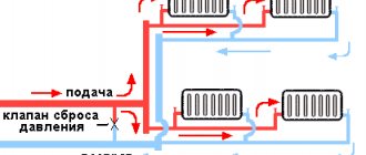
Sound-absorbing partitions and cabins
Sound-absorbing partitions and cabins are designed for organizing welding, stripping, etc. stations. and protect others from production noise, welding spatter, grinding sparks, etc.
Sound-absorbing partitions and cabins can be used to organize a single workplace, as well as to delimit the entire workshop into separate sections.
The range of noise-absorbing partitions is quite wide.
Simple noise-absorbing partitions make it easy to limit a temporary workplace or get a separate welder’s cabin, which is easy to assemble/disassemble and install in a new location.
Modular noise-absorbing partitions offered by industry today make it easy to get a separate welder’s cabin, increase the area of an existing cabin, or create a complex of cabins. All elements are easy to assemble/disassemble and install in a new location.
Electrode holders
The main working tool of a welder during manual welding is an electrode holder. It is designed for attaching the electrode and supplying welding current to it. Electrode holders are used for manual arc welding and gouging with all types of coated electrodes. They must withstand 8 - 10 thousand clamps, be light (weight no more than 0.5 kg), also ensure reliable fastening of the electrode in the position required for welding, have reliable electrical insulation, not heat up during operation, the time for replacing the electrode should be no more than 4 s.
There are two main types of electrode holders:
— screw-type electrode holders (Figure 40) consist of a convenient holder that prevents slipping in the hand, and an upper rotating part with which the electrode is securely held. The electrode is inserted into a special hole in the upper rotating part of the holder;
— electrode holders with a clamp (Figure 41) have a clamping part that also securely holds the electrode. The electrode is inserted into this clamp.
Figure 40 — Screw-type electrode holder
Figure 41 — Passat-type electrode holder
a - diagram; b - general view 1 - spring protective cap; 2 - spring; 3 — lever with upper jaw; 4 - thermal insulation; 5 - lower lip; 6 - cone of threaded bushing
Other excellent external electrode holders are modifications of the designs described above.
The symbol of an electrode holder according to GOST 14651 consists of the type of electrode holder, modification number of the electrode holder, type of climatic modification, category of placement according to GOST 15150-69 and the designation of this standard.
The modification number for the electrode holder is assigned by the All-Union Research, Design and Technological Institute of Electric Welding Equipment (VNII-ESO) of the Ministry of Electrical Industry.
An example of a symbol for an electrode holder for a rated welding current of 250 A, modification 17, type of climatic version U1 in accordance with GOST 15150-69: electrode holder ED-2517 U1 GOST 14651-78.
The design of electrode holders combines ease of use, durability and reliable fixation of electrodes of any diameter. The electrode holder options are designed for use when welding with currents up to 200 A and 300 A, respectively.
According to GOST 14651-78, electrode holders are produced in three types depending on the strength of the welding current: type 1 - for a current of 125 A; 2 types - 125 - 315 A; 3 types - 315 - 500 A.
In terms of electrical safety, electrode holders must comply with the requirements of GOST 12.2.007.8-75.
There are special electrode holders - for example, for flameless welding, for underwater welding (GOST 14651 does not apply to them).
Technical characteristics of some electrode holders are given in Table 5.
Table 5 - Technical characteristics of electrode holders
| Parameter | Electrode holder type | ||||||
| EP-2 | EP-3 | ED-125-1 | ED-300-1 | ED-500-1 | EU-300 | EU-500 | |
| Permissible welding current | 250 | 500 | 125 | 300 | 500 | 315 | 500 |
| Diameter of metal rod, mm | 6 — 8 | 1,6 — 3 | 2 — 6 | 4 — 10 | 3 — 6 | 5 — 8 | |
| Connected cable cross-section, mm2 | 50 | 70 | 25 | 50 | 70 | 50 | 70 |
Plasma welding equipment used
Equipment for welding work (for plasma processing) consists of the following elements:
- burners (plasmatron);
- power source (inverter);
- cylinder with plasma-forming gas;
- protective gas cylinder;
- water cooling systems;
- cable package.
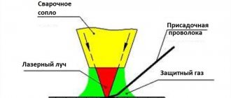
A welding torch is a complex device consisting of electrodes, pipelines for supplying gases and coolant, and an electrical cable for supplying power to the electrode.
The design of the torch is influenced by the power of the welding equipment. Low-power devices are equipped with burners with a retractable cathode, which, through a control button, is connected to the anode nozzle and excites the arc.
Manual plasma welding is performed using a gun-shaped torch that is comfortable to hold in your hands. Plasma-water welding is carried out by a combustion device in the form of a gun, which also has a discharge chamber and a steam-generating device.
More powerful equipment for welding work is equipped with torches with a fixed cathode. It consists of:
- cathode;
- cavities for working gas;
- cavities for shielding gas;
- anode (with a cavity for cooling);
- housings.
Torches for high-power welding equipment do not have handles, as they are attached directly to manipulators or machines.
The power source in the equipment is inverters, which have almost completely replaced transformer energy sources. Thanks to modern pulse converters based on IGBT transistors, a stable operating current is provided, which is adjustable to operate the equipment in various modes.
Welding cables, cable connectors and lugs
Welding cables.
To supply current to the electrode holder and the product from the power source, flexible welding cables of the RGD, RGDO, RGDV, KG, KOG, KPG, KSssh brands are used. The length of the flexible cable to which the electrode holder is connected is usually 2 - 3 m, the rest of it can be replaced with cables of the KRPGN, KRPNT and KRPSN brands. It is not recommended to use a cable longer than 30 - 40 m, as this causes a significant voltage drop in the welding circuit, which negatively affects the quality of welding. The cable connecting the workpiece to be welded to the power source can be more rigid and less expensive, for example PRN. The cross-section of welding cables is selected depending on the arc current and permissible loads for a specific cable brand.
The welding cable KSssh (Figure 42) is intended for connection during arc welding of electric holders, automatic and semi-automatic welding installations with a power source for rated alternating voltage up to 220 V, rated frequency 50 Hz or constant rated voltage 700 V.
Construction: copper conductor, stranded, class 5 for conductors with a cross-section from 10.0 to 95.0 mm2 and class 4 for conductors with a cross-section of 120.0 mm2 according to GOST 22483-77; insulation: the first layer, consisting of cross-linked polyethylene, is applied by crimping, giving the cable a round shape, the second layer is made of polyvinyl chloride plastic.
Figure 42 — General view of the welding cable KSssh
Number of cores: 1.
Section: 10.0; 16.0; 25.0; 35.0; 50.0; 70.0; 95.0; 120.0 mm2.
Welding cable KG is a single-core flexible insulated wire woven from a large number of copper, annealed and tinned wires with a diameter of 0.18 - 0.2 mm. The supplied welding cable complies with TU 16 K73.05-93. Designation: KG (KOG) 1 25 - flexible cable (extra flexible), 1 - one core in the cable, numbers after the multiplication sign - cross-section of the cable core. KGN cable - with zero core.
Construction: copper conductor, stranded, round, class 5 according to GOST 22483. The conductors of cables intended for operation in areas with tropical climates are made of tinned copper wire or coated with tin-lead solder with a tin content of at least 40%.
The separating layer is a synthetic film; it is possible to apply insulation without film if there is no rubber sticking.
Insulation - made of insulating rubber. Insulated cores have a distinctive color, solid or in the form of a longitudinal stripe. The insulation of the neutral core is blue; if there is no neutral conductor, blue color is used to color any conductor except the grounding conductor. The grounding conductor has a green-yellow color or is designated by the number 0. The colors of single-core and two-core cables are not standardized. The colors red, grey, white and, unless combined, green and yellow are not used for coloring the cores of multi-core cables.
Stranding - insulated cores are twisted with a twist pitch of no more than 16 twist diameters.
The separating layer - on top of the twisted cores - is a synthetic film or talc, or other similar material. Production without film is allowed, provided that the insulated cores are separated from the sheath.
The shell is made of hose rubber. The sheath of cables intended for use in areas with cold climates is made of cold-resistant hose rubber. The sheath of cables intended for use in tropical conditions is made of antiseptic rubber. In single-core cables of the KG brand, it is possible to replace the insulation and sheath with an insulating protective sheath. The nominal thickness of the insulating protective sheath is equal to the sum of the nominal thicknesses of the insulation and sheath or twice the thickness of the insulation.
The KG welding cable is designed for connecting mobile mechanisms to electrical networks at an alternating voltage of 660 V with a frequency of up to 400 Hz or a direct voltage of 1000 V, with bends with a radius of at least 8 cable diameters at an acceptable heating temperature of the current-carrying conductors up to plus 75 °C.
For tropical cables, the letter “T” is added to the cable grade, separated by a hyphen. For cold-resistant cables, the letters “ХЛ” are added to the cable grade through a hyphen. In the symbol for cables with a zero core, the letter “n” is added to the brand; for cables with two and three main cores and one or two auxiliary cores, the letter “c” is added.
The characteristics of the KG cable, intended for connecting the electrode holder and grounding clamp to the welding current source, are presented in Table 6.
How to choose a welding cable?
The welding cable is selected depending on the welding parameters.
When making preliminary calculations, it is necessary to assume that the current density in the cable at the rated value of the welding current of this power source should not exceed 5 A/mm.
For example, for a rated welding current of 250 A, the cross-section of the welding cable S is 50 mm, and the total resistance R of the forward and return wires should be no more than 2:250 = 0.008 Ohm. The total length L of the forward and return wires permissible for a given cross-section is determined from the simple formula R = pl/S. For a cable with copper conductors (p = 0.017 L0″6 Ohm) it will be about 24 m, i.e. the length of both the forward and return wires is 12 m. More precise parameters for the operation of the cables must be taken from the passport data. Table 6 — Welding cable KG
| Name | Current load, no more, A | Cable weight, kg/m |
| Welding cable KG 1 16 | 175 | 0,31 |
| Welding cable KG-HL 1 16 | ||
| Welding cable KG 1 25 | 220 | 0,45 |
| Welding cable KG-HL 1 25 | ||
| Welding cable KG 1 35 | 270 | 0,59 |
| Welding cable KG-HL 1 35 | ||
| Welding cable KG 1 50 | 330 | 0,82 |
| Welding cable KG-HL 1 50 | ||
| Welding cable KG 1 70 | 400 | 1,09 |
| Welding cable KG-HL 1 70 | ||
| Welding cable KG 1 95 | 465 | 1,4 |
| Welding cable KG-HL 1 95 | ||
| Note: HL - in cold-resistant version | ||
It is advisable to select the cross-sectional area of the welding cable and its length in such a way that the voltage drop in the connecting wires (forward and return) of the welding circuit does not exceed 2 V. In this case, the voltage drop is defined as the difference in voltage measured at the terminals of the welding circuit of the power source (transformer, rectifier , unit) and between the electrode and the product.
Electric welder's workplace
The productivity of an electric welder and the improvement of welding quality depend on the conditions in which welding work is carried out, i.e., on the correct organization of the welder’s workplace (welding station). The welder's workplace can be located directly next to the product being welded (large sizes) or in a special cabin. Directly near the product being welded, as a rule, a mobile workplace (welding station) is organized, fenced with portable work shields. Special booths are installed at permanent locations when welding small-sized products. Portable work panels and cabins serve to protect all workers from electric arc radiation.
The cabin for one welder has dimensions of 2 x 2 or 2 x 2.5 m and a height of at least 2 m. To improve ventilation in the cabin, the walls are not brought up to the floor by 200...250 mm. The frame of the cabin is metal, and the walls are made of fire-resistant material, and sometimes plywood. The cabin doorway is covered with a canvas curtain suspended on rings. The floor in the cabin is made of fire-resistant material: brick, concrete, etc. The cabins are painted in light colors.
The following equipment is installed in the cabin: power supply (in the absence of centralized current distribution); metal welder's work table; welder's chair with lifting screw seat; box for electrodes; tool box; racks for parts and finished products; electric furnace for calcining electrodes (in the absence of an electrode workshop); network closed switch. When power sources are from a direct current generator, as well as when powering posts from a multi-station machine or several parallel-connected generators, it is advisable to install the power sources outside the cabins, in a special room.
The effectiveness of local suction of harmful impurities that are released during the welding process from the welder’s breathing zone largely depends on the maximum proximity of the exhaust intakes to the place of arc burning. From this point of view, the best welding work tables are tables with gas and dust exhaust to the side or down. We can recommend welding tables models S10020 and S10040 (Fig. 1.2). The products to be welded are placed on tables for manual and mechanized welding. The use of tables significantly improves the working conditions of the welder. In the design of the welder's table mod. S10020 is equipped with a supply and exhaust device that simultaneously ensures the effective removal of harmful substances and the supply of clean air to the welder’s breathing zone.
The characteristics of serially produced fixed welding tables are given in Table. 1.11.
Return terminals (ground terminals)
When connecting the power source to the welding circuit, you should pay attention to the quality of the electrical contacts at the output terminals of the device and at the points where the product and electrode are connected.
The return wire, i.e. the wire connecting the product or fixture being welded to the power source, may be less flexible and is usually made from cheaper wire of the PRG, PRN brand (GOST 1977-68). The return wire is often equipped with a quick-release clamp (terminal) of electrically conductive metal for connection to the work being welded.
Wire clamps can be spring type (Figure 43) or screw type with notches for reliable electrical contact even in cases where the metal is not completely clean. It is advisable to provide the possibility of supplying current through both jaws of the clamp. Often, when working in stationary conditions, the return wire is replaced with a copper, aluminum or steel busbar. The cross-section of a steel busbar should be increased compared to copper, since the resistivity of steel is much greater. In addition, when welding with alternating current, additional losses associated with the surface effect are taken into account, i.e., with the phenomenon of uneven current density in conductors (an increase in current density at the periphery and a decrease inside the conductor).
Figure 43 - Spring type clamps
The clamps provide excellent contact with the product, are reliable and durable, and are designed for use in welding with currents up to 150 - 200 and 300 - 400 A.
Clamp terminals (Figure 44) and magnetic terminals (Figure 45) are also produced.
Figure 44 — Clamp terminal
Figure 45 — Magnetic terminal
Welding wire connectors. Special connectors are used to connect welding wires (cables). An example is the one-piece cable connectors SKN-25 (250A), SKN-31 (315A) and SKN-50 (500 A) with a screw connection with rare cable disconnection. Manufactured in climatic version U placement category 1 according to GOST 15150 (Figure 46).
Detachable connectors of the SKR type (Figure 47) require frequent disconnection.
One-piece cable connectors SKNP and detachable panel connectors SKRP (Figure 48) can be mounted on a rigid base.
Figure 46 — One-piece cable connector SKN
Figure 47 — Detachable cable connector type SKR
Figure 48 — SKNP one-piece panel cable connector (a) and SKRP detachable panel cable connector (b)
Necessary equipment for laser metal welding
Laser welding equipment has different dimensions and power, but all of it operates on a solid or gaseous working fluid. The difference lies in the way the light emission occurs. Metal processing on any type of machine is performed in the same way.
- Solid state installations.
The devices are used in continuous radiation mode. They are characterized by higher operating frequencies, as well as limited efficiency and power. Solid-state equipment is used when working with small-sized and thin-walled products.
- Gas apparatus.
If it is necessary to weld thicker workpieces, equipment with a gaseous working fluid is required. Excitation of radiation in a gaseous medium occurs due to an electrical discharge. This equipment is suitable for working with workpieces up to 20 mm thick. With this technology, the beam power increases and the efficiency also increases. Equipment for welding work has a complex device with a fragile glass bulb.
- Hybrid installations.
Parts with complex configurations and thick sheet metals are processed using hybrid welding systems. In addition to the laser head, they have a semi-automatic electric arc burner.
The filler material is a wire that fills the welding gap and forms the weld.
Welder clothing
Welder clothing is made from various fabrics if the basic requirements are met:
— fire resistance and heat resistance of the outer surface;
— the inner surface must be moisture-absorbing. The industry offers various clothing options,
for example, the ZEUS costume shown in Figure 49.
Figure 49 — “ZEUS” suit for men
Produced in accordance with TU 8572-111-54927561-2007.
Upper fabric:
— “Hercules” (Klopman International), cotton — 100%, density — 460 g/m, color green, NMVO impregnation “Hydrofoil”, KShchS-50, fire-resistant technology “Proban” (105-0019-03);
— “Arsenal”, cotton — 100%, 500 g/m, black color, MVO, fire-resistant finish (105-0019-79).
The welder also uses balaclavas (Figure 50), special shoes (Figure 51), and mittens (gloves, Figure 52).
Figure 50 — Welder’s balaclava “ZEUS”
The balaclava is manufactured according to GOST 17-635-87; TU 8579-00454927561-2007, “Hercules” and “Arsenal” fabrics are used, button closure; The balaclava has depth adjustment.
Figure 51 — Boots “Welder”
Special shoes for welders use nitrile rubber (nitrile) soles. This sole can withstand a wide temperature range from minus 40 to plus 300 °C, practically does not slip, has excellent wear resistance and good oil, gasoline, acid (up to 60%) and alkali resistance. These shoes are EN ISO 20345 HRO (Heat Resistant Outsole) certified and the outsole can withstand high temperatures. There is a mechanism for quickly resetting the shoes in the event of sparks or splashes of hot metal getting inside the shoe.
Figure 52 — ANSELL Workguard gloves
ANSELL Workguard gloves comply with GOST 12.4.01075, EN388, EN407, EN420. Leather gloves with a reinforced palm are excellent for welding work and are resistant to abrasion and tearing. All seams are stitched with Kevlar Fiber thread, the lining material is cotton. Length 380 mm. Special leggings are also used (Figure 53).
Figure 53 — Five-fingered split leather leggings
Gaiters are recommended for workers in the metallurgical industry and welders. Protect hands from sparks, splashes of hot metal, and elevated temperatures. Distinctive characteristics: cotton lining. Complies with GOST 17-528-85.
Edge preparation
Do-it-yourself metal welding begins with proper preparation of the edges of the products being joined. It is impossible to reliably connect two parts simply by placing one of them next to the other and welding it. In this case, we cannot talk about the reliability of the connection. The edges are shaped after preliminary cleaning.
According to their configuration, the cut edges will look like different letters, so a novice welder will easily remember them. After cutting the edges, begin to securely fix the components to be welded relative to each other. The best way to fix is to use tacks. If the parts are small, they can be inserted into a clamp and secured with clamping bars.