In electrical installation work, one of the most important stages in the work is connecting the equipment. The successful operation of the entire complex of electrical installations at the enterprise depends on the correct execution of all operations at this stage. Before connection, power lines and cables, control circuit wires (secondary switching circuits) are laid. These circuits connect various elements of equipment with a control panel and a protection system. After installation is completed, individual wires and cables are tested before connection. In this article we will tell you why you need to test wires and cables and look at the main methods.
Basic dialing methods
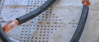
Detection methods depend on the cable brand and location conditions; with colored insulation of the cores, there are no problems. The cable is connected to the equipment according to the color of the cores on both sides. The difficulty arises when the insulation of all or several cores in the cable is the same color, and the cables are not marked. It is in such cases that a test is carried out, the ends on both sides of the cable are determined to belong to the same core, their integrity is determined, and markings are made.
Basic methods and equipment:
- Continuity tester can be performed by one person within one distribution cabinet and at distances of up to 100m;
- A digital multimeter, used in similar conditions, the device is set to continuity or resistance measurement mode.
- A homemade device with a lamp and batteries;
- Telephone handsets with batteries in the circuit.
- A step-down transformer complete with indicator or measuring instruments.
Purpose
Testing wires and cables is necessary in order to find the ends of one core.
For your information . The importance of dialing is best demonstrated by example. If a secondary circuit cable is laid, characterized by the presence of 12 cores, each with its own functionality, then a mistake cannot be made. A mistake can lead to the failure of an expensive device, as well as its failure to perform its functions.
Core integrity is important
Wiring continuity tester
Historically, at the initial stage of development of electrical engineering, a tester was called a pointer combined device, which includes:
- Voltmeter;
- Ammeter;
- Ohmmeter.
Then other options were added to modern devices, an electronic thermometer, light and sound indication elements, and controls and application methods were improved. As a result, instead of the old dial tester, it was replaced by its modern analogue, a digital multimeter with a liquid crystal display for displaying readings. One of the functions of the tester is wire continuity testing (checking the integrity of the wire).
Pointer combined device Ts 4342-M1. In order to ring a wire with a pointer tester, you need to carefully study the capabilities of the device, how to connect the measuring probes and in what position to put the switches on the control panel.
Familiarize yourself with the discrete division of the scale; the controls and scales are different on devices of different models. Let's consider the wire testing technique using the example of a pointer tester Ts 4342-M1:
- Set the batch switch of measurement modes to the 1 kOhm position, some models have Ohm.
- Turn on the fuse button, protecting the calibrated elements of the device circuit from incorrect connection. If in continuity mode the circuits are energized.
- Press the forward and reverse current measurement mode buttons, two black buttons at the bottom of the control panel;
- Connect the probe wires to the center and right terminals to measure resistance;
- To check the functionality of the device, connect the probes to each other, the arrow on the scale should move from left to right until it stops. Measurements are carried out on a scale marked kOhm, second from the top. If the arrow moves to the right towards zero, the device is working.
The advantages of this tester are reliable protection and measurement accuracy, but in case of continuity, it works as an indicator device. Accurate readings are not required here; the following can be considered disadvantages:
- the difficulty of setting the controls to the desired mode;
- large dimensions;
- Large measurement error when batteries are discharged; supply voltage should be within 3.5 - 4.5 V.
Determining the reason for lack of access to the Internet
In a pop-up window on the computer monitor, the message “Network cable is not connected” appeared, the LED on the network card did not light up.
You insert and remove the RJ-45 plug in the hope of poor contact in the connection and realize that the cable is faulty. If you do not have a separate network card installed in your computer, and the network cable plug is inserted directly into the motherboard, the LED will not light if the connection is disabled by software. Nowadays, a twisted pair network cable is often first connected to the router, which sometimes freezes. Therefore, first of all, you need to reboot the router. To do this, just disconnect it from the power supply for a minute and then turn it on again. It is quite possible that access to the Internet will be restored after this.
A shutdown can occur without your direct participation, for example due to unstable network voltage, running unlicensed programs or a virus. To check in Win XP you need to go to: Start / Settings / Control Panel / Network Connections and make sure that the connection is connected. Less often, but it also happens, the network card driver does not work correctly. You can check: Start / Settings / Control Panel / System / Hardware / Device Manager / Network Cards. There should be no warning signs.
Network cards very rarely fail; this sometimes happens after a severe thunderstorm. You can check the functionality of the network card by connecting it to a known-good line or installing it in another computer, not forgetting to install the driver for it. Sometimes it is possible to get a network card to work by moving it to an adjacent slot on the motherboard.
A call to the provider's technical service will help check the functionality of the line on their part. If everything is in order with the computer and the provider, it means that the twisted pair cable has failed and requires repair. You can, of course, call specialists and wait, but if you wish, it is possible to diagnose and repair the twisted pair cable yourself.
The following malfunctions of a twisted pair cable are most likely: - complete break of one or more wires - occurs frequently; - a short circuit between the conductors of one twisted pair or between the wires of adjacent pairs - is less common.
Checking the integrity of the wire in a coiled cable
To test wires in short cords or a coiled cable, just strip the insulation on the wires at both ends and start measuring:
- Connect the probe to a wire of a certain color, the second probe is connected to a similar wire at the other end. If the arrow deviates to the zero position of the scale, the wire is in good condition.
Testing a cable with colored wires, schematic connection of probes to single-color wires at different ends of the cable. A – cable insulation. B – Individual cable cores with colored insulation.
- With single-color wires or a laid out cable, where the distance does not allow the tester to work with different ends at the same time, all wires at one end are shorted together.
- On the other side of the cable, connect the probe to one wire and call all the other wires through it, in turn 1,2,3....
Testing a cable with wires of the same color
The disadvantage of this method is that it is not possible to isolate each core individually and label it. This must be done when the cable is rolled up in one place or using a transformer.
Process description
Cable or wire testing is the process of checking the integrity of an electrical conductor. During this process, the absence of cable/wire breaks and short circuits is checked.
Carrying out the appropriate procedure allows you to determine the location of the breakdown in the network.
Network performance should be measured correctly
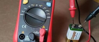
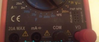
Testing wires with a multimeter
GE 2524 multimeter in the continuity position
The probe with the black wire is inserted into the connector with the ground symbol (housing), red above, into the connector for measuring resistance with the Ohm symbol “ Ω”. The disadvantage of many digital multimeters in dial mode is the delay in the sound indicator signal when touching the contacts. It is necessary to fix the probes on the wire for 2-3 seconds to make sure there is contact. This inertia in operation creates some difficulties in checking the integrity of the wire.
Multimeters of the UNI-T type have good performance in dialing mode; the sound indicator operates almost instantly when the contacts are closed.
Comparison table of characteristics of Fluke-179 and UNI-T UN61 multimeters
Please note that for all instruments it is advisable to use probes with gold-plated rods. Unlike steel ones, they are not subject to oxidation and provide reliable electrical contact.
Checking the electric heating element
You can also ring an electric water heating element with a multimeter. To do this, the probes of the device must be attached to the contact plates of the heating element. If the resistance reading is small, then the heating element is working. With very large values or one (depending on the model), the heating element is damaged and requires replacement.
Note! Sometimes one housing may contain two heating elements connected to voltage in parallel. In this case, you need to ring them separately, having first removed the jumper between them
It is very important for boilers and other water heating devices to ring the contacts of the heating element for penetration into the body
To do this, the probe is connected to one of the contacts, and the second - to the body of the heating device
It is very important for boilers and other water heating devices to ring the contacts of the heating element for penetration into the body. To do this, the probe is connected to one of the contacts, and the second to the body of the heating device. If the tester shows a certain value, the internal insulation has been damaged in this heating element.
To prevent electric shock, the heating element must be replaced.
If the tester shows a certain value, the internal insulation has been damaged in this heating element. To prevent electric shock, the heating element must be replaced.
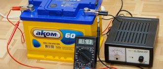
Continuity using a transformer
This method is effective for testing unrolled laid cables with wires of the same color. In this case, step-down transformers are used with different voltages at the taps of the secondary winding.
- The primary winding of the transformer is connected to a 220V AC source;
- The beginning of the secondary winding to the ground loop, to which the cable shield is closed;
- The remaining secondary winding taps with different voltages to the ends of the wires;
- On the other side of the cable, a multimeter is used to measure the corresponding voltage between the ground loop and the cable wires. Thus, the integrity of the core is checked and marked.
Diagram for connecting the cable to the transformer for dialing.
The multimeter is set to AC voltage measurement mode. It is recommended to use devices from Western manufacturers, since in this case the measurement mode is used, not the indication mode. Chinese S-99 type multimeters are very poorly calibrated; inaccurate voltage measurements can lead to errors when marking the cable. Therefore, for tapping a cable using a transformer, where voltage measurements are made, it is better to use a pointer device of the Ts-4342-M1 type.
Characteristics of the combined device Ts 4342 M1:
| Accuracy class | 2,5/4,0 |
| measurement ranges | |
| DC current in mA | 0,05 — 2500 |
| AC current in mA | 0,25 — 2500 |
| Voltage, DC | 0,1 — 1000 |
| Variable voltage in volts | 1,0 — 1000 |
| DC resistance in kOhm | 0,3 — 10000 |
| signal level when measuring voltage in dB(-) | -10 to+15 |
| frequency range in Hz | 45 — 2000 |
| Power supply | autonomous |
| Dimensions in mm | 215*115*90 |
| Weight in kg | 0,9 |
| operating temperature | from -10 to +40°С |
In most cases, all multimeters have a classic layout of controls with minor differences.
When taking measurements, you need to carefully look at the inscriptions with symbols. Summary table of main parameters for different models of multimeters:
| Model | LCD screen | U— | V~ | I— | I~ | R | The dial is connected. | Diode testing | Transistor testing |
| M830B | 7 segments 3.5 digits | 0.1mV - 1000V | 0.1V - 700V | 0.1mA- 10A | — | 0.1W-2mW | — | * | * |
| M830 | 7 segments 3.5 digits | 0.1mV - 1000V | 0.1V - 700V | 0.1mA- 10A | — | 0.1mW - 2mW | * | * | * |
| M832 | 7 segments 3.5 digits | 0.1mV - 1000V | 0.1V - 700V | 1mA- 10A | — | 0.1W-2mW | * | * | * |
| M838 | 7 segments 3.5 digits | 0.1mV - 1000V | 0.1V - 700V | 1mA- 10A | — | 0.1W-2mW | * | * | * |
To set the multimeter to the AC voltage measurement mode, you need to set the batch switch for changing modes in the sector with the “ V ~” icon to the maximum value within which measurements are taken. In our case, this will be any measurement limit greater than 20V; the wires from the probes are installed in the same connectors as when measuring resistance.
Cable TV Test Kits
There are also kits designed to work with coaxial cables. These include the Greenlee 402K and Hobbes TETP-900. Although, in principle, any of the sets described above can be used for these purposes.
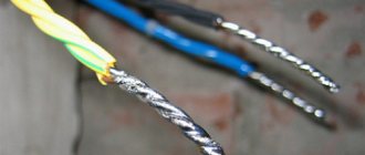
Making calls using handsets
The advantage of this method is that it is convenient to ring unrolled cables with wires of the same color. At the same time, electricians can communicate with each other. The disadvantage is that one person cannot do the work this way.
You will need two handsets and one battery, 4.5 volts is enough.
- Connect a 4.5 V battery into the microphone wire coming out of the handset. (Polarity does not matter). The main thing is that the current is constant and stable, without ripples, if not a battery is used, but a rectifier from an industrial network.
Connecting the power source to the handset, please note that polarity does not matter, the main thing is that the battery is connected to the circuit in front of the microphone.
- Connect the end of the wire connected to the capsule to the shielding sheath of the cable, the second to one of the cores;
- On the other side of the cable, the second tube is connected with one wire to the shielding sheath. The second wire is connected to different wires in turn until the installer at the other end of the cable responds.
Connecting tubes to a cable for wire testing; the positive wire can be connected to the shielding sheath on the cable or to the metal pipe in which it is laid. But it must be taken into account that the pipe must be solid or have electrical contact with a common ground loop for both sides of the cable.
Tip #1. To make the design easier, use a microphone headset from cell phones; in some cases this is very convenient.
Diagram for connecting micro headphones to a handset instead of a telephone capsule.
Independent dialing
It is best to ring the telephone cable using the handset of the device. This method is characterized by simplicity and mobility.
- An assistant is invited.
- The common core is determined. She can be anyone. Others are called in relation to the selected core. The selected one must be ringing initially.
- The first clamp of the main tube is connected to the main core. The second - to the other.
- The first clamp of the auxiliary tube is connected to the main core on the opposite side of the cable.
- The second switches alternately over the others. You need to find the one to which the assistant connected.
- When connected to the desired core, a crackling sound will be heard, indicating the occurrence of a closed circuit.
- A method for marking the detected core is discussed with an assistant. Pre-prepared tags are placed on the ringed type of core on both sides.
- The process is repeated for each subsequent wire.
- If there is no break, the conductors are inserted into the terminal block.
You can also ring your phone
Testing the cable with an indicator device with a light bulb
To do this you will need any power supply, a 1.5 battery; 4.5 or 9 Volts, wires with alligator clips and a lamp for the appropriate voltage.
Assembly of the circuit and procedure for use:
- Wires are soldered to the battery terminals;
- In the break of one of the wires, the polarity does not matter, connect an LED or a lamp;
- The dialing process is carried out using the same method as with a tester or multimeter. In this case, if the conductor is intact, instead of the arrow deflecting or the reading on the liquid crystal display, the light will light.
Such an indicator device allows you to test cables over distances of several hundred meters, depending on the state of charge of the battery.
Connection diagram for an indicator device with a light bulb for cable testing.
Tip No. 2 During installation work, when the lamps are constantly moving, it is recommended to use an LED. It is less susceptible to mechanical stress than a conventional incandescent lamp with a spiral and a glass bulb.
Finding the break point
After a break in the electrical wiring has been discovered, it is necessary to localize the place where it happened. For dialing in this case, you can use a tone generator, for example, the Cable Tracker MS6812R or TGP 42. Such devices allow you to determine the location of the break with centimeter accuracy, as well as determine the route of hidden wiring; in addition, the devices have other useful functions.
Model MS6812R
Devices of this type include an audio signal generator and a sensor attached to an earphone or speaker. When the sensor approaches the place where the UTP cable pairs or electrical wiring wires are broken, the tone of the sound signal changes. When a tone test is performed, the wiring must be de-energized before connecting the sound generator, otherwise the device will be damaged.
Note that with the help of this device you can test both power and low-current cables, for example, check the integrity of twisted pair cables, radio wiring or communication lines. Unfortunately, such devices will not allow you to determine the correct connection; special equipment is used for this purpose - cable testers.
The most common mistakes made when testing cables
- Incorrect setting of measurement modes or connection of probes to the sockets of the multimeter or tester. On old pointer testers, the operating mode switch is set to the 1 kOhm position, on modern devices in the dialing mode, with a diode or buzzer sign;
- When testing wires using a step-down transformer, use a pointer tester to check the power source. The voltage should be from 3.5 to 4.5 volts, otherwise the voltage will be measured with a large error;
- Before testing, thoroughly clean the contacts on the cable wires and test leads. Gold-plated contacts do not need to be cleaned; you can wipe them with cotton wool and industrial alcohol.
- When using pointer instruments, do not confuse the scale when measuring; it should be for alternating voltage with the sign “V~”.
- When testing wires in the distribution cabinet harnesses, the contacts on both sides must be disconnected from all elements of the equipment.
- Technical characteristics of PRKA wire
Program for checking access to the Internet Network Traffic Monitor
Search engines often search for the answer to the question: “a program for testing twisted pair cables.” A computer with Windows installed already has a program that displays the message “The network cable is not connected” if the twisted pairs in the cable are broken or shorted. You will have to look for the location of the break or short circuit yourself; there is no program that would indicate the exact location and cause of the malfunction. There are special testers for this, for example MicroScanner Pro.
It’s another matter if there is a connection to the Internet, but it is unstable or the download speed has suddenly dropped. To monitor network traffic, there is an excellent free program, or rather a utility called Network Traffic Monitor.
It allows you to measure data transfer speed in real time, observe changes in speed over time, save data on a hard drive, rubber windows, extensive customization options and many other useful services. Supports many languages, including Russian.
Installing the program on your computer is simple, just run the EXE file and press the confirm button several times. Network will automatically be added to startup and will monitor and save all data. To display any of the windows on the monitor screen, just right-click on the tray icon and select the desired window. Network Traffic Monitor is the best utility for analyzing and diagnosing network quality that I came across during my search. I have tested the functionality of the Network Traffic Monitor program with Windows HP and Windows 7. You can use the Network Traffic Monitor program with one click of the mouse from my website.
If the circuit breakers do not work
In this case, all electrical equipment and devices that are powered from this line are checked.
For example, if the lighting in a room stops working or 2 sockets on the wall do not work at the same time, then check the following nodes one by one:
- Turn off the power supply to the house network completely.
- Before checking the resistance, check whether the multimeter is working. This is done by short-circuiting the probes. The display should show “0”. If the readings are slightly different, for example, 0.1, this will indicate that the device has an error.
- Check the serviceability of the light bulb by unscrewing it from the socket. One probe touches the cartridge, and the other touches the end part. A buzzer and meter readings other than “0” and “1” indicate that the device is working.
- Check the wall switch by removing the panel, removing the screws, and removing it from the box. If there are no visible violations, then check the switch with a tester, installing probes on its contacts. The absence of a buzzer indicates that the switch is faulty and needs to be replaced. As a rule, after this the light appears in the room.
Test kits for security and fire alarm networks
There is only one such test kit in the SvyazKomplekt assortment - Greenlee 620K. In addition to the pair selection mode at the remote end of the cable, it also has specific functions:
- testing a normally open contact;
- testing a normally closed contact.
This will simplify the work of installing and checking the operation of any security, fire and other alarm systems.