We recommend purchasing:
Installations for automatic welding of longitudinal seams of shells - in stock!
High performance, convenience, ease of operation and reliability in operation.
Welding screens and protective curtains are in stock!
Radiation protection when welding and cutting. Big choice. Delivery throughout Russia!
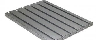
Slot milling
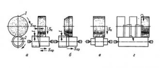
A recess of metal in a part, limited by shaped or flat surfaces, is called a groove. Grooves can be rectangular, T-shaped, dovetail, shaped, through, open, closed, etc. Processing grooves is a common operation on milling machines of various types and is carried out with disk, end and shaped cutters (Fig. 5.23).
Through rectangular grooves are most often milled with three-sided disk cutters (Fig. 5.23, a), disk groove or end mills (Fig. 5.23, b). When milling precise slots, the width of the disk cutter (diameter of the end mill) must be less than the width of the slot, and milling to a given size is carried out in several passes. Machining grooves with end mills requires the correct choice of the direction of rotation of the machine spindle relative to the helical grooves of the cutters. It should be mutually opposite.
Milling of closed grooves is carried out on vertical milling machines using end mills (Fig. 5.23, d). The diameter of the cutters should be 1...2 mm less than the width of the groove. Plunging to a given cutting depth is carried out by moving the table with the workpiece in the longitudinal and vertical directions, then the longitudinal movement of the table feed is turned on and the groove is milled to the required length, followed by finishing passes along the sides of the groove.
Curvilinear grooves are milled to their full depth in one working stroke. According to this condition, the resulting feed motion is assigned, equal to the sum of the vectors of the transverse and longitudinal feed motion. To reduce infeeding in places where the directions of the grooves change, it is necessary to process with cutters with minimal overhangs and reduce feed rates.
Milling of grooves of special profiles - T-shaped, dovetail-type - is carried out on vertical or longitudinal milling machines in three (T-shaped grooves) or two (dovetail-type grooves) transitions. Taking into account the unfavorable operating conditions of T-shaped and single-angle cutters used in these operations, the feed per tooth S should not exceed 0.03 mm/tooth; cutting speed - 20...25 m/min.
6 Key and milling units for processing shafts
If the grooves must have the most precise width, they should be processed on special keying machines. They work with a keyed two-tooth cutting tool, and the feed on such units is carried out according to a pendulum scheme.
Key-milling machine equipment ensures processing of the groove along its entire length when cutting the working tool to a depth of 0.2 to 0.4 millimeters. Moreover, milling is carried out twice (plunging and feeding in one direction, then the same operations in the opposite direction).
The described machines are optimal for mass and serial production of key shafts. They operate in automatic mode - after processing the product, the feed of the headstock in the longitudinal direction is automatically turned off and the spindle unit moves to the initial position.
In addition, these units guarantee high accuracy of the resulting groove, and the cutter wears out almost completely along the periphery, since milling is carried out with its end parts. The disadvantage of using this technology is its duration. Standard machining of grooves in two or one pass is several times faster.
The dimensions of the grooves when using key-milling equipment are controlled either by gauges or by a measuring line tool. Round plugs are used as gauges. Measurements using a depth gauge and calipers are carried out as standard (the cross-section, width, length, and thickness of the groove are set).
At modern enterprises, two keying machines are actively used: 6D92 - for processing closed grooves with an end non-dimensional tool, and MA-57 - for milling open grooves with a three-sided tool. These units are usually integrated into automated production lines.
Source
Features of keyway milling
Keyways on shafts are divided into through, open, closed and semi-closed. They can be prismatic, segmental, wedge, etc. (corresponding to the sections of the keys). It is convenient to fix the shaft blanks on the machine table in prisms. For short workpieces, one prism is sufficient. For long shaft lengths, the workpiece is mounted on two prisms. The correct location of the prism on the machine table is ensured with the help of a tenon at the base of the prism, which fits into the groove of the table (Fig. 5.24).
Keyways are milled with slotted disk cutters, backed slotted cutters (GOST 8543-71), keyed cutters (GOST 9140-78) and mounted cutters. The slot or key cutter must be installed in the diametral plane of the workpiece.
Milling of open keyways with a groove exiting along a circle, the radius of which is equal to the radius of the cutter, is carried out using disk cutters. Grooves in which the groove is not allowed to exit along the radius of the circle are milled with end or key cutters.
Sockets for segment keys are milled with shank and attachment cutters on horizontal and vertical milling machines. The direction of feed movement is only towards the center of the shaft (Fig. 5.25, a).
To obtain grooves that are precise in width, processing is carried out on special key-milling machines with pendulum feed (Fig. 5.25, b). With this method, the cutter cuts 0.2...0.4 mm and mills the groove along the entire length, then again cuts to the same depth and mills the groove along the entire length, but in a different direction.
For milling keyways, it is recommended to use keyway cutters with S_= 0.02…0.04 mm/tooth at a cutting speed v = 15… 20 m/min; disc slot cutters with S_ = 0.03… 0.06 mm/tooth at cutting speed v = 25…40 m/min.
An operation similar to slot milling is groove milling
on blanks of cutting tools. The grooves can be located on the cylindrical, conical or end part of the workpieces. Single-angle or double-angle cutters are used as a tool for grooving.
When milling angular grooves on the cylindrical part of a cutting tool with a rake angle γ = 0° using single-angle cutters, the tops of the cutter teeth must pass through the diametrical plane of the workpiece. The cutter is installed using a square (Fig. 5.26, a) in the center of the spindle inserted into the conical hole so that the tops of the teeth of the cutters and the center are aligned, and then the workpiece is moved in the transverse direction by an amount equal to half its diameter, or along the line drawn at the end or the cylindrical surface of the workpiece, passing through its center plane (Fig. 5.26, b).
When processing corner grooves with a given positive value of the rake angle γ, the end surface of a single-angle cutter must be located from the center plane at a certain distance x (Fig. 5.26, c), which can be determined by the formula
x=D/(2sinγ),
where D is the diameter of the workpiece, mm; γ—rake angle,°.
When setting up the processing of angular grooves, the tops of the teeth of a double-angle cutter should be set in the diametrical plane using one of the methods discussed above, and then the workpiece should be shifted relative to the cutter by an amount x (Fig. 5.26, d), which depends on the workpiece diameter D, profile depth groove h, working cutter angle 8 and cutter rake angle γ:
x = D/(2sin(γ+δ) - hsinδ/cosγ).
At γ= 0° x = (D/2 - /0)sinδ.
The workpiece can be installed and secured in one of the following ways: at the centers of the index head and tailstock, or at the centers on the mandrel.
Angle cutters are also used when milling angular grooves on a tapered surface. The cutters are installed relative to the diametrical plane of the workpiece in the same way as when milling angular grooves on a cylindrical surface.
When milling angular grooves on a conical surface, the workpiece can be secured in a three-jaw chuck, on an end mandrel inserted into the tapered hole of the index head spindle or into the centers of the index head and tailstock. The last of the listed methods for installing the workpiece is used with a small taper angle.
Tool Features
The most important characteristics that must be taken into account when selecting a tool are the milling depth and diameter. This type of metalworking is the most common among all methods of cutting keyways. Its advantages are simplicity, cost-effectiveness and high speed of work with sufficient processing accuracy. The cutter provides from 5 to 8 accuracy classes, which is enough for precise installation of the key without adjustment.
Currently, GOST 9140-2015 is in force, which defines the technical conditions for key cutters with cylindrical and conical shanks. You can often find on the Internet GOST R 53003, which regulates the same parameters and was adopted in 2008, but subsequently cancelled.
Source
Shoulder milling
Two mutually perpendicular planes form a ledge. The workpieces may have one or more ledges. Processing of shoulders is a common operation, which is carried out with disk or end mills, or a set of disk cutters (Fig. 5.27, a - c) on horizontal and vertical milling machines in the same way as processing grooves. Large ledges are milled with end mills (Fig. 5.27, d).
Face milling cutters are used when milling workpieces with wide shoulders on horizontal and vertical milling machines. A part with symmetrically located ledges is processed on two-position rotary tables. After milling the first shoulder, the part in the fixture is rotated 180°.
For easily processed materials and materials of average processing difficulty with a large milling depth, disc cutters with normal and large teeth are used. Milling of difficult-to-cut materials should be done with cutters with normal and fine teeth. When milling a shoulder, you should take a disk cutter whose width is 5...6 mm larger than the width of the shoulder. In this case, the accuracy of the width of the shoulder does not depend on the width of the cutter.
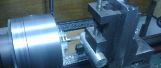
Cutting blanks
The operations of completely separating part of the material from the workpiece, dividing the workpieces into separate parts, as well as the formation of one or several dimensional narrow grooves (slots, splines) are carried out with cutting and slotting cutters. The diameter of the cutting cutter should be chosen as small as possible. The smaller the diameter of the cutter, the higher its rigidity and vibration resistance. Workpieces are most often installed and secured in a vice (Fig. 5.28). It is preferable to cut thin sheet material and cut it into strips using down milling and small feeds (S_= 0.01…0.08 mm/tooth). Cutting speeds when cutting with cutting and slotting cutters made of high-speed steel, depending on the depth of milling and feed per tooth of the cutter, are: when processing workpieces made of gray cast iron v=12...65 m/min; from malleable cast iron - 27...75 m/min; made of steel - 24...60 m/min.
Types and applications
Key cutters are widely used in mechanical engineering, metal processing, woodworking, machine tool building, equipment repair and other activities. The main purpose of the tool is to mill keyways in the manufacture of shafts. They are also used for preparing dimensional recesses and longitudinal grooves in the production of various steel and cast iron products.
Key cutters vary in material used. Most often this is high-speed steel R6M5. It is less common to find tools made from P18 steel; equipment was made from it during Soviet times and these cutters are still in great demand. P18 cutters work great even with hardened steel. The hardness of the tool is about 65 HRC.
For processing products made from hard and hardened steel grades, cutters with tipped parts from VK8 and other carbide metals (T15K6, T5K10) are used. Their durability is significantly superior to conventional tool steel. Tools are also available with a special anti-corrosion coating made of titanium carbide; they can be distinguished by their characteristic yellow tip. This solution allows you to preserve the tool longer, especially when used in conditions of high humidity.