Gearbox type Gear ratio [I] Gearbox torque Service factor (service factor) Drive power Efficiency factor (Efficiency) Explosion-proof versions Reliability indicators Drive calculation service
This article contains detailed information on the selection and calculation of a gearmotor. We hope the information provided will be useful to you.
When choosing a specific gearmotor model, the following technical characteristics are taken into account:
- gearbox type;
- power;
- output speed;
- gear ratio;
- design of input and output shafts;
- type of installation;
- additional functions.
Changing the speed of an asynchronous motor. Analysis of regulation methods.
Due to their simplicity of design, relative cheapness and reliability, three-phase motors are widely used in households and production. Many actuators use all kinds of asynchronous motors. For a wide range of IM applications, it is necessary to change and regulate the speed of rotation of the motor shaft. Blood pressure speed can be adjusted in several ways. We will look at them now.
- Mechanical regulation. By changing the gear ratio in the gearboxes.
- Electrical regulation. Changing several parameters of the supply voltage.
Let's consider the electrical change in blood pressure speed as a more accurate and common method of regulation.
Control of electrical parameters allows you to start the engine smoothly and maintain the specified speed or torque parameters of an asynchronous motor.
Parameters used to control the motor:
The most common asynchronous motor is the squirrel wheel motor, a motor with a squirrel cage rotor. To control rotation in this type of electrical machines, several types of influence are used.
How to calculate a gearbox for reducing speed
How to calculate the gear ratio of a mechanical transmission.
In this article I will give an example of calculating the gear ratio of gears of different diameters, with different numbers of teeth. This calculation is used when it is important to determine, for example, the speed of rotation of the gearbox shaft with a known drive speed and tooth characteristics.
Naturally, it is possible to measure the rotation speed of the output shaft, but in some cases a calculation is required. In addition, in theoretical mechanics, when designing various components and mechanisms, it is necessary to calculate gears in order to obtain a given rotation speed.
The term gear ratio is highly ambiguous. It echoes the term gear ratio, which is not entirely true. When we talk about the gear ratio, we mean how many revolutions the driven wheel (gear) will make relative to the drive one.
To properly understand the processes and structure of the gear, you should first familiarize yourself with GOST 16530-83.
So, let's look at an example of a calculation using two gears.
To calculate the gear ratio we must have at least two gears. This is called a gear train. Typically, the first gear is the driving gear and is located on the drive shaft, the second gear is called the driven gear and rotates into engagement with the driving gear. In this case, between them there may be many other gears, which are called intermediate gears. To simplify the calculation, consider a gear train with two gears.
In the example, we have two gears: driving (1) and driven (2). The easiest way is to count the number of teeth on the gears. Let's count the number of teeth on the drive gear. You can also look at the markings on the gear housing.
Let's imagine that the drive gear (red) has 40 teeth, and the driven gear (blue) has 60 teeth.
Divide the number of teeth on the driven gear by the number of teeth on the drive gear to calculate the gear ratio. In our example: 60/40 = 1.5. You can also write the answer as 3/2 or 1.5:1.
This ratio means that the red, driving gear must make one and a half revolutions in order for the blue, driven gear to make one revolution.
Now let's complicate the task by using more gears. Let's add another gear with 14 teeth to our gear train. Let's make her the leader.
Let's start with the yellow drive gear and work our way towards the driven gear. For each pair of gears we calculate its gear ratio. We have two pairs: yellow-red; red-blue. In each pair we consider the first gear as the driving gear, and the second as the driven one.
In our example, the gear ratios for the idler gear are: 40/14 = 2.9 and 60/40 = 1.5.
We multiply the values of the gear ratios of each pair and get the total gear ratio: (20/7) × (30/20) = 4.3. That is, to calculate the gear ratio of the entire gear train, it is necessary to multiply the gear ratio values for the intermediate gears.
Let us now determine the rotation frequency.
Using the gear ratio and knowing the speed of the yellow gear, you can easily calculate the speed of the driven gear. Typically, rotational speed is measured in revolutions per minute (RPM). Consider the example of a gear train with three pinions. Let's assume that the speed of the yellow gear is 340 rpm. Let's calculate the rotation frequency of the red gear.
We will use the formula: S1 × T1 = S2 × T2,
S1 – rotation speed of the yellow (drive) gear,
Т1 – number of teeth of the yellow (drive) gear;
S2 - rotation speed of the red gear,
Т2 – number of teeth of the red gear.
In our case, we need to find S2, but using this formula you can find any variable.
It turns out that if the driving, yellow gear rotates at a frequency of 340 rpm, then the driven, red gear will rotate at a speed of approximately 60 rpm. In the same way, we calculate the rotation frequency of the red-blue pair. The result obtained - the rotational speed of the blue gear - will be the desired rotational frequency of the entire gear train.
Gearbox type
The presence of a kinematic drive diagram will simplify the choice of gearbox type. Structurally, gearboxes are divided into the following types:
Single-stage worm gear with crossed input/output shaft arrangement (angle 90 degrees).
Two-stage worm gear with perpendicular or parallel arrangement of the axes of the input/output shaft. Accordingly, the axes can be located in different horizontal and vertical planes.
Cylindrical horizontal with parallel input/output shafts. The axes are in the same horizontal plane.
Cylindrical coaxial at any angle. The shaft axes are located in the same plane.
In a bevel-helical gearbox, the axes of the input/output shafts intersect at an angle of 90 degrees.
IMPORTANT! The spatial location of the output shaft is critical for a number of industrial applications.
- The design of worm gearboxes allows them to be used in any position of the output shaft.
- The use of cylindrical and conical models is often possible in the horizontal plane. With the same weight and dimensional characteristics as worm gearboxes, the operation of cylindrical units is more economically feasible due to an increase in the transmitted load by 1.5-2 times and high efficiency.
Table 1. Classification of gearboxes by number of stages and type of transmission
| Gearbox type | Number of steps | Transmission type | Axes location |
| Cylindrical | 1 | One or more cylindrical | Parallel |
| 2 | Parallel/coaxial | ||
| 3 | |||
| 4 | Parallel | ||
| Conical | 1 | Conical | Intersecting |
| Conical-cylindrical | 2 | Conical Cylindrical (one or more) | Intersecting/crossing |
| 3 | |||
| 4 | |||
| Worm | 1 | Worm (one or two) | Crossbreeding |
| 1 | Parallel | ||
| Cylindrical-worm or worm-cylindrical | 2 | Cylindrical (one or two) Worm (one) | Crossbreeding |
| 3 | |||
| Planetary | 1 | Two central gears and satellites (for each stage) | Coaxial |
| 2 | |||
| 3 | |||
| Cylindrical-planetary | 2 | Cylindrical (one or more) Planetary (one or more) | Parallel/coaxial |
| 3 | |||
| 4 | |||
| Cone-planetary | 2 | Conical (single) Planetary (one or more) | Intersecting |
| 3 | |||
| 4 | |||
| Worm-planetary | 2 | Worm (one) Planetary (one or more) | Crossbreeding |
| 3 | |||
| 4 | |||
| Wave | 1 | Wave (one) | Coaxial |
Frequency regulation
Special devices, frequency converters (other names: inverter, frequency converter, driver), are connected to an electrical machine. By rectifying the supply voltage, the frequency converter internally generates the required frequency and voltage values and supplies them to the electric motor.
The converter calculates the necessary parameters for blood pressure control independently, according to internal algorithms programmed by the device manufacturer.
Advantages of frequency regulation
- Smooth control of the electric motor rotation speed is achieved.
- Changing the speed and direction of rotation of the engine.
- Automatic maintenance of required parameters.
- Cost-effective control system.
The only drawback that you can put up with is the need to purchase a frequency converter. The prices for such devices are absolutely sky-high, and within 150 euros, you can get a converter for a 2 kW motor.
Regulating speed by changing the number of pole pairs
Special multi-speed motors with complex windings are controlled by changing the number of active poles on the stator. The windings of the poles are divided into groups and alternate; by commutation the windings are connected, sometimes in parallel, sometimes in series.
Positive aspects of this method.
- High motor efficiency.
- Rigid mechanical output parameters.
The disadvantages of such control include the high cost of electric machines, as well as the significant weight and dimensions of such a motor. The speed changes in steps of 1500-3000 rpm.
Asynchronous motors with wound rotor
The main way to control an IM with a wound rotor is to change the amount of slip between the stator and the rotor.
Voltage regulation
Through special LATR autotransformers, by changing the voltage on the motor windings, the shaft speed is adjusted.
This method is also suitable for IMs with a squirrel-cage rotor.
In this way, it can be adjusted from the minimum to the nominal parameters of the engine.
Installing active resistance in the rotor circuit
A variable rheostat or set of resistances in the rotor circuit affects the rotor current and field. Thus changing the amount of slip and the number of engine revolutions.
The greater the resistance, the less the current, the greater the sliding value of the blood pressure and the lower the speed.
Epilogue
For all their advantages, asynchronous machines have a significant drawback: the rotor jerks when voltage is applied. Such modes are dangerous both for the engine itself and for the drive mechanisms. Since during the start of the IM, the current in the motor windings is equivalent to a short circuit. And the jerk of the shaft breaks bearings, splines, and transmission devices. Therefore, they try to start the IM with a smooth start. Namely:
- Launch via LATR.
- Acceleration and operation of the IM, through switching the motor windings star-delta.
- Use of control devices such as frequency converter.
What types of walk-behind tractor gearboxes are there - description and features of the mechanisms
The gearboxes that modern walk-behind tractors are equipped with are divided among themselves according to their purpose. The following types of built-in mechanisms are distinguished:
- angular gearboxes - the role of this equipment is to connect the installed motor and the walk-behind tractor transmission not connected to it. This mechanism is known for its efficiency and optimal cost. If necessary, the angular gearbox for the walk-behind tractor can be modified to increase the endurance and power of the element. Another important advantage is the simple design of modern angular gearboxes for walk-behind tractors. The simple design of the mechanism allows you to assemble it yourself without spending money on expensive parts;
- reduction gearboxes - equipment of this type is designed to reduce the number of generated revolutions in order to repeatedly increase the power of the walk-behind tractor. The reduction gearbox for the walk-behind tractor built into the design of the unit operates under the control of a separate air cooling system, which guarantees uninterrupted operation of the mechanism when working in the most difficult weather conditions. Motoblocks with such gearboxes have high endurance and versatility;
- Gear reducers - the advantages of these mechanisms include fairly high gear ratios, reliability, high wear resistance and simplicity of design, which allows them to be quickly repaired without outside help. The gear reducer is very easy to use and self-maintenance;
- reverse rotation gearboxes - the operating principle of such mechanisms is called the “reversal circuit”, and gives the walk-behind tractor a lot of advantages. The main one is the ability to move at reverse speed, which significantly increases the maneuverability of the unit. Experts consider the main disadvantage of such gearboxes to be their low performance when using heavy attachments;
- worm gearboxes – the worm gearbox is made mainly from durable materials, due to which it has good characteristics and wear resistance. It shows high reliability, regardless of operating conditions.
The simplicity of the design of a modern gearbox allows you to independently manufacture such a mechanism for a household walk-behind tractor. By adhering to the correct procedure and having all the necessary materials available, the farmer will be able to make a homemade unit, which in terms of reliability and quality will be practically not inferior to its market counterparts.
Advantages and disadvantages
The use of gearboxes allows us to solve the problem of low speeds and ensure the functioning of the generator in nominal mode. At the same time, everything is somewhat more complicated than it seems at first; the use of gearboxes has many advantages and disadvantages . Let's take a closer look at them.
The advantages of gearboxes on a wind wheel include:
- the ability to significantly increase the rotation speed of the generator
- reducing the kit’s dependence on existing meteorological conditions
- if necessary, you can change the operating mode of the device, optimally prepare it for working with this equipment and wind flows
The disadvantages of gearboxes are:
- loss of power on the shaft, creating problems when starting the generator
- difficulties arise in overcoming the resistance of magnets, sticking
- the dimensions of the device create an additional barrier to the wind flow, causing unnecessary noise
- the load on the wind generator mast increases
- servicing a gearbox located at height is extremely difficult and dangerous.
- There is no possibility of high-quality repairs without lowering the mast
What is a reduction gearbox?
It is a special type of mechanism that serves as a transmission link between devices in which the active parts perform rotational motion. It is often used to transmit and convert torque from the unit that produces it to the device that uses the mechanical energy supplied to it. Unlike other types, a reduction gearbox provides a reduction in the number of revolutions and an increase in torque.
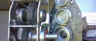
A reduction gearbox consists of a housing, gears, transmission chains, a worm mechanism, and shafts, with the help of which torque is transmitted and converted.
Toothed gears are located on the shafts in a rigid coupling, and worm gears are attached. They ensure the transfer of motion to each other, during which its transformation is carried out.
There are different types of reduction gearboxes:
Magnetic gearbox for brushless motor
In this article I will talk about the magnetic gearbox we developed. This gearbox is planned to be used in conjunction with a brushless motor. The article will talk about the possible scope of application of this gearbox, its pros and cons compared to conventional gearboxes.
Introduction
Brushless DC (BLDC) motors offer extremely high power in a minimal size.
This is achieved thanks to powerful rare earth magnets. When creating a motor in a small form factor, such motors have no competition. However, despite the high power, the small size of the motor imposes many limitations on it, such as: low torque, high operating speeds, small cooling area. These restrictions do not allow the full potential of the motor to be used. So, for example, a 540 form factor motor (D=36mm L=54mm) is capable of delivering power in excess of a kilowatt with fairly good efficiency, but this is only possible at very high speeds, when it becomes quite difficult to remove this power from the motor. In nominal mode, such a motor without forced airflow can produce 200-400 watts.
The main focus of our MotoChrome team is the design and creation of brushless motors. When designing a motor for one of the customers, we just encountered the problems described above. The customer needed a motor with a small diameter, but at the same time a fairly high torque and efficiency. To meet the requirements, the motor turned out to be almost half a meter long with a diameter of 40mm. The motor turned out to be quite expensive and very difficult to assemble. At the same time, to achieve the same power parameters, you can make the motor 3 times smaller, but using a gearbox. And in the end, this option was chosen.
Using a gearbox seems like a good solution. But many other problems arise with it, which does not allow them to be fully used in all engines.
- an additional unit with a risk of failure and a limited service life
- increase in overall dimensions;
- increased noise, which can be critical in the operation of underwater devices;
- Most mechanical gearboxes have limitations on the transmitted torque and shaft speed on the gearbox input shaft, which in turn imposes additional restrictions/requirements on the electric motor.
When selecting a gearbox, we ran into two main problems.
1) In order for the gearbox to realize the full potential of a brushless motor, it must be of a size comparable to the size of the motor. With it, the engine ceases to be compact. 2) Most mechanical gearboxes are not capable of operating at high speeds (>15000 RPM), but we are interested in high speeds. Only 1…2 companies agreed to take the order for the required gearbox and deliver it 3 months after receiving payment. We still have to find out what its reliability and durability will be, however, the difficulties associated with finding the right gearbox forced us to think about this problem further. From our point of view, a magnetic gearbox turned out to be a good option. They have not yet been widely used and there is quite a bit of information about them, so we decided to take a deeper look at this issue and make the gearbox ourselves. This will allow us to develop an approach to its modeling and will allow us to calculate its parameters in the future.
Magnetic reducer
We decided to make the magnetic gearbox according to a common scheme, which is an analogue of a planetary gearbox. Magnets in, magnets outside - “gear ring (epicycle)”, between them teeth made of soft magnetic material act as a “carriage”.
This design has a maximum holding moment in a minimum volume and is well suited to our task. As a result, we designed and manufactured the following sample.
The diameter of this sample is 36mm. The input part of the gearbox is made according to the NEMA 17 standard. Instead of the output shaft, we made a universal faceplate, which allows you to attach various loads to it in experimental work, tests and experiments, and, if necessary, install the shaft, thanks to the basic mounting hole in the center of the faceplate. By the way, we also applied the concept of universal mounts in our “Electron” motor, which we are preparing for mass production and sale in the Russian Federation (we will write a separate article about it).
The parameters of the resulting gearbox turned out to be quite close to the calculated ones. It has a reduction of 1:10 and is capable of maintaining a torque of 0.53 Nm on the output shaft under static load. This is a fairly good indicator for such dimensions. For comparison, a motor of the same dimensions will produce such a torque with an efficiency below 50%, and a system with this gearbox will have an efficiency of 80%.
In addition, the gearbox is very smooth and quiet. There are absolutely no jerks felt during rotation; the torque is transmitted very softly. This property determined the name we gave to the gearbox - “Smoother”.
Another couple of rollers with gearbox
conclusions
After initial testing, we were able to identify the following advantages of a magnetic gearbox compared to a mechanical one:
- Magnetic gearbox is quiet
- Not afraid of high speeds. The only weak link in it is the bearings, which also limit the motor.
- Long lasting. In it, as in the motor, there is nothing to break except the bearings.
- The gearbox is able to smoothly supply and maintain torque. For example, if you make a grip on such a gearbox and clamp a fragile object, then the jerk of the motor will not destroy it.
- This gearbox is protected from overloads. If the permissible load on the shaft of a mechanical gearbox is exceeded, the gears in it will collapse and jam, which can also cause damage to the motor or controller. The magnetic gearbox will simply turn and not break, and the motor will not stop.
We also identified a number of shortcomings:
- The torque of the gearbox is limited by the volume and maximum strength of the magnets. A mechanical gearbox is capable of transmitting much more torque in the same volume.
- The gearbox magnets are temperature sensitive and may become demagnetized if overheated.
- Since the gearbox uses magnets made of rare earth materials, creating large-sized gearboxes of this type is difficult.
Based on the results obtained, we have formed areas of application for gearboxes of this type:
- in biology, medicine and other procedures for grasping and moving objects, where precise positioning is required on one side (which is achieved by the backlash-free gearbox) and there is a high risk of damage to objects with which the manipulator works, for example, human tissues and organs (the softness of the output present in the magnetic gearbox) rotor and overload protection will limit the maximum impact force on the object being operated on).
- in industrial devices in which high-speed motors (electric or pneumatic) operate in confined spaces, the torque of which must be increased and the speed reduced to the required permitted value.
- in underwater devices where high demands are placed on low noise levels of the product
At the moment, testing of the gearbox continues. We test it dynamically under various loads and speeds. If everything goes well, we will be able to implement this development into a real project.
Examples of gearmotor selection
Example No. 1
Initial data:
Conveyor for bulk materials
Required torque on output shaft M2 = 150 Nm
Asynchronous electric motor n1, =1400 rpm
Speed at the output shaft of the gearbox n2 = 70 rpm
Continuous operation, irreversible, medium-force shocks
Radial cantilever load applied in the middle of the landing part of the ends of the output shaft F out = 500 N
Average daily work 7 hours
Number of starts per hour up to 10
Environmental conditions: temperature up to 30oC
- Gear ratio i = n1/n2 = 1400/70 = 20
- We select the service factor from the table of the average operating mode, using data on daily operation and the number of starts, determined by interpolation fs = 1.25
- We increase the service factor using the temperature coefficient fs = 1.25 x 1.1 = 1.38
- We consider M2n = M2 x fs = 150 x 1.38 = 207 Nm
- We select an NMRV 90-20 gearbox with a 2.2 x 1400 engine with a gear ratio i=20, developed torque M2n = 249 > 207 Nm, table service - factor fs = 1.4 > 1.38.
Example No. 2
Initial data:
Stirrer for adhesive mixture
Electric motor power P1 = 1.5 KW
Asynchronous electric motor n1, =900 rpm
Speed at the output shaft of the gearbox n2 = 60 rpm
Difficult working conditions. Continuous operation, non-reversing, without shocks
Average daily work 16 hours
Number of starts per hour up to 100
Environmental conditions: temperature up to 20oC
- Gear ratio i = n1/n2 = 900/60 = 15
- We select the service factor according to the heavy-duty table, using data on daily operation and the number of starts, determined by interpolation fs = 1.9
- Taking into account the temperature coefficient, the service factor will be fs = 1.9 x 1.0 = 1.9
- We consider P1n = P1 x fs = 1.5 x 1.9 = 2.85 KW
- We select a NMRV 110-15 gearbox with a 3.0 x 900 engine with a gear ratio i=15, power P1n = 3.0 > 2.85 KW, table service factor fs = 1.9 ≥ 1.9.
What is the gearbox used for?
The optimal generator rotor speed for generating electric current is about 2000 rpm. There are also less high-speed types of generators, but in any case, for high-quality operation, the wind wheel must give the generator rotor a sufficiently high speed. Existing conditions rarely allow high values to be obtained.
In winds of 6-8 m/s, the rotation speed of the wind wheel is not capable of ensuring the nominal operating mode of the generator, which reduces the efficiency of the entire set.
The solution to the problem is to install a gearbox between the impeller and the rotor of the overdrive generator. It increases the rotation speed of the generator due to a single or multi-stage increase in rotation speed, for which a pulley system or planetary (differential) type device is used.
When using a gearbox, one rotation of the impeller accounts for several revolutions of the generator shaft. If the gearbox design is multi-stage, then the gear ratio can be increased tens of times, although this is fraught with loss of power.
It must be taken into account that the gearbox allows you to obtain a high rotation speed due to a sharp (proportional to the gear ratio) drop in power on the shaft. To achieve high speed in this case means losing the force that allows you to initiate rotation of the rotor, move the tight shaft from its place, and overcome sticking magnets.
It is not advisable to use gearboxes with a large gear ratio for wind generators, since the performance of the complex suffers from the loss of power.
Preliminary preparation
Before you begin creating this device, you must have general knowledge of mechanics, be able to use repair tools and equipment, and know the operating principle and structure of this unit.
In addition, you need to initially determine:
- the type of future gearbox and its version;
- the gear ratio that will need to be converted and determined at the output;
- indicators of dynamic loads that will affect the working parts of the device;
- weight and dimensions of the future device;
- installation angle;
- temperature limits that will occur in the device during its operation;
- switching cycle – full or variable;
- intensity of operation.
More details about the components
The assembly process is not as complicated as the selection or production of spare parts necessary for such a gearbox.
- Device body. In industry it is produced by casting. The necessary holes are made using high-precision equipment, since it is necessary to achieve the mutually correct arrangement of the shafts and the alignment of the stars. When producing it, it is necessary to make the top cover removable. This will facilitate and simplify the process of servicing it during operation;
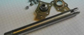
- Shafts and axles of the gearbox. They support gears and are used if they need to be equipped with this device. Installation is carried out by pressing onto splines or keys. For their manufacture, it is better to use durable steel measuring from 10 to 45 mm, which is easy to machine;
- Bearings. They are used as supports for shafts and resist loads and provide the possibility of rotational movement. Its reliability, durability and performance depend on the correct selection of these gearbox elements. If you are installing spur gears, then it will be sufficient to install conventional single or double row ball bearings. If a helical bearing or worm gear will be installed, then a roller or angular thrust ball bearing will be the best option. It is better to buy new ones than to use them from disassembly;
- Gears. They provide a change in the rotation speed of the shafts and, naturally, a reduction in the gear ratio. For their production, special metal-cutting equipment is used, which home workshops are not equipped with. The dimensions and characteristics of other parts included in this unit, as well as the distance between the axles and shafts, depend on the size of the gears. When installing, it is important to correctly set the gap between them. I-20 oil is perfect for lubricating gears. It is filled to the level of the bottom of the gears. Other parts of the device are lubricated by spraying lubricant onto them. You can take it from disassembly or buy new ones;
- Oil seals. They prevent oil from leaking out of the device body. They are installed at the exit points of the shafts on bearings under the covers. Are bought;
- Safety coupling. It is designed to prevent destruction of the device when excessive loads occur. Buyable;
- Bearing caps. They can be different - deaf and through. Designed to facilitate maintenance and installation of bearings. You can grind them yourself or find them at a disassembly site.
Maintenance
Any gearbox needs lubrication, so some farmers are interested in: “What kind of oil should I pour into the gearbox of a walk-behind tractor?” Typically this type of information is contained in the user manual. Manufacturers themselves determine which type of oil is suitable for their equipment.
If you installed a homemade unit, we recommend using MOTUL products. This is a well-known manufacturer of oils that are optimally suited for walk-behind tractors.
However, even timely oil changes cannot protect the gearbox from breakdowns. Let's look at a few of the most likely reasons. For example, in the MB Compact walk-behind tractor there is a knocking sound in the gearbox. What is this connected with?
- The axle axle disconnection unit has failed. In this case, it is necessary to disassemble the gearbox and replace worn-out parts. In addition, knocking can be caused by incorrect drive settings; this can be eliminated by changing the cable tension.
- Circuit break. Such a breakdown is usually accompanied by a characteristic knock, followed by jamming of the gearbox. The malfunction is eliminated by replacing the broken chain.
These are not the only problems that can arise with the gearbox of the MB-Compact walk-behind tractor. Oil leaks indicate wear of the rubber seals.
To eliminate the malfunction, you need to disassemble the gearbox and replace the element. In some cases, it is impossible to record the transmission of the walk-behind tractor. There could be several reasons:
To ensure that the gearbox does not require repairs for a long time, the product must undergo a run-in process followed by changing the oil in the system.
In addition, during operation of the walk-behind tractor, you need to monitor the oil level in the gearbox and try to avoid shock loads.
When replacing worn parts, it is recommended to purchase only original spare parts from the manufacturer.
Read also: Thread hole diameter 1 inch
One of the most important mechanisms of a modern walk-behind tractor is the gearbox built into its design, the function of which is to continuously transmit the generated torque from the engine to the wheels of the agricultural machine used. The gearbox plays a fairly important role in the design of the walk-behind tractor, so every owner of the equipment should know how to independently lubricate and repair the mechanism if it breaks down.
Stages of work to create this device
- Installation of drive sprockets on the input shaft. In this case, installation can be done by spot welding, flange or key connection;
- Assembly of driven shaft axles;
- Installation of the driven sprocket;
- The case can be picked up from disassembly and adjusted or made by yourself. At the same time, it is necessary to make technological holes in it for oil seals and bearing connections;
- Installation of closed type ball bearings. An excellent option would be cylindrical ones. Their installation is carried out by tension;
- The drive shaft is mounted on eccentric bearing supports with the ability to adjust the chain tension by at least 15 degrees;
- At the final stage, a lid with a sealing gasket is installed.
Having decided to do this, it is better to first assess your strengths, knowledge and skills in handling the tool, so as not to get into trouble by spending a decent amount of money, a lot of time and effort, and at the same time, without creating the necessary device, but if you are an existing or former mechanic, you can safely get down to business.
Chain Gearbox, Repair and DIY Manufacturing, Lubrication, Assembly and Disassembly
The chain gearbox is one of the most popular types for use in walk-behind tractors.
How to make it yourself, and what criteria are used to calculate it. The gearbox is an integral part of walk-behind tractors, cultivators and other garden equipment.
This is a complex mechanism that is a transmission link that is located between the rotation devices of an electric motor or internal combustion engine to the final operating unit.
Among the main indicators that a chain gearbox has are:
- Transmitted power;
- Efficiency;
- Number of driving and driven rotation shafts.
Gear drives are attached to the rotating devices, which transmit, lower and regulate the movement of the chain conveyor drive.
What is a gearbox?
This mechanism is a transmission link that is located between the rotational devices of an electric motor or internal combustion engine to the final operating unit.
The main characterizing indicators of the gearbox are:
- transmitted power;
- efficiency;
- number of driving and driven rotary shafts.
Gear or worm gears are fixedly attached to the rotational devices of this mechanism , which transmit and regulate movement from one to another. The housing has holes with bearings on which the shafts are located.
Preliminary preparation
Before you begin creating this device, you must have general knowledge of mechanics, be able to use repair tools and equipment, and know the operating principle and structure of this unit.
In addition, you need to initially determine:
- the type of future gearbox and its version;
- the gear ratio that will need to be converted and determined at the output;
- indicators of dynamic loads that will affect the working parts of the device;
- weight and dimensions of the future device;
- installation angle;
- temperature limits that will occur in the device during its operation;
- switching cycle – full or variable;
- intensity of operation.
How to make a gearbox with your own hands?
The most important part of a reduction gearbox is its housing. It must be designed and manufactured correctly with your own hands, since the relative position of the shafts and axes, the alignment of the seats for support bearings and the clearances between gears depend on this.
Industrial gearbox housings are made mainly by casting from aluminum alloys or cast iron , however, this is completely impossible to do at home.
Therefore, you can select or modify a ready-made housing to suit your needs, or weld it from a steel sheet.
Only in this case should you remember that during the welding process the metal can “lead”, and therefore, to maintain the alignment of the shafts, it is necessary to leave an allowance.
Many masters do it differently.
In order not to bother with boring work, they begin to weld the body completely, and instead of sockets for support bearings they use pipe sections , which are set in the required position and only after that are finally secured in place by welding or bolts. To facilitate maintenance of the gearbox, it is necessary to make a removable top cover at the housing, and a drain hole at the bottom, which will be used to drain used oil.
The gears are supported by the axles and shafts of the gearbox. Typically, in a single-stage mechanism, only shafts with rigidly mounted gears are used. In this case, both gears rotate together with their shafts. The axle is used when it is necessary to insert an intermediate gear into the gearbox.
It begins to rotate freely on its axis with minimal clearance , and to prevent it from moving sideways, it is fixed with a nut, a thrust collar or locking split washers.
Shafts should be made of steel, which has good strength and excellent machinability.
The bearings in the gearbox serve as supports for the shafts. They perceive the loads that arise during the operation of the mechanism. The reliability and performance of the gearbox depends entirely on how correctly the bearings were selected.
For a do-it-yourself mechanism, it is best to choose closed type bearings , which require minimal maintenance. They are lubricated with grease. The type of bearings directly depends on the type of load.
When using spur gears, ordinary single or double row ball bearings will suffice.
If the mechanism contains helical gears or worm gears, then an axial load begins to be transmitted to the shaft and bearings, which requires the presence of a ball or roller angular contact bearing.
Another quite important part of the gearbox is the gears. Thanks to them, you can change the rotation speed of the output shaft. To make gears, you need special metal-cutting equipment, so to save money you can use ready-made parts from decommissioned devices.
It is very important during the installation of gears to set the correct gap between them, because the noise level that occurs during operation of the gearbox and the load capacity depend on this.
It is best to lubricate the gears with liquid industrial oil, which is poured in such a way that it covers the teeth of the lower gear.
The remaining parts are lubricated by spraying oil throughout the internal cavity of the mechanism.
Stages of work to create this device
- Installation of drive sprockets on the input shaft. In this case, installation can be done by spot welding, flange or key connection;
- Assembly of driven shaft axles;
- Installation of the driven sprocket;
- The case can be picked up from disassembly and adjusted or made by yourself.
At the same time, it is necessary to make technological holes in it for oil seals and bearing connections; - Installation of closed type ball bearings.
An excellent option would be cylindrical ones. Their installation is carried out by tension; - The drive shaft is mounted on eccentric bearing supports with the ability to adjust the chain tension by at least 15 degrees;
- At the final stage, a lid with a sealing gasket is installed.
Having decided to do this, it is better to first assess your strengths, knowledge and skills in handling the tool, so as not to get into trouble by spending a decent amount of money, a lot of time and effort, and at the same time, without creating the necessary device, but if you are an existing or former mechanic, you can safely get down to business.
Scope of application of the gearbox
This mechanism is an indispensable assistant in various fields of human activity. Typically it is used:
- in industry;
- in automobile gearboxes;
- in electrical equipment and household appliances;
- in the gas industry and many other industries.
This mechanism is used very widely in industry. In various processing machines it is used as a rotary transmission part that increases the speed of rotation.
Homemade bevel gear for walk-behind tractor
The design of the gearbox is not particularly complicated, and it is quite possible to assemble it yourself. First, the rated power is calculated: (Pn); Pn = Pe (hp) x FS, which will allow you to correctly determine the angle of the bevel gear.
Using the same principle, the number of possible revolutions per minute and the calculation of torque are calculated. A self-made device needs to determine operating conditions, including the radial or axial load of the shafts at their ends. Operation is optimal with the correct selection of temperature and lubricant.
The assembly is performed after these above steps. You can take the factory building . Its diameter will tell you what the bearing housing for the shaft should be like. A good quality drill and caliper will help here. Next, take two bearings under the shaft.
The steel flange is installed on the front part . A flange bearing and washer are located inside. The flange is attached to the generator with screws. The steel key with the drive gear and the driven gear shaft are selected in advance.
Units connected to the transmission mechanism to the rotary generator It has a pulley that provides V-belt transmission. It is secured to the driven shaft with a nut and spring washer.
Main elements of the gearbox
In the automotive industry, angular gearboxes are often used, because these units provide efficient operation. The angular gearbox ensures the coupling of the transmission to the engine. You can modify an already finished product. Among the main elements of the gearbox are:
Read also: Makita hr2450 rotary hammer do-it-yourself repair
- Flange.
- Generator housing.
- Pulley with V-belt drive.
- Pulley fastening.
- Steel washer.
- Rotor shaft.
- Steel key.
- Flange bearing.
- Flange mounting.
It’s quite easy to understand the gear device by looking at its transmission, which is the transmitter between the wheels and the motor. The direction changes in the walk-behind tractor. A transmission is a gearbox with a clutch . It is often used in heavy walk-behind tractors.
Main elements of the walk-behind tractor design
- Bed or frame. A motor, a transmission system to the wheels, a traction device for attachments and a suspension are mounted on it.
- Power unit. Power - 5−10 l. With. Engines from motorcycles, mopeds, compressors and chainsaws are used.
- Suspension. Usually primitive: from homemade wheels or ready-made wheels from agricultural machinery. Sometimes motorcycle and car wheels are used. It can be portal or axial.
- Gearbox for walk-behind tractor. Serves to reduce drive shaft speed with a simultaneous linear increase in torque. A gearbox from a scooter or car is often used as a gearbox.
A homemade device does not require pairing with an engine , because the calculation is made for specific tasks, and there are no restrictions due to a ready-made technical solution.
Peculiarities
The simplest option is to use two pulleys with different diameters . One, larger one, is installed on the wind wheel shaft. It, through a V-belt transmission, transmits rotation to a smaller pulley mounted on the generator shaft. The rotation speed increases by an amount proportional to the ratio of the pulley diameters.
Such a transmission can have several stages, for example, from the wind wheel shaft to the intermediate pulley, and from there to the generator pulley. Each gear gives an increase in rotation speed, but reduces power in proportion to the gear ratio. This can negatively affect the operation of the generator - a weak force on the shaft will not be able to force it to start rotating, overcome sticking and other resistance of the rotor.
The gearbox option with a V-belt drive is the simplest and most reliable; it can be manufactured and assembled independently.
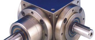
A more complex type of gearbox that cannot be manufactured independently is planetary. It is a gear system consisting of:
- ring gear (epicycle), which is a circle with teeth directed inward. Its diameter is the largest; all other gears are located inside. It receives the initial torque and transmits it sequentially
- satellites are gears of relatively small diameter that mesh with the central (final) gear or with other satellites
- the carrier is a circle on which the axes of the satellites are located
- sun (central) gear. It receives the impulse from the satellites, rotating at a speed determined by the gear ratio
Planetary gearboxes are highly compact; the absence of open parts eliminates the risk of element failure. Metal parts are protected from corrosion, the possibility of any failures or malfunctions is minimal. At the same time, it is extremely difficult to make a homemade planetary gearbox, and it is quite expensive to purchase.
For use on horizontal wind generators, a planetary gearbox is preferable, since it is more reliable, more compact and does not require constant maintenance, while homemade V-belt devices constantly experience some kind of failure (belts break, shafts get jammed and other problems).
Where is the device used?
A reduction gearbox has many advantages. Its design allows you to increase the productivity and profit of large industrial enterprises. It can also be considered an indispensable assistant in the household.
Experts highlight the following areas of application of the device:
- in industry;
- in car gearboxes;
- in various electrical equipment.
At large enterprises this product is used quite widely. In various machines for metal processing, the gearbox is used as a rotary transmission unit, which increases the number of revolutions. In gearboxes for automobile transport, a device is installed that reduces the engine speed. The softness and smooth running of the machine directly depends on the quality of adjustment of the gears of the gearbox.
This product is widely used in electrical equipment and household appliances, such as rotary hammers, drills or mixers. Gearboxes can be considered the main parts of ventilation, planetary, pumping and cleaning systems, because they are able to maintain optimal operating pressure.
Mechanical devices of different types
The use of wind generators in conditions of weak and moderate winds, typical for most regions of Russia, creates special requirements for the rotor design. At low flow rates, the windmill impeller rotates too slowly to generate sufficient electricity.
It is almost impossible to increase the rotation speed of a windmill.
The use of more sensitive types of impeller has little effect on the speed; only the possibility of starting from a weaker wind changes, which does not give a significant effect. To solve the problem, different types of mechanical devices are used - gearboxes .
Worm gear reversibility
This parameter determines whether the input shaft can rotate when a certain torque is applied to the output shaft.
The reversibility of a worm gearbox depends on numerous factors, including helix angle, gear ratio, lubrication, temperature, worm surface finish, vibration, etc.
The reversibility of a worm gearbox directly depends on the efficiency (static or dynamic).
The ability to do this and the force at which this happens determines the degree of reversibility of the gearbox
When using a gearbox to move loads, high reversibility prevents inertia of moving parts, which avoids peak load on the drive
In the case of using a gearbox for lifting loads, high irreversibility is selected in the absence of a brake on the motor shaft. ATTENTION: only an external braking device can prevent the load from slipping.
The table provides background information on various degrees of reversibility/irreversibility of gearboxes regarding dynamic ŋd and static ŋs efficiency
| ŋd | Dynamic reversibility and irreversibility |
| > 0.6 | Dynamic reversibility |
| 0.5-0.6 | Variable dynamic reversibility |
| 0.4-0.5 | Durable dynamic reversibility |
| 0.55 | Static reversibility |
| 0.5-0.55 | Variable static reversibility |
In practice, gear oil is considered the most optimal means for lubricating the gearbox. This composition is able to prevent various breakdowns of the mechanism and protect its rubbing parts when working in difficult conditions. Transmission oils of the ZIC 10W40 brand are considered one of the leaders in the domestic market - this semi-synthetic material covers the gearbox parts with a thin film and protects them from wear. Changing the oil in a walk-behind tractor - how to do it yourself?Immediately before performing the procedure, the walk-behind tractor gearbox will need to be cleaned of old lubricant. This is not difficult to do - in some cases it will be necessary to disassemble and dismantle certain parts of the walk-behind tractor, however, most units have free access to the gearbox drain cover. The procedure for changing the oil is as follows:
Read also: DIY cardboard shredder If the agricultural implement is used extremely intensively, then this procedure will need to be performed every 50 hours of work done. In all other cases, a one-time replacement of the product for every 100 hours of operation of the unit is sufficient. How much oil to fill in the gearbox of a walk-behind tractor?Immediately before pouring new oil, you need to find out how much old material is poured into the gearbox. This is done in this order:
After this, you need to calculate the length of the wire coated with oil. If the product is approximately 30 cm deep in the lubricant, then this is considered the optimal amount of oil that needs to be poured into the gearbox when replacing. If the homemade sciat turned out to be completely dry, then you will need to pour at least 2 liters of previously unused transmission lubricant into the walk-behind tractor gearbox. |
Do-it-yourself gearbox that increases speed - Metals, equipment, instructions
The walk-behind tractor used by land owners consists of several components and parts. It is easy to operate. Users are often interested in questions about what a gearbox for a walk-behind tractor is, what kind of oil to put in it, and whether this device can be made independently.
How does a walk-behind tractor gearbox work?
A gearbox, often called a converter, is a mechanism that processes the torque of the motor and transmits it to the power take-off shaft of the walk-behind tractor.
This happens with the help of a set of gears located in a durable metal casing. The gearbox and the quality of its parts affect the service life of the unit for agricultural work.
Therefore, when buying a walk-behind tractor in a store, you should pay great attention to its components, including the gearbox design.
The gearbox can be collapsible or non-dismountable. The latest models are installed on budget-type walk-behind tractors. The parts in them are cheap and cannot be repaired. In case of malfunctions, the gearbox must be replaced.
During normal operation, their service life is measured in 1-2 seasons. On expensive equipment, the engine is equipped with a converter of a collapsible design. It serves well for several seasons.
If individual parts break down, the failed part is simply replaced.
A converter of any type may include:
- housing (collapsible or not);
- gears and shafts;
- stars;
- belts or chains;
- bearings.
With the help of the listed parts, movements are transmitted from the motor to the mounted implements. The chain is put on the sprockets, the belt is put on the pulleys. The simplest mechanisms are equipped with a belt drive. They are also considered the weakest and most unreliable.
When the torque is high, the belts slip and fly off the pulleys. But this design has a beneficial effect on the motor shaft. Belt slippage can be avoided by replacing them with toothed ones. With this replacement, the pulleys also need to be replaced.
What types of gearboxes are there for a walk-behind tractor?
Gearboxes are divided into types:
- angular;
- downward;
- gear;
- worm;
- chain;
- combined.
All of them find their application on walk-behind tractors of various types.
Angular
The angular gearbox for the walk-behind tractor ensures the coupling of the engine with the transmission and attachment mechanism. Another device is also used, if modified. The corner device consists of the following parts:
- flange;
- flange mounting;
- bearing;
- frame;
- pulley;
- belt;
- steel washer;
- pulley fastening;
- key;
- rotor shaft.
You can make this device yourself. Before work, it is necessary to take into account the conditions in which he will work. These are radial and axial loads at the ends of the shafts. The load depends on the type of lubricants and temperature. It is best to choose a factory-made case. Bearings of the required size are selected for the shaft.
Downward
A reduction gearbox for a walk-behind tractor, either self-made or industrially manufactured, is designed to increase the power of an agricultural unit. This may be necessary when operating the walk-behind tractor on sandy soil, when the wheels begin to slip. It is used on gasoline and diesel vehicles equipped with an air cooling system.
You can reduce the number of revolutions and increase the power of the drive mechanism using reduction gearboxes, which are sometimes called creepers for a walk-behind tractor.
They are considered the most reliable for operating a diesel or gasoline air-cooled walk-behind tractor. When the unit is operating, the number of revolutions decreases.
This allows you to use the walk-behind tractor for particularly difficult work, for example, plowing heavy soil or harvesting potatoes using a potato digger.
Gear
A gear converter with a differential is used in heavy-duty walk-behind tractors. It is well suited to engines with a vertical crankshaft.
The gearbox produces little noise during operation and has high performance. It is capable of functioning in straight and angular patterns. Gears are used both bevel and cylindrical.
The device requires the constant presence of oil in the crankcase, but this feature is compensated by its high power.
https://www..com/watch?v=nbsbV-c48cg
On heavy units, the gear converter is often equipped with a gearbox. This transmission allows the walk-behind tractor to move in reverse. Reverse occurs during reverse rotation of the gears in the housing. This is achieved by changing the position of the lever outside the housing.
Gear reducer is the best choice for heavy agricultural machinery. An engine equipped with this mechanism runs longer than with a worm version.
Worm
Worm gearboxes are widely used in mini-tractors and walk-behind tractors. This model has gained popularity due to its long period of trouble-free operation and high reliability.
The worm-type device has a reverse, allowing the unit to move in reverse. A distinctive feature of this converter is the presence of a special screw and worm wheel. The thread profile on the parts is trapezoidal.
They are made from high-strength materials.
The screw can have a four-start thread or a two-start thread. It matches the thread on the gear. The teeth on high-quality parts are made of anti-friction steel. The efficiency of the device is high. Its advantages:
- the gearbox allows you to extend the service life of the engine;
- creates little noise during operation;
- The device consists of only 2 parts;
- has a large gear ratio;
- has a smooth ride;
- high self-braking effect.
All positive qualities appear with precise assembly and adjustment of the mechanism.
Chain
A chain device must have a chain in its design. Sometimes it occurs not just one, but in several pieces. The gear chain is put on the sprockets and ensures their rotation.
The device is easy to use, has a reverse function and a high degree of reliability. The operating principle is similar to a belt mechanism. Changing the gear ratio is easy by changing the sprocket sizes.
They work like a bicycle, but in reverse: the small one is the driving sprocket, and the large one is the driven sprocket.
Reliability of operation is ensured by the quality of the metal of the sprockets and the strength of the chain. When making your own gearbox, you should use motorcycle sprockets; they are much stronger than bicycle sprockets. The design of the product is simple and reliable, it has a reverse function. The chain requires constant lubrication and tightening. Its rupture is a common cause of gearbox failure. To repair, you need to change the chain.
Combined
The combined gearbox combines gear and worm, worm and cylindrical gears. It can be single-stage or multi-stage. The single-stage mechanism has a gear ratio of up to 7. The body is made of cast iron or welded aluminum. Two-stage devices have a gear ratio of up to 40, three-stage - up to 150.
All of them are designed to change the speed of rotation of the engine shafts and the power take-off shaft. All types of gears are placed in a single housing. The combined mechanism is the most practical. Despite its small size, it has high quality and low cost.
Creeper
The traction of the wheels of a tillage machine with the soil can be enhanced if you use lugs or a creeper for a walk-behind tractor. The creeper is one of the mounted devices.
It makes it possible to reduce the speed of the agricultural unit and increase traction force along with torque. An analogue of a gearbox operates using a chain and sprockets on the shafts.
Each considered converter has its own disadvantages. To reduce their number to a minimum, you should try to make the device yourself. A homemade item can be of higher quality and easier to use than a purchased item.
How to make a gearbox for a walk-behind tractor with your own hands
A homemade gearbox for a walk-behind tractor requires preparation of tools for manufacturing. For fruitful work you will need:
- screwdrivers of different sizes;
- hacksaw for metal;
- pliers;
- bench vice;
- welding machine;
- hammers of different weights;
- rubber for gaskets;
- drill with drills.
DIY assembly
Experts say that making a small-sized worm gear with your own hands is quite troublesome, but it is possible. The device should increase the torque of the working shaft of the walk-behind tractor and reduce its number of revolutions. The maximum performance of the machine directly depends on the product.
The walk-behind tractor uses a reverse manual gearbox, which makes it possible to change speeds. The factory gear ratio is sometimes very small. The designers equipped the unit with a small sprocket on the operating shaft of the gearbox. Interacting with a large star from the wheel of the device, it ensures a decrease in engine speed. An additional sprocket must be put on the working shaft located in the bearing platform. It will transmit torque through the second chain to the wheels of the walk-behind tractor.
Thus, you can assemble a reduction gearbox for an electric motor with your own hands, which will have high torque and a two-stage reduction in the number of engine revolutions. Using a gearbox from any motorcycle, it becomes possible to adjust the speed without pressing the gas handle. The engine will almost always operate at low speeds and fail less.
You can make a bevel gear with your own hands from an old scooter or tractor. In this case, the wheeled platform is not used.
It is necessary to install cultivator rollers on the bridge. This option provides optimal operating power and travel speed.
Gearbox for a windmill: making it yourself, advantages and disadvantages of the device
The use of wind generators in conditions of weak and moderate winds, typical for most regions of Russia, creates special requirements for the rotor design. At low flow rates, the windmill impeller rotates too slowly to generate sufficient electricity.
It is almost impossible to increase the rotation speed of a windmill.
The use of more sensitive types of impeller has little effect on the speed; only the possibility of starting from a weaker wind changes, which does not give a significant effect. To solve the problem, different types of mechanical devices are used - gearboxes .
What is the gearbox used for?
The optimal generator rotor speed for generating electric current is about 2000 rpm. There are also less high-speed types of generators, but in any case, for high-quality operation, the wind wheel must give the generator rotor a sufficiently high speed. Existing conditions rarely allow high values to be obtained.
In winds of 6-8 m/s, the rotation speed of the wind wheel is not capable of ensuring the nominal operating mode of the generator, which reduces the efficiency of the entire set.
The solution to the problem is to install a gearbox between the impeller and the rotor of the overdrive generator. It increases the rotation speed of the generator due to a single or multi-stage increase in rotation speed, for which a pulley system or planetary (differential) type device is used.
When using a gearbox, one rotation of the impeller accounts for several revolutions of the generator shaft. If the gearbox design is multi-stage, then the gear ratio can be increased tens of times, although this is fraught with loss of power.
It must be taken into account that the gearbox allows you to obtain a high rotation speed due to a sharp (proportional to the gear ratio) drop in power on the shaft. To achieve high speed in this case means losing the force that allows you to initiate rotation of the rotor, move the tight shaft from its place, and overcome sticking magnets.
It is not advisable to use gearboxes with a large gear ratio for wind generators, since the performance of the complex suffers from the loss of power.
Peculiarities
The simplest option is to use two pulleys with different diameters . One, larger one, is installed on the wind wheel shaft. It, through a V-belt transmission, transmits rotation to a smaller pulley mounted on the generator shaft. The rotation speed increases by an amount proportional to the ratio of the pulley diameters.
Such a transmission can have several stages, for example, from the wind wheel shaft to the intermediate pulley, and from there to the generator pulley.
Each gear gives an increase in rotation speed, but reduces power in proportion to the gear ratio.
This can negatively affect the operation of the generator - a weak force on the shaft will not be able to force it to start rotating, overcome sticking and other resistance of the rotor.
The gearbox option with a V-belt drive is the simplest and most reliable; it can be manufactured and assembled independently.
A more complex type of gearbox that cannot be manufactured independently is planetary. It is a gear system consisting of:
- ring gear (epicycle), which is a circle with teeth directed inward. Its diameter is the largest; all other gears are located inside. It receives the initial torque and transmits it sequentially
- satellites are gears of relatively small diameter that mesh with the central (final) gear or with other satellites
- the carrier is a circle on which the axes of the satellites are located
- sun (central) gear. It receives the impulse from the satellites, rotating at a speed determined by the gear ratio
Planetary gearboxes are highly compact; the absence of open parts eliminates the risk of element failure. Metal parts are protected from corrosion, the possibility of any failures or malfunctions is minimal. At the same time, it is extremely difficult to make a homemade planetary gearbox, and it is quite expensive to purchase.
For use on horizontal wind generators, a planetary gearbox is preferable, since it is more reliable, more compact and does not require constant maintenance, while homemade V-belt devices constantly experience some kind of failure (belts break, shafts get jammed and other problems).
Advantages and disadvantages
The use of gearboxes allows us to solve the problem of low speeds and ensure the functioning of the generator in nominal mode. At the same time, everything is somewhat more complicated than it seems at first; the use of gearboxes has many advantages and disadvantages . Let's take a closer look at them.
The advantages of gearboxes on a wind wheel include:
- the ability to significantly increase the rotation speed of the generator
- reducing the kit’s dependence on existing meteorological conditions
- if necessary, you can change the operating mode of the device, optimally prepare it for working with this equipment and wind flows
The disadvantages of gearboxes are:
- loss of power on the shaft, creating problems when starting the generator
- difficulties arise in overcoming the resistance of magnets, sticking
- the dimensions of the device create an additional barrier to the wind flow, causing unnecessary noise
- the load on the wind generator mast increases
- servicing a gearbox located at height is extremely difficult and dangerous.
- There is no possibility of high-quality repairs without lowering the mast
You can see that there are more disadvantages than advantages. They are not very important in terms of importance, but in some situations they are insurmountable.
For example, if the impeller does not allow you to develop more power, then using a gearbox will finally weaken the shaft and prevent it from starting the generator.
The solution to the problem is to change the size of the wind wheel, allowing to obtain sufficient axial force.
DIY assembly
Making your own gearbox will require some tools and materials. First of all, you should decide on the type of design that will best suit your existing generator. To do this, you need to calculate how much you need to increase the rotation speed, and decide on the material and technical base.
The main element of a homemade gearbox is pulleys for a V-belt drive. It is recommended to use the V-belt version; it is much more reliable and efficient than the flat-belt version.
You can use ready-made pulleys, or order production from a turner. In this case, you can get the most preferable option for increasing speed.
The generator pulley can be mounted directly on its shaft, while the impeller pulley can most easily be mounted on the base of the hub.
You just need to secure the generator to the base and make a tensioning device to ensure high-quality adhesion of the belt to the pulleys.
You shouldn’t be too zealous with the tension, as this increases the resistance to rotation and creates a braking force on the wind wheel.
The device with one gear is the simplest and does not require additional installation of hubs and other elements.
If you plan to use two or more stages, then the installation of additional hubs, shafts and pulleys will be required.
At the same time, it is not recommended to use more than 2 stages; this can completely deprive the generator shaft of the ability to rotate - it will stop at the slightest impact.
recommended products
Varieties
The gearboxes with which walk-behind tractors are equipped seem identical only at first glance. In fact, these devices can be divided into three groups. The differences lie in the design features of the gearboxes. Let's get to know the representatives of this family in more detail.
Angular
Angle-type gearboxes are elementary structures that serve to connect the transmission to the power plant of the unit.
Due to the absence of complex components, some farmers install homemade versions of angular gearboxes on walk-behind tractors.
The structure of this node looks like this:
- Mechanism body.
- Belt drive pulley with fastening.
- Rotor shaft.
- Flange complete with mounting and bearing.
- Washer and fixing key.
Gear
This is a more complex mechanism, which is impossible to recreate at home without special skills and knowledge.
Gear reducers are called reduction gearboxes. Thanks to its design features, the mechanism reduces the engine speed, simultaneously increasing the power output of the walk-behind tractor.
Such gearboxes have a long service life, so they are suitable for performing various jobs, and do not suffer mechanical damage even under peak loads.
Unlike angular models, reduction gearboxes require additional cooling.
Do-it-yourself overdrive gearbox - Special equipment
The use of wind generators in conditions of weak and moderate winds, typical for most regions of Russia, creates special requirements for the rotor design. At low flow rates, the windmill impeller rotates too slowly to generate sufficient electricity.
It is almost impossible to increase the rotation speed of a windmill.
The use of more sensitive types of impeller has little effect on the speed; only the possibility of starting from a weaker wind changes, which does not give a significant effect. To solve the problem, different types of mechanical devices are used - gearboxes .
Do-it-yourself angular gearbox
Angular gearboxes have found wide application in motorcycle equipment, especially modified cultivators, in the automotive industry, industry, for example, on valves, etc. The installed angular reduction gearbox on walk-behind tractors helps to achieve efficient operation under heavy loads.
This type of gearbox is usually used to connect an engine with a longitudinal crankshaft to a transmission designed for a chain.
an angular gearbox with your own hands from existing samples, say, like on the Soviet Ural or Dnepr motorcycle.
In this case, you will need to make a number of modifications that would suit your purposes for further use of the gearbox.
There are also available samples of angle-type gearboxes on sale, but they do not always fit the stated criteria of each buyer; the gearbox greatly reduces the speed, has a low gear ratio, or is not at all suitable in size for coupling with other mechanisms.