From the translator: This guide will help you create a bioprinter from scrap materials (not to be confused with a 3D bioprinter!!!, more on that next time).
Bioprinting is printing with biological... Reading time: 26 min Category: Computer technology
- Models of cars and motorcycles
- How to make a mini drill from an old printer motor
- Product details
- Assembling a CNC machine
- Stepper motor from an old printer as a generator
- DIY CNC machine from a printer
- How to assemble a mini drill from a printer motor
- Necessary materials
- Step-by-step instruction
- We assemble a CNC machine from a printer with our own hands
- Electronic components of future machine tools
Models of cars and motorcycles
The most original way to use broken office equipment was found by Spanish designer Enrique Conde. He creates models of motorcycles, helicopters and cars from them, striking in their effectiveness and realism. This hobby is closer to art and requires certain skills.
So broken printers are good for more than just going to landfill. With certain changes and modifications, they can continue to benefit their owners in the future.
I bring to your attention an article from a blog reader - Andrey Kovshin. He built a printer from scratch from parts from printers and scanners!!! Respect and respect to such people!! It seems to me that the first 3D printer was assembled in exactly this way.. Next is Andrey’s story:
It all started when I saw this miracle on the Internet, looked like it was nothing complicated, everything was feasible, it could be assembled. I work in a service center that repairs printers, and I can remove a lot of things useful for my 3D printer from them. But first things first. (lots of photos and videos!)
The history of the printer
The first is, of course, the choice of design fell on the simplest Mendel printer. The studs and parts are made of plastic, which I replaced with wood.
At first I used stepper motors from a scanner, small ones (we had a lot of them; at one time we replaced a lot of scanners under warranty), but at the first start I realized that they did not have enough power. I installed others, the belts are also from scanners, but in the future it is planned to replace them with tougher T5 ones, these sometimes slip, they are still designed for small forces.
I immediately decided to order the electronics, because soldering the Arduino and motor drivers on the A4988 would be more expensive, I ordered everything from China, in time they should fit the finished mechanics.
In the end, everything arrived except the motor drivers... Almost the entire printer was ready and they promised motors in a month, my hands were itching to start it up. Googling on the Internet, I found a simple driver circuit that is usually used for a CNC machine, on a combination of L293 and L298, soldered it together, where ours did not disappear))) In general, the photographs show what happened.
3d printer. Drivers for L293+L298
I also want to tell you about the print head. Initially, it was decided to spend a minimum of money, so I decided to make the head myself. The nozzle is made from the remains of pins drilled along a diameter of 3 mm and at the base 0.5 mm, screwed into an aluminum radiator further to fluoroplastic and to the extruder (the clamp is apparently made of ordinary office rubber bands, the spring taken at the base of the structure turned out to be too weak) In the same radiator, a pair of resistors for heating connected parallel to 6.5 Ohm and a temperature sensor.
Today the printer prints more or less, but crookedly, the belts stretch and cause displacement. We need to come up with a belt tensioner. And all the turf parts are printed from plastic. Due to all the quick alterations during the design process, the working area was only 70x70 mm and about 100 mm in height. In general, there is something to work on)))
Where did everything come from:
I also decided to show photos of the source materials, so to speak, from where I took what)))
Aluminum radiators from circuit boards from burnt-out uninterruptible power supplies are ideal for making a print head.
Shafts and carriages from Epson printers, P50 in the photo
From such scanners from Epson MFPs, which at one time were widely replaced under warranty, I removed stepper motors and belts.
These are the steppers, but their power was not enough. From them I used a large gear with a pulley for the belt.
The belts are weak, the pitch is about 1mm. But for now they are holding on.
A stepper motor with the same gear (I cut off the excess from it), also removed from an old printer.
(no comments. video at the end of the article)
3d printer assembled
Demonstration of the printer:
Ps Surely this post will encourage many to independently assemble 3D printers. The main thing is desire! But patience and work will grind everything down...
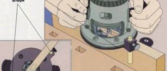
Quite often, among owners of poorly functioning or already faulty office equipment, the question comes up about what can be done from an old printer. Of course, the easiest way to solve this problem is to send a used inkjet or laser printer to. But if you have free time and some desire, then you can turn a printer into a CNC machine, i.e. equipment with numerical control, which has found wide application for solving both amateur and professional problems. You can find out about this in more detail below, but first, let’s look at the question of what can be extracted from an old printing device.
Retrieving future spare parts
So, if your printer (whether inkjet or laser) has already broken down or its service life is coming to an end, then do not rush to throw it away. The fact is that it is best to disassemble old office equipment into spare parts, which can later be used to repair new printers. Multifunctional devices and devices that use matrix printing technology are best suited for analysis, because from them you can get a lot of useful things for those who want to make a CNC machine with their own hands.
- First of all, disassemble the old device into parts, and all the nuts, screws and screws may be necessary in the future, so do not throw them away, but put them in some box and put them aside. Moreover, many often have to face a situation where they do not have the necessary nut at hand.
- One of the most valuable parts in any printing device is the hardened steel guide. This is especially true for older model printers, the guides of which are very difficult to bend. But in some 3D printers they often skimp on these parts, as a result of which the guides in them can bend even under the pressure of a tensioned drive belt. High-quality and reliable steel guides are perfect for machine tools, so feel free to remove a part of this kind from your device.
- Along with the above-mentioned part comes the so-called device head sliding unit. For inkjet printers, a similar part is made of plastic, as a result of which it is only suitable for unloaded axes of CNC engravers - be sure to take this into account! As for old matrix-type devices, their assembly contains a bronze bushing - a part of this type can be safely used on homemade equipment with numerical control, which will be used for processing plastics and non-ferrous metals.
- Another important part that can be used to make a machine is a toothed drive belt. It is worth noting that a part of this kind is available in both the old copier and the laser MFP.
- Also, be sure to remove the stepper motors that are used to move the machine head and move the paper. A matrix device usually has a more powerful stepper motor than other types of printers. From an MFP that uses laser printing, you can take out a stepper, which is quite suitable for the production of a numerically controlled router, which will be used in domestic conditions.
- Along with the stepper, do not forget to also remove the controller that controls it.
- Another great device that can be used as a spare part is limit switches. In printing office equipment, they are designed to control whether there is paper in the device or not. Such switches are divided into automatic and mechanical type devices.
How to make a mini drill from an old printer motor
After disassembling the printer, many useful parts remained, including several electric motors.
It's time to make a mini drill or mini drill. A package just arrived from Aliexpress with a quick-release chuck. Nowadays, making a homemade drill does not require much effort or material costs. To do this, you need to have an old inkjet printer; remove the power supply and the printer carriage motor from it. The power supply can be easily made adjustable.
Many inkjet printers use the same type of carriage motors. They are designed for DC power supply with a voltage of 24 V.
List of tools and materials. — DC electric motor - 1 piece; — jaw chuck - 1 piece; - connecting wires; — power switch - 1 piece; - a piece of plastic pipe; — caps from aerosol cans - 2 pcs; - screws; — 24 V power supply; - soldering iron; - tester. Step one
. Installing the jaw chuck. We put the chuck adapter on the electric motor shaft, then with light blows, preferably with a wooden hammer or a spacer (so as not to damage the thread), firmly put the adapter in place. If the shaft fits completely into the adapter, there will be no beating. All that remains is to fix the adapter on the motor shaft using a wrench with two screws.
Step two.
Power supply and operation check.
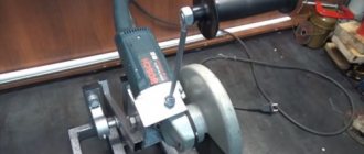
To power the mini drill, I used a power supply removed from the same printer. The circuit was slightly changed and a control voltmeter and trimming resistor were added to change the voltage. As a result, we get the opportunity to regulate the speed of the mini drill by changing the output voltage of the power supply. Small tests of the drill were carried out. Drills through printed circuit boards with ease. There is no chuck runout.
Using an attachment with sandpaper, I cleaned the old rusty tool.
The cutting wheel quickly cut off a piece of plastic. The heating of the electric motor during operation is minimal; the current consumption at a supply voltage of 24 Volts was a maximum of 0.3 A.
Step three
. Final assembly. All that remains is to install the mini drill in a suitable housing, connect the connecting wires and the power switch. I selected a piece of plastic pipe suitable for the diameter of the electric motor for the tool body. The engine fits tightly into it. Caps from aerosol cans were used as front and back covers. In the front cover we drill a hole for the central part of the engine and two holes for securing the engine housing with screws.
In the back cap we drill holes for the power switch and wires.
Both caps are attached to the plastic pipe with screws.
The tool is now finally ready for use.
In the video you can watch the process of manufacturing and testing a mini drill for performing small jobs.
Summary:
1. The materials cost 120 rubles (cartridge), the power supply is free from the printer (the same power supply can be used to power other homemade products). 2. The time spent assembling the tool was approximately 2 hours. 3. Lightweight and quite useful tool for small household work. 4. The pleasure of making a useful homemade product with your own hands.
Become the author of the site, publish your own articles, descriptions of homemade products and pay for the text. Read more here.
Video text
TRentMe.com – Rental company in Bulgaria: car rental, real estate, car selection e-mail:
In this video, I will disassemble the printer, show you and tell you what useful things can be learned from it. I will also show which motor can be used for mini drills. —How to make a mini-drill from parts of the printer: https://www.youtube.com/watch?v=_j_uV. Join the VKontakte group https://vk.com/samo_delkini Facebook ttps://www.facebook.com/groups/362989353894627/ Publish your videos, links, diagrams, ideas, discuss interesting topics with friends. Support and share with friends! I will be very grateful. In this video, I make out the printer, show and tell, what good can be extracted from it. Also show which of the engines can be used for mini drills.
If you have any other questions or suggestions, write in the comments under this video, I will try to help. Or write to me by email in the “About the channel” section on the channel’s main page, we can discuss private questions and advise on other related topics. If you still have questions or suggestions, please write in the comments under this video, I will try to help you. Or write me an email in the “Channel Info” link on the main page, we can discuss private matters and to consult on other related topics.
Product details
As a rule, only one element in a scanner or laser printer becomes unusable, while the rest of the parts are quite usable. The most valuable in this sense are MFPs and matrix devices. When disassembling the latter with your own hands, you can get a lot of valuable parts.
Old printer
- Fasteners - screws, nuts, gears, bolts and other small items. For the home craftsman, any fastener is useful, since sometimes the lack of elements of the required diameter makes work very difficult.
- The most valuable part in any type of printer is the guide, made of hardened steel. In many Chinese and Korean devices, the guide is made of cheap alloy and bends even under the weight of the drive belt. Inkjet devices from Canon or Epson use steel. This part is used in the construction of CNC machines or homemade printing devices.
- The head sliding unit - in inkjet devices it is plastic and is only suitable for CNC engravers, but in matrix engravers a bronze bushing is pressed into the unit, so the part can be used on metalworking home machines.
- If you intend to install a printing device, a Canon cartridge is the best option.
Cartridge from Canon
- A toothed drive belt is a universal element suitable for any device where it is necessary to transmit force from a stepper motor to a platform. And the belt sliding assembly can be found in MFPs and scanners and even old copiers from Epson.
- Stepper motor – provides the movement of the paper. On older dot matrix and laser devices they are more powerful, however, and the parts of inkjet printers can be used effectively. In addition, the engine along with the controller and driver can be removed from the old machine.
- Limit switches – provide control over paper quality. A necessary part for a homemade printing device or machine.
Limit switches
The cartridge is filled with special ink.
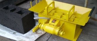
The photo shows a modified old printer.
Wind generator from an electric motor
What else can you do with your old printer? A wind generator that converts wind power into electricity. Such a device may well provide for household needs. In essence, this is not the use of the entire device, but only parts. Stepper motors from a laser device or MFP are preferable.
- The old printer is disassembled to remove the stepper motor.
- Assemble the rectifier: 2 diodes are required for each of the 4 phases.
- The blades are made from PVC pipe - this makes it easier to select the desired degree of curvature.
- The bushing with slate is machined to the size of the shaft.
- The sleeve is placed on the shaft, secured, and the blades are fixed to the flange. It is important to balance the composition.
- The motor is inserted into a piece of pipe where it is secured with bolts. A duralumin weather vane is fixed to the pipe from the end. The entire structure is supported by a vertical pipe.
The video demonstrates how to assemble a wind generator with your own hands.
Assembling a CNC machine
We cut out two squares of plywood with our own hands measuring 370 x 370 mm for the side walls, one 340 x 370 mm for the back and one 90 x 340 mm for the front wall. The walls of the CNC machine are fastened with your own hands using self-tapping screws through holes made in advance with a drill with a distance to the edge of 6 mm. The guides along the Y-axis are duralumin corners. To attach them to the side walls, a 2 mm tongue is made 30 mm from the bottom of the body. Thanks to the tongue and groove, the guides are installed evenly and do not warp. The corners are screwed through the central surface with self-tapping screws. The length of the guides is 340 mm. Such guides last up to 350 hours of operation, after which they need to be replaced. The working surface is made from corners 140 mm long. One 608 bearing is bolted to the bottom and two to the top.
It is important to maintain alignment so that the tabletop moves without stress or distortion. An outlet for the Y-axis motor with a diameter of 22 millimeters is made 50 mm from the bottom. For the propeller support bearing, a 7 mm hole is drilled in the front wall. We will make the propeller with our own hands from a stored construction pin; it interacts with the motor through a homemade coupling (details on manufacturing below). Screw holes with a diameter of 2.5 millimeters with an M3 thread are made in the extended M8 nut. The nut will be screwed onto the axle. We will make the X-axis from steel guides, which are found in the printer body
The carriages that are put on the axles are also taken there. You will have to tinker with making the Z-axis. Its base is made of No. 6 plywood. We remove the guides with a diameter of 8 mm from the printer. The plywood elements are fixed together with PVA glue, into which linear bearings are glued onto epoxy resin or the bushings are removed from the carriages. Let's make another running nut using the already known algorithm. Instead of a spindle, the CNC machine will have a Dremel with a holder made from a board bracket. A hole with a diameter of 19 millimeters is made from below for the Dremel to exit. The bracket is fixed with self-tapping screws to the base of the Z-axis in pre-prepared holes. The support for the Z-axis carriage is made of plywood: the base is 15 x 9 cm, the bottom and top sides are 9 x 5 cm. A hole is made in the middle of the top for the support bearing. Exits are also drilled for the guides. The final step is to assemble the Z-axis with the Dremel bracket and install it into the machine body.
The nut will be screwed onto the axle. We will make the X-axis from steel guides, which are found in the printer body. The carriages that are put on the axles are also taken there. You will have to tinker with making the Z-axis. Its base is made of No. 6 plywood. We remove the guides with a diameter of 8 mm from the printer. The plywood elements are fixed together with PVA glue, into which linear bearings are glued onto epoxy resin or the bushings are removed from the carriages. Let's make another running nut using the already known algorithm. Instead of a spindle, the CNC machine will have a Dremel with a holder made from a board bracket. A hole with a diameter of 19 millimeters is made from below for the Dremel to exit. The bracket is fixed with self-tapping screws to the base of the Z-axis in pre-prepared holes. The support for the Z-axis carriage is made of plywood: the base is 15 x 9 cm, the bottom and top sides are 9 x 5 cm. A hole is made in the middle of the top for the support bearing. Exits are also drilled for the guides. The final step is to assemble the Z-axis with the Dremel bracket and install it into the machine body.
Making a coupling
The clutch dampens vibration coming from the propeller. This allows you to save the bearings of the stepper motor and extend its life. In addition, a homemade clutch eliminates the discrepancy between the axes of the propeller and the motor.
The most convenient and easiest way to make a coupling with your own hands is to use a durable rubber hose. Select a hose with a diameter inside equal to the diameter of the motor axis. We put the end of the hose on the motor pulley and glue it or secure it with a coupling. We also attach the other end of the hose to the stroke screw. As a rule, the diameter of the screw is larger than the internal diameter of the hose. But thanks to the thick walls, it can be drilled out a little. Liquid soap makes the work easier, as it prevents the drill from getting stuck in the rubber.
The second method is a little more complicated: instead of a rubber hose, we take a gas hose with a rubber braid with our own hands. The braid can be carefully soldered onto the flanges into which the lead screw and motor pulley will be inserted.
And the most practical option: install flanges on a high-pressure rubber tube. In this way, you can very tightly fix all the necessary devices; a homemade coupling perfectly damps vibration. Flanges can be made on a CNC lathe or ordered from a workshop.
Creating a homemade machine
Before converting printers or scanners into mini machines that can perform milling work, you should assemble the structure frame and its main components as accurately as possible.
The top cover of the device requires installation of the main axes, which are important components among all professional machines. There should be only three axes; work must begin by fastening the y-axis. In order to create a guide, a furniture runner is used.
Separately, we note the creation of a CNC from a scanner. Remaking this device is the same as if you had an old inkjet printer at hand. In any scanner, there are stepper motors and pins, thanks to which the scanning process is carried out. In the machine, these motors and pins will be useful to us; instead of scanning and printing, milling will be done, and instead of a head that moves in the printer, the movement of the milling device will be used.
For the vertical axis, in a homemade CNC, we will need parts from the disk drive (the guide along which the laser moved).
Printers have so-called rods, they play the role of lead screws.
The motor shaft must be connected to the stud using a flexible coupling. All axles must be attached to bases made of chipboard. In structures of this type, the milling cutter moves exclusively in the vertical plane, while the part itself shifts horizontally.
Stepper motor from an old printer as a generator
Having disassembled the old printer, I got this beauty:
What is this? Stepper motor, there are plenty of motors of this type in printers and CD/DVD drives and in old floppies.
What can it be useful for, you ask? They make excellent alternators (thanks Tesla), and AC can be converted to DC without any problems. And what’s most interesting is that the alternating current during rectification can be multiplied using a voltage multiplier, ChipiDip will tell you about them:
I assembled a voltage doubler according to the classical circuit and connected it to one phase of the motor:
Capacitors of 10,000 uF are more than enough for the robot with my stepper.
Schottky diodes have a slightly higher efficiency than conventional silicon diodes, so I settled on them. My diodes are designed for a current of 5 Amps, so I’m not afraid of burning them.
I spun it a few times by hand and...
Let's try to make a spark:
The accumulated energy in the capacitors was even enough for two.
The voltage went above 20 volts, but you should not think that above 20 volts is already a lot, as you can see, the energy accumulated in the capacitors slightly spun up the computer cooler. As they taught in school, power (measured in Watts) is voltage multiplied by current, and the current is small, which can be seen in the video below:
The power obtained by hand may be small, but the cooler spins a little faster than through a conventional bridge rectifier, and you can also assemble another doubler and connect it to the second free phase and by connecting it in series or in parallel you can double the current or voltage.
My channel is on YouTube, subscribe, it will be more interesting.
Source
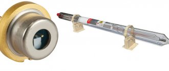
How does the laser work in a laser printer?
Color laser printers
Charged small particles of toner, consisting of coloring pigments, resins and polymers, are attracted to the discharged areas of the drum surface. Next, the toner from the photodrum is transferred to a transfer belt, on which a full-color image is formed, and from which the toner is transferred to paper.
Interesting materials:
How to change caps in text? How to change a fan on a video card? How to change Windows 10 to 8? How to change age in PS4? How to wash a fan? How to understand pure Android? How to understand that the BIOS has crashed? How do you know if your Dualshock 3 is charged? How to understand that the PS3 joystick is charging? How to understand that the PS4 joystick is charging?
DIY CNC machine from a printer
You will also need regular tools such as a drill, drill bits, screwdriver and others.
Step 1: Find an Old Printer or Scanner
To make a homemade CNC machine from a printer, you first need to stock up on the necessary materials. This stage is the most enjoyable in the process of assembling a machine, since it represents attempts to find the junk that people want to get rid of. You can use your own materials or buy them. But if you want to reduce machine costs as much as possible, the best option would be a CNC from an old printer. Here are the items you need to find:
- Flatbed scanner
- Old printer
These devices have great stepper motors, amazing rods made from hardened steel, and more.
You will also find gears, bushings, cold cathodes, capacitors, buttons, parallel ports and much more.
Step 2: Tools
During assembly, only all the essentials were used to show that you can assemble a CNC machine from a printer with your own hands, having a minimal set of tools.
- Drill
- Screwdriver Set
- Set of taps and dies
- Multifunctional tool
- Hacksaw for metal
- Machine vise or other clamping device
- Pliers
- Drill
- File
- Kerner
- Band-saw
- Circular machine
- Lathe
- Bench Grinder
- Bolt cutter
Step 3: Linear Guides
The center of your CNC printer is its desktop, so read this article carefully and follow the instructions
This is just a list of the essentials.
As you can see, to assemble a CNC from an old printer with your own hands, you need simple, readily available and inexpensive tools. Almost everyone has similar materials in stock, but you can purchase them at any store for little money.
Lay two equally sized pieces of PVC foam on top of each other and drill a hole in the center, and two more holes each 3/4 inch from the center line (from the edge).
Now cut the aluminum rods to size and insert them into the drilled holes - you should end up with parts similar to those shown below. The CNC machine from the printer is almost ready!
Repeat the above procedure for each axis.
Step 4: guide plates along the X, Y, Z axes
So, we move on to the most material-intensive stage of work - the production of guide plates. Once they are completed, there is a real sense that the project has begun to move forward.
Now you need to place 4 sheets of plexiglass measuring 38x44x12 mm on top of each other and drill a hole in them exactly in the center using a 9.5 mm drill.
After completing the above procedure, push the pieces of plastic placed on the rods (2 pieces on each rod) to the desired locations and align them, then place the sheets on top. Then turn the structure over and glue them.
Repeat the procedure for each axis.
Now is the time to drill the holes necessary to fix the workpieces during processing on the planned CNC from the printer.
Step 5: installing the electric motor
Depending on which electric motor you have, you will need different mounts to install it, since they are all different from each other.
It is advisable to use stepper motors from printers due to their ease of installation, but motors from scanners will also work well.
In step three you should have drilled the holes to install the motor and now all you have to do is secure it.
Selecting the appropriate type of coupler that connects the stepper motor to the threaded rod depends on the type of motor you have at your disposal.
In this case, an elongated nut was used as a connector, but you can make it from plastic - the main thing is that it is of sufficient size.
All you have to do is drill a hole in the center of the rod on the motor side that matches the diameter of the stepper motor shaft, then drill an 8mm hole for the threaded rod on the other side.
After this, cut a thread on the side on which there is a hole with a diameter of 8 mm and glue the parts together.
Step 6: Making the carving
Once you've installed the nut, it's time to secure the threaded rod and glue the nut to one of the 38x44x12mm rectangular plates.
Make sure that the center of the threaded nut is aligned with the center of the threaded rod.
After completing this procedure, you should have a knot similar to the one shown below.
Breadbox or minibar
Given enough time, almost any old printer can be converted into some interesting things. For example, after completely clearing the printer of all unnecessary parts, the resulting form must be covered with fabric. A small convenient space can be used at personal discretion, like a mini-bar, or even a bread bin. It will also work as a good hiding place.
More skilled people will be able to even make a CNC machine from an ordinary cheap inkjet printing device. The device must be disassembled into its components. Among the valuable and necessary parts we select a hardened steel guide; the set includes a toothed drive belt, as well as a printer head sliding unit, along with stepper motors. The set also includes limit switches, in the manufacture of CNC machines, to limit failure and damage. From the received components you can see that there are almost all the necessary parts to assemble a CNC machine.
There is one more remarkable detail in the printer - a board with high-voltage converters. It is worth noting that the procedure is very dangerous. You will need knowledge in electronics, otherwise you should not put yourself in danger. However, in the end we get a nice shocker keychain.
Printers have powerful motors to which you can attach blades and generate electricity, for example in a country house.
It is important to remember to be careful when constructing such devices. These and many other ideas exist for old devices, like a printer, that are easy to adapt.
Lately I've been looking for ways to make PCB manufacturing easier. About a year ago, I came across an interesting page that described the process of modifying an Epson inkjet printer for printing on thick materials, including. on copper textolite. The article described the modification of the Epson C84 printer, however, I had an Epson C86 printer, but because... I think the mechanics of Epson printers are similar for everyone, so I decided to try to upgrade my printer.
In this article I will try to describe in as much detail as possible, step by step, the process of upgrading a printer for printing on copper-bonded PCB.
Necessary materials:
- Well, of course you will need the Epson C80 family printer itself. - a sheet of aluminum or steel material - staples, bolts, nuts, washers - a small piece of plywood - epoxy or superglue - ink (more on this later)
Tools:
- a grinder (Dremel, etc.) with a cutting wheel (you can try with a little monkey) - various screwdrivers, wrenches, hexagons - a drill - a hot air gun
Step 1. Disassemble the printer
The first thing I did was remove the rear paper output tray. After this, you need to remove the front tray, side panels and then the main body.
The photographs below show the detailed process of disassembling the printer:
Step 2. Remove the internal parts of the printer
After the printer body is removed, it is necessary to remove some internal parts of the printer. First, you need to remove the paper feed sensor. We will need it later, so do not damage it when removing it.
Then, it is necessary to remove the central pressure rollers, because they may interfere with the feeding of the PCB. In principle, the side rollers can also be removed.
Finally, you need to remove the print head cleaning mechanism. The mechanism is held on by latches and can be removed very easily, but when removing, be very careful, because different tubes fit to it.
The printer disassembly is complete. Now let's start “lifting” it.
Step 3: Removing the print head platform
We begin the process of upgrading the printer. The work requires accuracy and the use of protective equipment (you need to protect your eyes!).
First you need to unscrew the rail, which is fastened with two bolts (see photo above). Unscrewed? We put it aside; we will need it later.
Now notice the 2 bolts near the head cleaning mechanism. We also unscrew them. However, on the left side it is done a little differently; the fasteners can be cut off there. To remove the entire platform with the head, first, carefully inspect everything and mark with a marker the places where you will need to cut the metal. And then carefully cut the metal with a hand grinder (Dremel, etc.)
Step 4: Clean the print head
This step is optional, but since you have completely disassembled the printer, it is better to clean the print head right away. Moreover, there is nothing complicated about it. For this purpose I used regular ear sticks and glass cleaner.
Step 5: Install the print head platform. Part 1
After everything has been disassembled and cleaned, it is time to assemble the printer, taking into account the required clearance for printing on the PCB. Or, as jeepers say, “lifting” (i.e. lifting). The amount of lifting depends entirely on the material you are going to print on. In my modification of the printer, I planned to use a steel material feeder with a PCB attached to it. The thickness of the platform for supplying material (steel) was 1.5 mm, the thickness of the foil PCB, from which I usually made boards, was also 1.5 mm. However, I decided that the head should not press hard on the material, and therefore I chose a gap size of about 9 mm. Moreover, sometimes I print on double-sided PCB, which is slightly thicker than single-sided.
To make it easier for me to control the level of lift, I decided to use washers and nuts, the thickness of which I measured with a caliper. I also bought some long bolts and nuts for them. I started with the front feed system.
Step 6: Install the print head platform. Part 2
Before installing the print head platform, it is necessary to make small jumpers. I made them from corners that I sawed into 2 parts (see photo above). You can of course make them yourself.
Afterwards, I marked the holes for drilling in the printer. The bottom holes are very easy to mark and drill. Then, I immediately screwed the brackets into place.
The next step is to mark and drill the upper holes in the platform; this is somewhat more difficult to do, because everything should be on the same level. To do this, I placed a pair of nuts in the places where the platform joins the base of the printer. Using a level, make sure the platform is level. We mark the holes, drill and tighten with bolts.
Step 7. “Lifting” the print head cleaning mechanism
When the printer finishes printing, the head is “parked” in the head cleaning mechanism, where the head nozzles are cleaned to prevent them from drying out and clogging. This mechanism also needs to be raised a little.
I secured this mechanism using two corners (see photo above).
Step 8: Feed System
At this stage, we will consider the process of manufacturing the feed system and installing the material feed sensor.
When designing the feed system, the first challenge was installing the material feed sensor. Without this sensor the printer would not function, but where and how to install it? When paper passes through the printer, this sensor tells the printer controller when the beginning of the paper has passed and based on this data the printer calculates the exact position of the paper. The feed sensor is a conventional photosensor with an emitting diode. When paper passes (in our case, material), the beam in the sensor is interrupted. For the sensor and feed system, I decided to make a platform out of plywood.
As you can see in the photo above, I glued several layers of plywood together in order to make the feed flush with the printer. In the far corner of the platform I attached a feed sensor through which the material will flow. I made a small cutout in the plywood to insert the sensor.
The next task was the need to make guides. To do this, I used aluminum corners, which I glued to the plywood. It is important that all angles are clearly 90 degrees and the guides are strictly parallel to each other. As the feed material, I used an aluminum sheet on which the copper-plated PCB will be placed and fixed for printing.
I made the material supply sheet from an aluminum sheet. I tried to make the sheet size approximately equal to A4 format. After reading a little on the Internet about the operation of the paper feed sensor and the printer in general, I found out that for the printer to work correctly, it is necessary to make a small cutout in the corner of the material feed sheet so that the sensor is triggered a little later than the feed rollers begin to spin. The length of the cutout was about 90mm.
After everything was done, I attached a regular sheet of paper to the feed sheet, installed all the drivers on the computer and made a test print on a regular sheet.
Step 9. Filling the ink cartridge
The last part of the printer modification is dedicated to ink. Regular Epson ink is not resistant to the chemical processes that occur during etching of a printed circuit board. Therefore, you need special ink, they are called Mis Pro yellow ink. However, this ink may not be suitable for other printers (non-Epson), because... other types of printheads may be used there (Epson uses a piezoelectric printhead). The online store inksupply.com offers delivery to Russia.
In addition to ink, I bought new cartridges, although of course you can use old ones if you wash them well. Naturally, to refill the cartridges you will also need a regular syringe. Also, I bought a special device for resetting printer cartridges (blue in the photo).
Step 10. Tests
Now let's move on to printing tests. In the design program, I made several blanks for printing, with tracks of different thicknesses.
You can evaluate the quality of printing from the photographs above. And below is a video of printing:
Step 11: Etching
For etching boards manufactured using this method, only a ferric chloride solution is suitable. Other etching methods (copper sulfate, hydrochloric acid, etc.) may corrode Mis Pro yellow ink. When etching with ferric chloride, it is better to heat the printed circuit board using a heat gun, this speeds up the etching process, etc. Less “eating” of the ink layer.
The heating temperature, proportions and duration of etching are selected experimentally.
By placing the moving mechanisms that move the head in the CD/DVD drive at an angle of 90, we get an XY platform with a very small construction area, but with very high positioning accuracy. Using laser head positioning from the CD drive mechanism to build a high-precision XY platform is not a new idea : builders.reprap.org/2010/08/selective-laser-sintering-part-8.html
Step 5: Assembling the XY Platform from Used Ear CD Drives
First, we collect a stack of old drives.
Open the tray using a paper clip. You may have to try several drives before you find one with a stepper motor. At least half of the ones we took apart had a DC motor. If anyone knows how to tell them apart by appearance, please let us know. They can be easily distinguished from each other by disassembling the drive: DC has two wires, and Stepper 4 and a short cable.
Unlike DC, stepper motors are designed to move a specific number of steps, with each step representing part of a full revolution. This makes it convenient for high-precision positioning, without the need to create a feedback system that checks the position of the head. For example, 3D printers typically use stepper motors to position the print head.
After checking some serial numbers online, we came across a well-documented bipolar stepper motor labeled PL15S-020. The other engines found are very similar to it, so they probably have the same parameters.
Technical data: robocup.idi.ntnu.no/wiki/images/c/c6/PL15S020.pdf
This stepper motor takes 20 steps per revolution (not a lot, but enough), and the lead screw has a step of 3 mm per revolution. Thus, each step is equal to 150 microns of movement of the laser head - not bad! On the Arduino.cc website we found circuits for bipolar stepper motors, as well as example code for controlling them. We ordered several SN754410NE H-bridges to implement the circuit shown in the last picture.
Old CD/DVD drives have many other interesting components! Including the opening/closing mechanism tray containing a low-speed gear DC motor, the spindle motor that rotates the CD is generally a high-performance brushless DC motor, which can be used in toy airplanes and helicopters. Plus, a bunch of switches, potentiometers, damn lasers, and even solenoids! In general, extract everything!!!
Step 6: Put it all together
Materials:
— Two mechanisms for moving the laser head with stepper motors (preferably identical) from old drives. Cost: a few dollars each. — One InkShield kit, with cartridge and cartridge holder. Cost: $57 - Optional: optional HP C6602 ink cartridge. Cost: $17 – Arduino Uno. Cost: $30 - Two SN754410NE H-Bridge Motor. Cost: $5 – Arduino prototyping kit and/or tiny breadboard. Cost: $4-21 - Wires, screws, stands, housings. Cost: from free to $$$, depending on your imagination.
Total production costs were about $150, including shipping and handling costs. The photo above shows two different models. The second version has a top plate made of high-quality acrylic and large internal space.
The CD drive's moving mechanism, located at the bottom, moves the blue plate on which you print something (for example, an agarose plate). The top drive mechanism, mounted at right angles, moves the inkjet print head. We used Shapelock and some screws to secure the bottom platform to the laser head, and secure the cartridge holder to the top laser head. The electronics consist of an Arduino Uno on the bottom, a white InkShield (connected to an inkjet cartridge holder with a nice white ribbon cable), and a protoboard with stepper motors on top.
Checkered paper strips on the lower and upper platforms allow us to track the position along the X and Y axes. The total print area is approximately 1.5 inches in both directions, with a resolution of 150 microns per step. It should be noted that the resolution of stepper motors is similar to the resolution of the print head: 96 dpi 265 micron pitch, but the dots printed by the print head are clearly separated - more like 150-200 microns.
Step 7: Success
This is our first truly working Bioprinter
. We refilled the E. coli liquid culture cartridge + pGLO. Slightly modified “I As you can see, printing with live E.coli cells works great! We probably let the bacteria colony take longer to develop, so the letters are a little blurry. We got small colonies spraying into the corners of the cell - probably due to some spraying from the jet head. We can improve quality by adjusting the viscosity or density of the culture cells loaded into the cartridge. But overall, not bad for the first time! After printing, we sanitized the surface and inside of the cartridge with bleach, and then ran some bleach through the head. Then we washed everything with distilled water. It would probably be a good idea to invest in an ultrasonic jewelry cleaner, which can also break down organic matter in the most difficult to reach places.
Step 8: Lesson Learned and Future Plans
We approached this project with virtually zero experience with Bioprinting, stepper motors, inkjet cartridges, or even Arduino programming!
Therefore, naturally, not all of our actions were optimal. Here are some things we could do differently next time: Learning how stepper motors work gave us some really valuable experience, but we could save a lot of time and effort by adapting some of the RAMPS (RepRap Arduino MEGA Pololu Shield) technology that was already good developed precisely for this purpose in the 3D printing community. In particular, the Pololu stepper motor already had built-in microstepping capabilities.
Building your own XY platform is great! But we're using these stepper motors for things they were never intended for, which is starting to show itself. We're already getting some issues with the bottom stage sometimes skipping, apparently due to frequent manual resets wearing out the plastic parts. It was easy enough to buy new stepper motors to hold them, add some microswitches for the end stops, and code the position reset function in the software.
Once you start looking for new stepper motors and RAMPS electronics, the question becomes why not start straight away with 3D printers instead? If we are tired of our current version of the bioprinter, it is probably because of the chosen direction. The cost will most likely increase by an order of magnitude anyway, although...
Having one print head has its limitations. If we really wanted to do some kind of tissue engineering, we would like to be able to print multiple types of cells. We could potentially put two ink cartridges next to each other. The Big Boys' solution in this area is the use of syringe pumps. Imagine having several syringe pumps next to a printer, each delivering its own print material through a thin tube, with needles mounted on the print head. Stay tuned…
Now it's a bull in a china shop... What the hell are you doing with your own bioprinter?! I don't think BioCurious will ever compete with companies like Organovo in terms of printing human tissue or organs. On the one hand, maintaining animal cells takes much more effort. Plant cells are much easier to work with! I don't want things to go to waste, so keep an eye out for some of our next tutorials!
In the meantime, here are some ideas:
Print gradients of nutrients and/or antibiotics onto a layer of cells to study combinatorial interactions—or even to select different isolates from an environmental sample. — Printing growth factor patterns onto a layer of eukaryotic cells to study cell differentiation. — Printing two or more types of microorganisms at different distances from each other to study metabolic interactions. — Setting up a computational task as a 2D model of the construction of a microorganism on an agar plate. — Study of reaction-diffusion systems — Printing 3D structures using repeated printing of layers. Now you can consider making everything taller in 3D! — Print cells in a sodium alginate solution, on a surface impregnated with calcium chloride, to create 3D gel structures (similar to the spherification process in molecular gastronomy)
Any other ideas? Leave them in the comments!
Step 9: Added: So what do you want to do for real science?
The bioprinter shown here is obviously just a prototype.
But since we've had very serious requests for using this in academic labs, here are some recommendations: Dolphin Dean's group at Clemson University is working on Bioprinting using a modified HP DeskJet 500. Definitely check out their video on JoVE on Creating Transient Cell Membrane Pores Using a Standard Inkjet Printer! Loads of information on how to deal with inkjet printers used as laboratory equipment, how to clean cartridges, prepare appropriate cell suspensions, and some intriguing non-3D printing applications.
We have not yet received satisfactory evidence that HP C6602 cartridges can print eukaryotic cells. We believe that this is most likely due to the print head being clogged with cell breakdown products. We will keep you updated on the use of ultrasonic cleaning machines...
- old iron
Add tags
Reusing equipment, objects, decorations, things is far from a sign of limited funds. Rather, it is an opportunity to show skill, intelligence and prevent the occurrence of waste. Equipment such as scanners, inkjet and laser printers do not wear out very quickly, but they become obsolete soon. This means there is no way to find parts for repair.
Numerous forums will tell you what to do with such devices.
What will we talk about:
How to assemble a mini drill from a printer motor
To assemble a mini-drill, you still have to buy some parts. But they will cost you pennies, and you can find them in an electronics store.
The first is a nozzle of this type. It should fit the motor, so go buy it with it. The attachment is fixed on the rotating part with a pair of bolts, and you can connect anything you want to it: from a drill to a knife or a cutting wheel. Dremel attachments are sold in sets and individually
The second necessary part for the device is a tiny switch that you install on the drill to control rotation. The switch will be mounted in the body of a regular plastic bottle cap; to do this, you need to cut a hole in it corresponding to the size of the switch.
You need to make another hole in the plastic cover through which the power wire will be threaded.
Pass the wire, solder one end to the motor, and make the second contact with a gap into which you will then insert the switch. Secure the plug itself to the motor with hot glue
Even if you have a mini drill, do not forget about safety precautions. With such miniature tools, you can, for example, engrave on glass, and this is fraught with injury from small fragments. To protect your eyes, you need to make a protection on the body of the instrument, which will prevent the scattering of fragments and other particles.
Such protection can be made from an ordinary plastic bottle. Cut a piece together with the neck approximately 6 cm long
Cut out a part of approximately this configuration. Lightly heat the edges with a lighter so that they melt and become stronger.
Place several neodymium magnets inside the neck using good glue.
The protection is very easy to put on and is held in place by the force of magnets on the case, protecting you from flying debris. Choose a transparent bottle for protection so you can see the working tool
Cover the drill body together with the plug with heat shrink. To do this, place the motor in the heat shrink tube and simply heat it over the burner
Now you can connect the switch. Pull the ends of the wire through the hole in the plug and solder it to the switch contacts. Then put it in its place
Necessary materials
So for manufacturing we will need the following units:
- Material for making the case. You can use wood boards, such as MDF, chipboard; from wood boards, I would optimally recommend using plywood, as it is the most durable and rigid. If you want to be even more reliable, you will have to make the structure out of metal;
- Spindle. For wood processing, a power of 1.3 - 2 kW is suitable. If you do not want to cool the machine every 15 minutes of operation, then the spindle must be installed with water cooling;
- Frequency generator, also known as frequency converter, also known as inverter. Selected with the same power as the spindle power;
- Control board;
- Stepper motors - 3 pieces, one will move our structure along the Y axis, the other along the X axis, the third along the Z axis.
- Cable channel to protect the cable from damage and breakage, since the equipment will move a lot;
- The cable is 15 - 20 meters, it is better to calculate everything in the drawing;
- A collet for a spindle is another name for a chuck for a milling cutter;
- Cooling hose;
- Bearings;
- Soft clutch for smooth running and compensation of stepper motor alignment;
- Of course, cutters for wood processing;
- Screws and bolts;
- Water pump.
Step-by-step instruction
In order to understand where to start, let's focus on the CNC circuit diagram.
So, the assembly of the finished machine is carried out in the following sequence:
- Creation of drawings, taking into account the installation and connection of electrical equipment. You can draw by hand, but I would recommend programs such as Compass, AutoCAD or Visio. It will be easier to correct the drawing in them, and Visio even has ready-made libraries for electrical equipment;
- The next step is to order components;
- Once the components have arrived, you can begin installing the frame. Why after admission? Yes, in order to make a frame taking into account the components that have already arrived;
- Spindle installation;
- Installation of a water cooling system. During this operation, you will most likely have to use fume tape and ordinary automotive sealant in order to make the structure more reliable and not leak;
- Connecting electrical wiring, installing an emergency stop button;
- Connecting the control board (aka controller). As such a board you can use - KY-2012 - 5 Axis CNC Breakout Board for Stepper Motor Driver with DB25 Cable. It won’t be difficult to find one on the Internet. You can also often find homemade machines based on arduino;
- Installing software and downloading drawings;
- Setting up the machine or the so-called “commissioning”.
Blueprints
As I said above, when creating drawings it is necessary to draw all the details from dimensions to electrical wiring. This will reduce the number of errors in machine design.
We make a frame
As I already said, the frame can be made of either plywood or metal. You can combine the use of these materials. Below is a drawing of the frame.
Do not forget about the rigidity of the structure and its geometry
It is very important to leave adjustments for fine-tuning the machine:
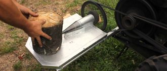
- The height of the car is as in the video;
- Along the X and Y axes.
This video will help you avoid making mistakes:
Spindle mounting
We install the spindle only after the frame is completely installed. During installation, it is necessary to leave the possibility of height and vertical adjustment on the spindle. In other words, if the spindle is not installed vertically, an adjustment is needed to set the desired angle.
We assemble a CNC machine from a printer with our own hands
In order to make a CNC machine from a printer with your own hands, you will need the following available materials:
- spare parts from several printers (in particular the drive and pins);
- hard drive drive;
- several sheets of chipboard or plywood, furniture guides;
- controller and driver;
- fastening materials.
1. The base is a box made of chipboard. You can take a ready-made one or make it yourself. We immediately take into account that the internal capacity of the box must accommodate all the electronic filling, so the height of the side is calculated from the height of the board with parts, fastenings and reserve to the table surface. The base and frame are assembled from chipboard using self-tapping screws. In this case, all parts must be level and secured at right angles.
2. The machine axes must be secured to the base cover. There are three of them - xy z. First we attach the y axis. To make the guide, a furniture runner on ball bearings is used.
It is better to use two guides for two horizontal axes, otherwise the axes will have significant play. For the vertical axis, the role of the guide is played by the remains of the hard drive, the part where the laser moved.
The rod from the printer is used as a lead screw. In this case, threaded screws with a diameter of 8 mm are made for the horizontal x y axes. For the vertical z axis, a threaded screw with a diameter of 6 mm was used. Drives from old printers are used as a stepper motor. One drive per axle.
3. The pin is attached to the plane using a metal angle.
The motor shaft is connected to the stud through a flexible coupling. All three axes are attached to the base through a chipboard frame. In this design, the milling cutter will move only in the vertical plane, and the movement of the part is carried out due to the horizontal movement of the platform.
4. The electronic unit consists of a controller and a driver. The controller is made on Soviet K155TM7 microcircuits; for this case, three were used.
From each chip, wires go to the driver of each of the three motors. The driver is made on a transistor. The drive uses KT 315, transistors KT 814, KT 815. From these transistors, an electrical signal is supplied to the winding of the electric drive.
At normal operating voltage, motors may overheat due to the lack of busbars in the electronic unit. To prevent this, a computer cooler must be used for each engine.
Video: a simple DIY CNC machine for beginners.
Let's start production
To start making a CNC machine out of an old printer, you will need some parts that come with inkjet printers:
- Drives, pins, guides from the printer (it is advisable to use several old printers; the printers do not necessarily need to print);
- Drive from floppy drive.
- Material for creating the body - plywood, chipboard, etc.
- Drivers and controllers;
- Materials for fasteners.
The resulting numerically controlled machines will be able to perform various functions. Everything ultimately depends on the device that will be located at the output of the machine. Most often, inkjet printers are used to make a burner (by installing a burner at the output of the device) and drilling machines for creating printed circuit boards.
The basis is a wooden box made of chipboard. Sometimes they use ready-made ones, but it’s not difficult to make it yourself. It is necessary to take into account that electronic components and controllers will be located inside the box. It is best to assemble the entire structure using self-tapping screws. Do not forget that the parts must be positioned relative to each other at an angle of 90 degrees and fastened as firmly as possible to each other.
Electronic components of future machine tools
This is one of the most important design stages. The electronics of homemade machines is a key element in controlling all engines and the process itself.
The homemade machine can operate on domestic K155TM7, we need 3 of them.
Each driver has wiring from its own microcircuit (the controllers are independent).
Stepper motors in a homemade device must be designed for a voltage not exceeding 30-35 V. It often happened that with increased power, Soviet microcircuit controllers burned out.
The power supply is ideal for the scanner. It needs to be connected to the unit, to the power button, the controller and the device itself (milling cutter, drill, burner, and so on).
Plotting machines are devices that automatically draw drawings, pictures, diagrams on paper, fabric, leather and other materials with a given accuracy. Models of equipment with a cutting function are common. Making a plotter with your own hands at home is quite possible. To do this, you will need parts from an old printer or DVD drive, certain software and some other materials.
Making a small plotter from a DVD drive yourself is relatively simple. Such a device on Arduino
will cost much less than its branded counterpart.
For work you will need the following materials
:
- glue or double-sided tape;
- solder for soldering;
- wires for mounting jumpers;
- DVD drive (2 pcs.), from which the stepper motor is taken;
- Arduino uno;
- servo motor;
- microcircuit L293D (driver that controls motors) – 2 pcs.;
- solderless breadboard (plastic base with a set of electrically conductive connectors).
To bring your planned project to life, you should collect the following tools
:
- soldering iron;
- screwdriver;
- mini drill.
Experienced electronic DIY enthusiasts can use additional parts to assemble a more functional device.
Assembly steps
The assembly of the cnc plotter is carried out according to the following algorithm:
using a screwdriver, disassemble 2 DVD drives (the result is shown in the photo below) and take out the stepper motors from them, and from the remaining parts select two side bases for the future plotter;
Disassembled DVD drives
the selected bases are connected using screws (having previously adjusted them to size), thus obtaining the X and Y axes, as in the photo below;
XY axes in assembly
the Z axis is attached to the X axis, which is a servo drive with a holder for a pencil or pen, as shown in the photo;
attach to the Y axis a square measuring 5 by 5 cm made of plywood (or plastic, board), which will serve as the basis for the stacked paper;
Paper base
assemble, paying special attention to connecting stepper motors, an electrical circuit on a solderless board according to the diagram presented below;
Electrical connection diagram
- enter code to test the performance of the X-Y axes;
- check the functioning of the homemade product: if the stepper motors are working, then the parts are connected according to the diagram correctly;
- load the working code (for Arduino) into the CNC plotter made;
- download and run the exe program to work with G-code;
- install the Inkscape program (vector graphics editor) on your computer;
- install an add-on to it that allows you to convert G-code into images;
- configure the work of Inkscape.
After this, the homemade mini plotter is ready for use.
Some nuances of work
The coordinate axes must be located perpendicular to each other.
In this case, a pencil (or pen), fixed in the holder, should be able to move up and down without problems using a servo drive. If the stepper drives do not work, then you need to check whether they are connected correctly to the L293D chips and find a working option.
G-code is a file containing XYZ coordinates. Inkscape acts as an intermediary that allows you to create plotter-compatible files with this code, which is then converted into the movement of electric motors. To print the desired image or text, you will need to first convert it into G-code using the Inkscape program, which will then be sent for printing.
The following video demonstrates the operation of a homemade plotter from a DVD drive:
Electronic filling
There are two options:
- You arm yourself with a soldering iron, flux, solder, a magnifying glass, and understand the chips from the printer. Locate the 12F675 and LB1745 printer control boards. Work with them by creating a CNC control board. You will need to attach them to the back of the CNC machine, under the power supply (we also take it from the long-suffering printer).
- Use the factory CNC machine controller. Offhand – a five-axis CNC controller. Homemade electronics are wonderful, but the Chinese are heavily dumping on prices. So, with a light click of the mouse, we order the CNC from them, because in Russia you cannot buy such a CNC device. CNC controller 5 Axis CNC Breakout Board allows you to connect 3 inputs of limit motors, a shutdown button, automated control of a dremel and as many as 5 drivers for controlling a stepper motor of a homemade machine.
This CNC is powered by a USB cable. In a homemade version of the CNC, you need to power the control board based on printer chips from the power supply of the CNC machine.
A stepper motor for a homemade CNC machine will have to be selected with a power of up to 35 volts. At other powers, the CNC controller runs the risk of burning out.
Remove the power supply from the printer. Connect the wiring between the power supply, the on/off switch, the CNC controller and the Dremel.
Connect the wire from the laptop/PC to the machine control board. Otherwise, how will you load tasks into the machine? By the way, about assignments: download the Math3 program for drawing sketches. For non-industrial design professionals, CorelDraw will do.
You can cut plywood (up to 15 mm), textolite up to 3 mm, plastic, wood with a homemade CNC machine. The products will be no more than 30-32 cm in length.
Most people have equipment that is no longer working, or a device with severe technical damage. Naturally, such equipment is thrown away, but some people have a very working question: “What benefits can be obtained?” Even old devices can be used on the farm. In this article I wanted to talk about an ordinary printer.