Microprocessors work exclusively with digital signals: with a logical zero (0V) or with a logical one (5V or 3.3V). For this reason, the microprocessor cannot generate an intermediate voltage at the output. The use of external DACs to solve such problems is impractical due to their complexity. Pulse-width modulation has been developed specifically for this purpose - a certain process of controlling the power going to the load by changing the duty cycle of constant-frequency pulses.
What is a PWM regulator?
Now that we know what pulse width modulation is, we can talk about the main topic of the article. A PWM regulator is used to regulate the supply voltage and to prevent powerful inertial loads in automobiles and motorcycles. This may sound complicated and is best explained with an example. Let’s say you need to make the interior lighting lamps change their brightness not immediately, but gradually.
The same applies to side lights, car headlights or fans. This desire can be realized by installing a transistor voltage regulator (parametric or compensation). But with a large current, it will generate extremely high power and will require the installation of additional large radiators or an addition in the form of a forced cooling system using a small fan removed from the computer device. As you can see, this path entails many consequences that will need to be overcome.
The real salvation from this situation was the PWM regulator, which operates on powerful field-effect power transistors. They can switch high currents (up to 160 Amps) with only 12-15V gate voltage. It should be noted that the resistance of an open transistor is quite low, and thanks to this, the level of power dissipation can be significantly reduced.
To create your own PWM regulator, you will need a control circuit that can provide a voltage difference between the source and gate within the range of 12-15V. If this cannot be achieved, the channel resistance will greatly increase and the power dissipation will increase significantly. And this, in turn, can cause the transistor to overheat and fail.
A whole range of microcircuits for PWM regulators are produced that can withstand an increase in input voltage to a level of 25-30V, despite the fact that the power supply will be only 7-14V. This will allow the output transistor to be turned on in the circuit along with the common drain. This, in turn, is necessary to connect a load with a common minus. Examples include the following samples: L9610, L9611, U6080B ... U6084B. Most loads do not draw more than 10 amps of current, so they cannot cause voltage sags. And as a result, you can use simple circuits without modification in the form of an additional unit that will increase the voltage.
And it is precisely these samples of PWM regulators that will be discussed in the article. They can be built on the basis of an asymmetrical or standby multivibrator. It’s worth talking about the PWM engine speed controller. More on this later.
Reasons for the spread
What attracts car enthusiasts to a PWM controller? It should be noted that there is a desire to increase efficiency when constructing secondary power supplies for electronic equipment. Thanks to this property, this technology can also be found in the manufacture of computer monitors, displays in phones, laptops, tablets and similar equipment, and not just in cars. It should also be noted that this technology is significantly inexpensive when used. Also, if you decide not to buy, but to assemble a PWM controller yourself, you can save money when improving your own car.
Scheme No. 1
This PWM controller circuit was assembled using CMOS chip inverters.
It is a rectangular pulse generator that operates on 2 logic elements. Thanks to the diodes, the time constant of discharge and charge of the frequency-setting capacitor changes separately here. This allows you to change the duty cycle of the output pulses, and as a result, the value of the effective voltage that is on the load . In this circuit, it is possible to use any inverting CMOS elements, as well as NOR and AND. Examples include K176PU2, K561LN1, K561LA7, K561LE5. You can use other types, but before that you will have to think carefully about how to correctly group their inputs so that they can perform the assigned functionality. The advantages of the scheme are the accessibility and simplicity of the elements. Disadvantages: complexity (virtually impossibility) of modification and imperfection regarding changing the output voltage range.
The main problems of PWM converters
When operating any device, it is impossible to completely eliminate the possibility of breakdown, and this also applies to converters. The complexity of the design does not matter; even the well-known TL494 PWM controller can cause operational problems. Faults have a different nature - some of them can be detected by eye, while detection of others requires special measuring equipment.
To find out how to check a PWM controller, you should familiarize yourself with the list of main device malfunctions, and only later – with options for eliminating them.
Scheme No. 2
It has better characteristics than the first sample, but is more difficult to implement. Can regulate the effective load voltage in the range of 0-12V, to which it changes from an initial value of 8-12V. The maximum current depends on the type of field-effect transistor and can reach significant values. Considering that the output voltage is proportional to the control input, this circuit can be used as part of a control system (to maintain the temperature level)
Important Pages
- GyverKIT kit - a large Arduino starter kit of my design, sold in Russia
- Catalog of links to cheap Arduins, sensors, modules and other hardware from AliExpress from trusted sellers
- A selection of libraries for Arduino, the most interesting and useful, official and not so
- Complete documentation on the Arduino language, all built-in functions and macros, all available data types
- A collection of useful algorithms for writing sketches: code structure, timers, filters, data parsing
- Video lessons on Arduino programming from the “Arduino Engineer's Notes ” channel are some of the most detailed in RuNet
- Support the author for his work on the lessons
- Feedback - report an error in the lesson or suggest an addition to the text ( [email protected] )
4.8 / 5 ( 13 votes)
Pulse width control WID
In Western literature, there is practically no distinction between the concepts of pulse-width regulation of WID and pulse-width modulation of PWM. However, we still have a difference between them.
Nowadays, many microcircuits, especially those used in DC-DC converters, implement the WID principle. But at the same time they are called PWM controllers. Therefore, now there is practically no difference in name between these two methods.
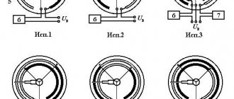
In any case, to form a certain pulse duration supplied to the base of the transistor and opening the latter, reference and setting voltage sources, as well as a comparator, are used. Let's consider a simplified circuit in which the battery GB supplies the consumer Rн in a pulsed manner through the transistor VT. I’ll say right away that in this circuit I specifically did not use such elements necessary for the operation of the circuit: a capacitor, an inductor and a diode. This is done to simplify the understanding of the operation of the PWM, and not the entire converter.
To put it simply, a comparator has three terminals: two inputs and one output. The comparator works as follows. If the voltage value at the “+” input pin (non-inverting input) is higher than at the “-” input (inverting input), then the output of the comparator will be a high level signal. Otherwise - low level.
In our case, it is the high level signal that opens the transistor VT. Let's consider how the required pulse time duration ti is formed. To do this, we will use the following graph.
With WID, a sawtooth signal of a given frequency is supplied to one input of the comparator. It is also called the support. The second input is supplied with a reference voltage, which is compared with the reference voltage. As a result of the comparison, a pulse of the appropriate duration is formed at the output of the comparator.
We recommend reading: Logic chips
If there is a reference signal at the non-inverting input of the comparator, then there will be a pause first, and then a pulse. If a master signal is applied to the non-inverting input, there will first be a pulse, then a pause.
Thus, by changing the value of the specified signal, you can change the duty cycle, and, accordingly, the average voltage at the load.
They strive to make the frequency of the reference signal maximum in order to reduce the parameters of the chokes and capacitors (not shown in the diagram). The latter leads to a reduction in the weight and dimensions of the switching power supply.
Electronics for everyone
Several times now I have cursed with the strange word PWM . It's time to clarify and explain what it is. In general, I have already described this mode of operation, but I will still repeat it as part of my course.
In short, Pulse Width Modulation (in bourgeois notation this mode is called PWM - Pulse Width Modulation ) is a way of specifying an analog signal using a digital method , that is, from a digital output that gives only zeros and ones to obtain some smoothly changing values. It sounds like nonsense, but nevertheless it works. And the point is:
Imagine a heavy flywheel that you can rotate with an engine. Moreover, you can either turn the engine on or off. If you turn it on constantly, the flywheel will spin up to its maximum value and continue to spin. If you turn it off, it will stop due to friction forces.
But if the engine is turned on for ten seconds every minute, the flywheel will spin up, but not at full speed - high inertia will smooth out the jerks from the engine turning on, and frictional resistance will not allow it to spin indefinitely.
The longer is turned on per minute, the faster the flywheel will spin. With PWM , we drive to the output a signal consisting of high and low levels (applicable to our analogy - we turn the engine on and off), that is, zeros and ones. And then all this is passed through an integrating chain (in analogy - a flywheel). As a result of integration, the output will have a voltage value equal to the area under the pulses.
With the duty cycle (the ratio of the period duration to the pulse duration), you can smoothly change this area, and therefore the output voltage. Thus, if the output is solid 1, then the output will have a high level voltage, in the case of my robot, the output from the L293 is 12 volts, if zeros, then zero. And if 50% of the time the level is high, and 50% low, then 6 volts. The integrating chain here will be the mass of the motor armature, which has a fairly large inertia.
What happens if you take and drive a PWM signal not from zero to maximum, but from minus to plus. Let's say from +12 to -12. And you can set a variable signal! When the input is zero, the output is -12V, when there is one, then +12V. If the duty cycle is 50%, then the output is 0V. If the duty cycle is changed according to a sinusoidal law from maximum to minimum, then we get... correctly! AC voltage. And if we take three such PWM generators and drive through them sinusoids shifted by 120 degrees from each other, we will get the most common three-phase voltage, which means hello brushless asynchronous and synchronous motors - the fetish of all aircraft modellers. All modern industrial AC drives are built on this principle. All sorts of Unidrive and Omron Jxx A regular RC chain can be used as a smoothing integrating circuit in PWM:
So, the principle is clear, let's proceed to implementation. The PWM signal can be made both on operational amplifiers and on a microcontroller. Moreover, the latter can do this simply masterfully, since they already have everything for this. Hardware PWM In the case of the ATMega16, the easiest way to do this is on its PWM generator, which is built into the timers. Moreover, in the first timer we have two channels. So, without much effort, ATmega16 can simultaneously implement four PWM . How it's implemented The timer has a special OCR comparison register**
. When the value in the timer counter register reaches the value in the comparison register, the following hardware events may occur:
- Interrupt by coincidence
- Changing the state of the external comparison output OC** .
The comparison outputs are routed outside to the microcontroller pins
On the Pinboard demo board, LEDs are connected to these pins. And if you place the jumpers along, towards the RC inscription, then an integrating chain will be connected to the PWM output.
For Pinboard II there is little difference in connection. The jumpers here are grouped into one block. And the LEDs and RC chains are grouped in the upper left corner of the board.
Let's assume that we have configured our PWM generator so that when the value in the counting register is greater than in the comparison register, then the output is 1, and when it is less, then 0. What will happen? The timer will count as it should, from zero to 256, with a frequency that we will configure with the timer prescaler bits. After overflow, it is reset to 0 and continues again.
As you can see, pulses appear at the output. And if we try to increase the value in the comparison register, the pulse width will become narrower.
So by changing the value in the comparison register, you can change the duty cycle of the PWM signal. And if we pass this PWM signal through a smoothing RC chain (integrator), we will get an analog signal. A timer can have any number of comparison registers. Depends on the MK model and the type of timer. For example, Atmega16
- Timer0 - one comparison register
- Timer1 - two comparison registers (16-bit!)
- Timer2 - one comparison register
Total - four channels. In new AVRs there are also three comparison registers per timer, which allows one MK to simply organize a breakthrough of independent PWM channels. There are several PWM modes themselves: Fast PWM
In this mode, the counter counts from zero to
255 , after reaching overflow it is reset to zero and counting starts again. When the value in the counter reaches the value of the comparison register, the corresponding OCxx will be reset to zero. When the counter is reset, this pin is set to 1. And that’s it! The frequency of the resulting PWM signal is determined simply: The processor frequency is 8 MHz, the timer ticks to 256 with a clock frequency. This means that one PWM period will be equal to 8000,000/256 = 31250Hz. Not bad at all. It won't be faster - this is the maximum speed on the internal 8 MHz clock generator.
But if you switch the FUSE bits to an external quartz, you can boost the MK to 16 MHz. It is still possible to increase the resolution by making the count 8, 9, 10 bits (if the bit depth of the timer allows), but we must take into account that increasing the bit depth, together with increasing the discreteness of the output analog signal, sharply reduces the PWM frequency. Phase Correct PWM
PWM with precise phase.
It works similarly, but here the counter counts slightly differently. First from 0 to 255, then from 255 to 0. The OCxx pin is reset on the first match, and set on the second. But the PWM drops by half due to the longer period. Its main purpose is to make multiphase PWM signals, for example, a three-phase sine wave. So that when the duty cycle changes, the phase shift angle between two PWM signals does not change. Those. the centers of the pulses in different channels and at different duty cycles will coincide.
Another subtlety:
To avoid pulse curves, any value enters the comparison register through a buffer register and is entered only when the value in the counter reaches its maximum.
Those. to the beginning of a new period of the PWM pulse. Clear Timer On Compare
Reset when comparing. This is most likely PFM - a pulse-frequency simulated signal. It works a little differently here than in other modes. Here the counting timer ticks not from 0 to the limit, but from 0 to the comparison register! And then it resets.
As a result, the output pulses are always the same duty cycle, but of different frequencies. And most often this mode is used when it is necessary to count periods with a timer (and generate an interrupt) with a specified accuracy. For example, we need an interrupt every millisecond. And to be sure. How can this be done more easily? Through STS Mode! Let our frequency be 8 MHz. The prescaler will be 64, so the timer tick frequency will be 125000 Hz. And we need an interrupt with a frequency of 1000Hz. Therefore, we set up an interrupt to coincide with the number 125. It reached 125 - gave an interrupt, reset to zero. It reached 125 - gave an interruption, reset to zero. And so on endlessly until we turn it off. Here is the exact ticker for you. No, of course, you can do it manually. Through overflow, i.e. ticked until it overflowed, reloaded the required value TCNTx = 255-125 in the interrupt handler, did the necessary useful things and ticked until it overflowed again. But it’s more beautiful through STS! 
Equipment
And now the control registers with which all this disgrace is set and programmed.
I will describe it using the example of Dual-Channel FastPWM on timer 1. In others everything is similar. Datashit in the teeth and forward. So, registers TCCR1A and TCCR1B . Gee, who would doubt it %) I'll write them down bit by bit. Register TCCR1A , bits COM1A1:COM1A0 and COM1B1:COM1B0 . This group determines the behavior of the comparison output of OC1A and OC1B , respectively.
| COMxx1 | COMxx0 | Output mode |
| 0 | 0 | the output is uncoupled from the comparison register and does not change in any way. |
| 0 | 1 | The behavior of the output depends on the mode specified in the WGM, it differs for different modes (FastPWM, FC PWM, Compar out) and different MKs, you need to check the datasheet. |
| 1 | 0 | direct PWM (reset when matched and set when count is reset) |
| 1 | 1 | reverse PWM (reset on zero and set on match) |
Register TCCR1A , bits WGM11 and WGM10 together with bits WGM12 and WGM13 located in register TCCR1B set the operating mode of the generator.
| WGM13 | WGM12 | WGM11 | WGM10 | Operating mode |
| 0 | 1 | 0 | 1 | Fast PWM 8 bit |
| 0 | 1 | 1 | 0 | Fast PWM 9 bit |
| 0 | 1 | 1 | 1 | Fast PWM 10 bit |
WGM bit combinations specify P hase Correct PWM and CTC ( OCxx on match) modes. If you are interested, then read the datasheet, I didn’t find much interesting there for myself, except for Phase Correct PWM . And now speed is more important to me, not phase accuracy. After that, all that remains is to start the timer by setting the CS10 (counting clock pulses with a 1:1 divider ) Code example:
Let's try to play with the brightness of the LEDs using PWM signals. Connect jumpers to power LED1 and LED2
For the Pinboard II version everything is similar, adjusted for a different arrangement of jumpers:
Now everything is ready, you can write code. First, in the device initialization section, I add a timer setting to start PWM and prepare pins.
| 1 2 3 4 5 6 7 8 9 10 11 12 | ;FastPWM Init SETB DDRD,4,R16 ; DDRD.4 = 1 Output ports SETB DDRD,5,R16 ; DDRD.5 = 1 ; We set the OS** output mode for both PWM channels to reset if there is a match. ; COM1A = 10 and COM1B = 10 ; We also set the FAST PWM 8bit mode (the timer is 16-bit and allows for a larger width of the PWM signal. Up to 10 bits. WGM = 0101 ; All that remains is to start the timer at the MK frequency CS = 001 OUTI TCCR1A,2<<<<<< |
;FastPWM Init SETB DDRD,4,R16 ; DDRD.4 = 1 Output ports SETB DDRD,5,R16 ; DDRD.5 = 1 ; We set the OS** output mode for both PWM channels to reset if there is a match. ; COM1A = 10 and COM1B = 10 ; We also set the FAST PWM 8bit mode (the timer is 16-bit and allows for a larger width of the PWM signal. Up to 10 bits. WGM = 0101 ; All that remains is to start the timer at the MK frequency CS = 001 OUTI TCCR1A,2<<<<<<
Ready! Now the PWM of timer 1 generates a signal at the outputs OC1A and OC1B. Let's put the number 255/3 = 85 and 255/2 = 128 into the comparison registers of the first and second channels. Since we have an 8-bit PWM, the transfer goes only to the low-order bit. The eldest remains zero. But the comparison registers here are 16-bit, so we need to load both bytes at once. Don't forget to disable interrupts (this is important!!! because atomic access)
| 1 2 3 4 5 6 7 | CLI OUTI OCR1AH,0 OUTI OCR1AL,85 OUTI OCR1BH,0 OUTI OCR1BL,128 SEI |
CLI OUTI OCR1AH,0 OUTI OCR1AL,85 OUTI OCR1BH,0 OUTI OCR1BL,128 SEI
Let's go! We flash it, poke at the legs of the microcontroller with an oscilloscope - we see the following picture by channel:
Just as we planned. From the first channel the pulse duration is 1/3 of the period, and from the second it is 1/2. Well, the LEDs light up with different brightness. One is brighter, the other is dimmer. By changing the value in the OCR*** registers we can change the duty cycle. Let's make the LED smoothly change its brightness from zero to maximum. As you remember, we had a program there with an LED blinking on a timer. Let's correct it a little, make sure that the LED does not blink according to the timer, but the value in the comparison registers OCR1A and OCR1B changes. Moreover, it will change in different directions
| 1 2 3 4 5 6 7 8 9 10 11 12 13 14 15 16 17 18 19 20 21 22 23 24 25 26 27 28 29 30 31 32 33 34 35 36 37 38 39 40 41 42 43 44 45 46 47 48 49 50 51 52 53 54 55 | ; Main ================================================================= ======== Main: LDS R16,TCNT ; Load numbers into registers LDS R17,TCNT+1 CPI R16.0x10 ; Let's compare the byte-by-byte excerpt BRCS NoMatch CPI R17.0x01 ; The shutter speed was made shorter = 0x0110 BRCS NoMatch; If it matches, then we do the action Match: CLI ; Disabling interrupts, because atomic access; Changing the first channel; The peculiarity of 16-bit registers is that they must be read and written correctly. ; The low byte is read first, then the high byte. This is necessary so that the younger one does not have time to change; (after all, it can tick on a timer) while the eldest is read first. Lay them in reverse; ok. First the eldest, then the youngest. True, for OCR registers this is not a big deal; the differences are static, but for TCNT they are very different! IN R16,OCR1AL ; We got the first comparison byte IN R17,OCR1AH; it is 16-bit, but the high byte will be 0 INC R16; Increased OUT OCR1AH,R17 ; And they put them back OUT OCR1AL,R16 ; Change the second channel IN R16,OCR1BL ; We got the second comparison byte IN R17,OCR1BH ; it is 16-bit, but the high byte will be 0 DEC R16; Decreased OUT OCR1BH,R17 ; And they put them back OUT OCR1BL,R16 SEI ; End of atomic access; Now we need to reset the counter to zero, otherwise during the same iteration of the main loop; We will get here more than once - the timer will not have time to reach 255 values; so that the number in the first two bytes of the counter changes. CLR R16; We need zero CLI; The timer also changes in the interrupt. Need ; atomic access. Disable interrupts OUT TCNT0,R16 ; Zero to the timer counter register STS TCNT, R16 ; Zero in the first byte of the counter in RAM STS TCNT+1,R16 ; Zero in the second byte of the counter in RAM STS TCNT+2,R16 ; Zero in the third byte of the counter in RAM STS TCNT+3,R16 ; Zero in the first byte of the counter in RAM SEI; Enable interrupts. ; If it doesn’t match, we don’t do NoMatch: NOP INCM CCNT ; The barrel organ continues to rotate, idling JMP Main |
; Main ================================================================= ======== Main: LDS R16,TCNT ; Load numbers into registers LDS R17,TCNT+1 CPI R16.0x10 ; Let's compare the byte-by-byte excerpt BRCS NoMatch CPI R17.0x01 ; The shutter speed was made shorter = 0x0110 BRCS NoMatch; If it matches, then we do the action Match: CLI ; Disabling interrupts, because atomic access; Changing the first channel; The peculiarity of 16-bit registers is that they must be read and written correctly. ; The low byte is read first, then the high byte. This is necessary so that the younger one does not have time to change; (after all, it can tick on a timer) while the eldest is read first. Lay them in reverse; ok. First the eldest, then the youngest. True, for OCR registers this is not a big deal; the differences are static, but for TCNT they are very different! IN R16,OCR1AL ; We got the first comparison byte IN R17,OCR1AH; it is 16-bit, but the high byte will be 0 INC R16; Increased OUT OCR1AH,R17 ; And they put them back OUT OCR1AL,R16 ; Change the second channel IN R16,OCR1BL ; We got the second comparison byte IN R17,OCR1BH ; it is 16-bit, but the high byte will be 0 DEC R16; Decreased OUT OCR1BH,R17 ; And they put them back OUT OCR1BL,R16 SEI ; End of atomic access; Now we need to reset the counter to zero, otherwise during the same iteration of the main loop; We will get here more than once - the timer will not have time to reach 255 values; so that the number in the first two bytes of the counter changes. CLR R16; We need zero CLI; The timer also changes in the interrupt. Need ; atomic access. Disable interrupts OUT TCNT0,R16 ; Zero to the timer counter register STS TCNT, R16 ; Zero in the first byte of the counter in RAM STS TCNT+1,R16 ; Zero in the second byte of the counter in RAM STS TCNT+2,R16 ; Zero in the third byte of the counter in RAM STS TCNT+3,R16 ; Zero in the first byte of the counter in RAM SEI; Enable interrupts. ; If it doesn’t match, we don’t do NoMatch: NOP INCM CCNT ;
The barrel organ continues to rotate, idling JMP Main Now let's turn on the mode with precise phase (WGM = 0001) and see how the duty cycle changes.
| 1 2 | OUTI TCCR1A,2<<<<<< |
OUTI TCCR1A,2<<<<<<<
PWM on interrupts. But there’s an ambush - the board is already wired, I wanted PWM , and the OCxx are already used for other purposes. It's okay, with a little blood you can fix it. We also run PWM , only:
- Disconnect pins OCxx from the comparison register.
- We add two interrupt handlers for comparison and for overflow. In the comparison interrupt we reset the required bit, in the counter overflow interrupt we set it.
It's simple Example:
| 1 2 3 4 5 6 7 8 9 10 11 12 13 14 15 16 17 18 19 20 21 | ;FastPWM Init on interrupts; PWM will be on pins 3 and 6 of port D SETB DDRD,3,R16; DDRD.3 = 1 Output ports SETB DDRD,6,R16 ; DDRD.6 = 1 ; We set the OS** output mode to off for both PWM channels. ; COM1A = 00 and COM1B = 00 ; We also set the FAST PWM 8bit mode (the timer is 16-bit and allows ; a large width of the PWM signal. Up to 10 bits. WGM = 0101 ; All that remains is to start the timer at the MK frequency CS = 001 OUTI TCCR1A,0<<<<<< |
;FastPWM Init on interrupts;
PWM will be on pins 3 and 6 of port D SETB DDRD,3,R16; DDRD.3 = 1 Output ports SETB DDRD,6,R16 ; DDRD.6 = 1 ; We set the OS** output mode to off for both PWM channels. ; COM1A = 00 and COM1B = 00 ; We also set the FAST PWM 8bit mode (the timer is 16-bit and allows for a larger width of the PWM signal. Up to 10 bits. WGM = 0101 ; All that remains is to start the timer at the MK frequency CS = 001 OUTI TCCR1A,0<<<<<<< All that remains is register handlers and vectors:
| 1 2 3 4 5 6 7 8 9 10 11 12 13 14 15 16 17 18 19 20 21 22 23 24 25 26 27 28 29 30 31 32 33 34 35 36 37 38 39 40 41 42 43 44 45 46 47 48 49 50 51 52 53 54 55 56 57 58 59 60 61 62 63 64 65 66 67 68 69 70 71 72 | .CSEG .ORG $000 ; (RESET) RJMP Reset .ORG $002 RETI ; (INT0) External Interrupt Request 0 .ORG $004 RETI ; (INT1) External Interrupt Request 1 .ORG $006 RETI ; (TIMER2 COMP) Timer/Counter2 Compare Match .ORG $008 RETI ; (TIMER2 OVF) Timer/Counter2 Overflow .ORG $00A RETI ; (TIMER1 CAPT) Timer/Counter1 Capture Event .ORG $00C RJMP Timer1_OCA ; (TIMER1 COMPA) Timer/Counter1 Compare Match A .ORG $00E RJMP Timer1_OCB ; (TIMER1 COMPB) Timer/Counter1 Compare Match B .ORG $010 RJMP Timer1_OVF ; (TIMER1 OVF) Timer/Counter1 Overflow .ORG $012 RJMP Timer0_OV ; (TIMER0 OVF) Timer/Counter0 Overflow .ORG $014 RETI ; (SPI,STC) Serial Transfer Complete .ORG $016 RETI ; (USART,RXC) USART, Rx Complete .ORG $018 RETI ; (USART,UDRE) USART Data Register Empty .ORG $01A RETI ; (USART,TXC) USART, Tx Complete .ORG $01C RETI ; (ADC) ADC Conversion Complete .ORG $01E RETI ; (EE_RDY) EEPROM Ready .ORG $020 RETI ; (ANA_COMP) Analog Comparator .ORG $022 RETI ; (TWI) 2-wire Serial Interface .ORG $024 RETI ; (INT2) External Interrupt Request 2 .ORG $026 RETI ; (TIMER0 COMP) Timer/Counter0 Compare Match .ORG $028 RETI ; (SPM_RDY) Store Program Memory Ready .ORG INT_VECTORS_SIZE ; End of interrupt table; Interrupts =========================================================== Timer0_OV: PUSHF PUSH R17 PUSH R18 PUSH R19 INCM TCNT POP R19 POP R18 POP R17 POPF RETI ; Here are our PWM handlers Timer1_OCA: SBI PORTD,3 RETI Timer1_OCB: SBI PORTD,6 RETI Timer1_OVF: CBI PORTD,3 CBI PORTD,6 RETI ; End Interrupts =========================================== |
.CSEG .ORG $000 ;
(RESET) RJMP Reset .ORG $002 RETI ; (INT0) External Interrupt Request 0 .ORG $004 RETI ; (INT1) External Interrupt Request 1 .ORG $006 RETI ; (TIMER2 COMP) Timer/Counter2 Compare Match .ORG $008 RETI ; (TIMER2 OVF) Timer/Counter2 Overflow .ORG $00A RETI ; (TIMER1 CAPT) Timer/Counter1 Capture Event .ORG $00C RJMP Timer1_OCA ; (TIMER1 COMPA) Timer/Counter1 Compare Match A .ORG $00E RJMP Timer1_OCB ; (TIMER1 COMPB) Timer/Counter1 Compare Match B .ORG $010 RJMP Timer1_OVF ; (TIMER1 OVF) Timer/Counter1 Overflow .ORG $012 RJMP Timer0_OV ; (TIMER0 OVF) Timer/Counter0 Overflow .ORG $014 RETI ; (SPI,STC) Serial Transfer Complete .ORG $016 RETI ; (USART,RXC) USART, Rx Complete .ORG $018 RETI ; (USART,UDRE) USART Data Register Empty .ORG $01A RETI ; (USART,TXC) USART, Tx Complete .ORG $01C RETI ; (ADC) ADC Conversion Complete .ORG $01E RETI ; (EE_RDY) EEPROM Ready .ORG $020 RETI ; (ANA_COMP) Analog Comparator .ORG $022 RETI ; (TWI) 2-wire Serial Interface .ORG $024 RETI ; (INT2) External Interrupt Request 2 .ORG $026 RETI ; (TIMER0 COMP) Timer/Counter0 Compare Match .ORG $028 RETI ; (SPM_RDY) Store Program Memory Ready .ORG INT_VECTORS_SIZE ; End of interrupt table; Interrupts =========================================================== Timer0_OV: PUSHF PUSH R17 PUSH R18 PUSH R19 INCM TCNT POP R19 POP R18 POP R17 POPF RETI ; Here are our PWM handlers Timer1_OCA: SBI PORTD,3 RETI Timer1_OCB: SBI PORTD,6 RETI Timer1_OVF: CBI PORTD,3 CBI PORTD,6 RETI ; End Interrupts ======================================================== Why am I not in these handlers? save registers and SREG? There's no need! SBI commands change only specific bits (and we don’t need anything else), without affecting flags and other registers. They launched it... And they got complete bullshit. Those. There seems to be PWM, but for some reason it flickers like hell. And the oscilloscope at this moment is complete trash. Who is guilty? Apparently there is an interrupt conflict. All that remains is to find out where exactly. Now I will give you a practical example of real-time debugging. So, what we have: PWM, as such, works. The duty cycle changes. This means our algorithm is correct. But the durations vary. Why? Apparently because something prevents them from getting up on time. When do we have fronts? That's right - by interruptions. And timer interrupts. Those. shouldn't lie. However, this is how it works. Let's find out where we have a conflict. The first step is to add debugging information to the handler code. We will invert the bit in the interrupt handler. Let it be PD7 - go to the handler, invert it. We came in and turned around. As a result, we will have a rectangular signal at the output of this bit, where each edge is an interrupt trigger. It will serve us as a ruler measuring time.
| 1 2 3 4 5 6 7 8 9 10 11 12 13 14 15 16 17 18 19 20 21 22 23 24 25 26 27 28 29 30 31 32 33 | ; Interrupts =========================================================== Timer0_OV: PUSHF PUSH R17 PUSH R18 PUSH R19 INCM TCNT POP R19 POP R18 POP R17 POPF RETI ; Setting the PWM bit of channel A Timer1_OCA: SBI PORTD,3 RETI ; Setting the PWM bit of channel B Timer1_OCB: SBI PORTD,6 RETI ;Resetting the PWM bit of channel A and B Timer1_OVF: CBI PORTD,3 CBI PORTD,6 ;DEBUG PIN BEGIN ————— PUSHF INVBM PORTD,7 POPF ;DEBUG PIN END — ————— RETI |
;
Interrupts =========================================================== Timer0_OV: PUSHF PUSH R17 PUSH R18 PUSH R19 INCM TCNT POP R19 POP R18 POP R17 POPF RETI ; Setting the PWM bit of channel A Timer1_OCA: SBI PORTD,3 RETI ; Setting the PWM bit of channel B Timer1_OCB: SBI PORTD,6 RETI ;Resetting the PWM bit of channel A and B Timer1_OVF: CBI PORTD,3 CBI PORTD,6 ;DEBUG PIN BEGIN ————— PUSHF INVBM PORTD,7 POPF ;DEBUG PIN END — ————— RETI Bit inversion is impossible without logical operations, so flags must be saved. From the picture it became clear that we have an interruption in comparison. Let's try to see with which interruptions the conflict occurs. We don’t have any special options - we have four interruptions here. And the most obvious conflict is Timer0_OV vs Timer1_OCA vs Timer1_OCB. OCA and OCB conflict only when their counting registers are compared - the call occurs almost simultaneously, but the handlers themselves are short - only a few clock cycles, so the bounce is not so strong. But Timer0_OV does a fairly powerful stack load and also subtracts a four-byte variable. Those. The Timer1_OC* bit setting handler can delay the Timer1_OC* bit setting handler by 20 cycles, which is why such brutal rattles occur. Let's test this idea. Let's enable interrupts in the Timer0_0V handler
| 1 2 3 4 5 6 7 8 9 10 11 12 13 14 15 16 17 18 19 20 21 22 23 24 25 26 27 28 | ; Interrupts ========================================================== Timer0_OV: SEI PUSHF PUSH R17 PUSH R18 PUSH R19 INCM TCNT POP R19 POP R18 POP R17 POPF RETI ; Setting the PWM bit of channel A Timer1_OCA: SBI PORTD,3 RETI ; Setting the PWM bit of channel B Timer1_OCB: SBI PORTD,6 RETI ;Resetting the PWM bit of channel A and B Timer1_OVF: CBI PORTD,3 CBI PORTD,6 RETI |
;
Interrupts ========================================================== Timer0_OV: SEI PUSHF PUSH R17 PUSH R18 PUSH R19 INCM TCNT POP R19 POP R18 POP R17 POPF RETI ; Setting the PWM bit of channel A Timer1_OCA: SBI PORTD,3 RETI ; Setting the PWM bit of channel B Timer1_OCB: SBI PORTD,6 RETI ;Resetting the PWM bit of channel A and B Timer1_OVF: CBI PORTD,3 CBI PORTD,6 RETI The picture immediately improved. Now the more important (for us important) interrupt is moving the handler away from Timer 0. But here we need to look out for possible risks:
- Deeper stack loading
- Atomic access to the four-byte TCNT variable is broken, so if we had some other interrupt that changed TCNT, it would have to be disabled locally. Otherwise, we would have ended up with such trash that it would be easier to rewrite the program again than to debug it
. PWM on timers When everything is really bad, you can do it on any timer. We add a finite state machine into the timer overflow interrupt handler, which will first load the duration of the low level into the timer, and the next time it enters, the duration of the high level. Well, of course, the processor’s legs will work as they should. Thus, you can hang a lot of PWM channels on one timer, but you will get bored with the code implementation of all this. And it will eat up CPU time quite a bit. Not to mention the rattles that were just mentioned. This is for aesthetes and perverts :))))) Source for the article
PWM – pulse width modulation
PWM is predominantly used to generate a sinusoidal signal. PWM is often used to control the operation of an inverter converter. The inverter is designed to convert DC energy into AC energy.
Let's consider the simplest voltage inverter circuit.
At one point in time, a pair of transistors VT1 and VT3 opens. A path is created for the flow of current from the battery GB through the active-inductive load RнLн. At the next moment, VT1 and VT3 are locked, and diagonally opposite transistors VT2 and VT4 are open. Now current flows from the battery through RnLn in the opposite direction. Thus, the current across the load changes its direction and is therefore variable. As you can see, the load current is not sinusoidal. Therefore, PWM is used to obtain a sinusoidal current waveform.
There are several types of PWM: unipolar, bipolar, one-way, two-way. Here we will not dwell on each specific type, but will consider the general approach.
A sinusoid is used as a modulating signal, and a triangular signal is used as a reference signal. As a result of comparing these signals, the durations of pulses and pauses are formed (lower graph), which control the operation of transistors VT1...VT4. Please note that the voltage amplitude across the load is always equal to the amplitude of the power supply. The pulse repetition period also remains unchanged. Only the width of the opening pulse changes. Therefore, when a load is connected, the current flowing through it will have a sinusoidal shape (shown by the dotted line in the lower graph).
So, the main difference between WIDTH and PWM is that with pulse-width control, the pulse and pause times remain constant. And with pulse-width modulation, the durations of pulses and pauses change, which makes it possible to realize an output signal of a given shape.
PWM voltage regulator 12 volts - description
A feature of these circuits is the ability to use virtually any available operational amplifiers with a supply voltage of 12 volts, for example, the LM324 operational amplifier or the LM358 operational amplifier.
By changing the voltage at the non-inverting input of the operational amplifier (pin 3), you can change the output voltage. Thus, these circuits can be used as a current and voltage regulator, in dimmers and also as a DC motor speed regulator.
The circuits are quite simple, they consist of simple and accessible radio components and, if installed correctly, they immediately begin to work. A powerful field-effect n-channel transistor is used as a control switch. The power of the field-effect transistor, as well as the area of the radiator, must be selected according to the current consumption of the load.
To prevent breakdown of the gate of the field-effect transistor, when using a PWM regulator with a supply voltage of 24 volts, it is necessary to connect a resistance of 1 kOhm between the gate of VT2 and the collector of transistor VT1, and connect a 15-volt zener diode in parallel with resistance R7.
If it is necessary to change the voltage on a load, one of the contacts of which is connected to ground (this occurs in a car), then a circuit is used in which the drain of an n-channel field-effect transistor is connected to the plus of the power source, and the load is connected to its source.
It is desirable to create conditions under which the field-effect transistor will open fully, the gate control circuit should contain a node with an increased voltage of the order of 27...30 volts. In this case, the voltage between source and gate will be more than 15 V.
If the load current consumption is less than 10 amperes, then it is possible to use powerful field-effect p-channel transistors in the PWM regulator.
In the second PWM circuit, the 12 volt voltage regulator changes and the type of transistor VT1 changes, and the direction of rotation of the variable resistor R1 also changes. So, in the first version of the circuit, a decrease in the control voltage (the potentiometer handle moves to the “-” power source) causes an increase in the output voltage. The second option has the opposite.
How to test a PWM controller
There are several ways to test a PWM controller. You can, of course, do this without a multimeter, but why bother if you can use a normal device.
Before checking the operation of the PWM controller, it is necessary to perform basic diagnostics of the power supply itself. It works like this:
Step 1. Carefully inspect the power supply itself, in which the PWM is installed, when turned off. In particular, electrolytic capacitors should be carefully inspected for swelling.
Step 2. Check the fuse and input filter elements of the power supply for serviceability.
Step 3. Check for short circuit or open circuit of the rectifier bridge diodes. You can ring them without desoldering them from the board. In this case, you must be sure that the circuit being tested is not shunted by the transformer windings or resistor. If you suspect this, you will still have to unsolder the elements and check them separately.
Step 4. Check the serviceability of the output circuits, namely electrolytic capacitors of low-frequency filters, rectifier diodes, diode assemblies, etc.
Step 5. Check the power transistors of the high-frequency converter and the transistors of the control cascade. In this case, be sure to check the return diodes that are connected in parallel to the collector-emitter electrodes of the power transistors.
Checking the PWM controller - video instructions:
Reasons and applications of PWM
The principle of pulse width modulation is used in speed controllers of powerful asynchronous motors. In this case, a modulating signal of adjustable frequency (single-phase or three-phase) is generated by a low-power sine wave generator and superimposed on the carrier in an analogue way. The output produces a PWM signal, which is supplied to the switches of the required power. Then you can pass the resulting sequence of pulses through a low-pass filter, for example through a simple RC chain, and isolate the original sinusoid. Or you can do without it - filtration will occur naturally due to the inertia of the engine. Obviously, the higher the carrier frequency, the closer the output waveform is to the original sine wave.
We recommend reading: Running Lights
A natural question arises: why can’t the generator signal be amplified immediately, for example, by using powerful transistors? Because the regulating element operating in linear mode will redistribute power between the load and the switch. In this case, significant power is wasted on the key element. If a powerful control element operates in switching mode (thyristor, triac, RGBT transistor), then the power is distributed over time. Losses will be much lower, and efficiency will be much higher.
In digital technology there is no special alternative to pulse width control. The amplitude of the signal there is constant; the voltage and current can only be changed by modulating the carrier along the pulse width and subsequently averaging it. Therefore, PWM is used to regulate voltage and current on those objects that can average a pulse signal. Averaging occurs in different ways:
- Due to load inertia. Thus, the thermal inertia of thermoelectric heaters and incandescent lamps allows the controlled objects not to noticeably cool down in pauses between pulses.
- Due to the inertia of perception. The LED manages to go out from pulse to pulse, but the human eye does not notice this and perceives it as a constant glow with varying intensities. This principle is used to control the brightness of LED monitors. But imperceptible blinking with a frequency of several hundred hertz is still present and causes eye fatigue.
- Due to mechanical inertia. This property is used when controlling brushed DC motors. If the control frequency is correctly selected, the motor does not have time to slow down during dead pauses.
Therefore, PWM is used where the average value of voltage or current plays a decisive role. In addition to the common cases mentioned, the PWM method is used to regulate the average current in welding machines and battery chargers, etc.
If natural averaging is not possible, in many cases this role can be taken over by the already mentioned low-pass filter (LPF) in the form of an RC chain. For practical purposes, this is enough, but you need to understand that it is impossible to isolate the original signal from PWM using a low-pass filter without distortion. After all, the PWM spectrum contains an infinitely large number of harmonics, which will inevitably fall into the filter passband. Therefore, you should not create illusions about the shape of the reconstructed sinusoid.
PWM control of an RGB LED is very effective and efficient. This device has three pn junctions - red, blue, green. By changing the brightness of each channel separately, you can get almost any LED color (with the exception of pure white). The possibilities for creating lighting effects using PWM are endless.
The most common application of a pulse-width modulated digital signal is to regulate the average current or voltage flowing through a load. But non-standard use of this type of modulation is also possible. It all depends on the imagination of the developer.
Overview of typical circuits
You can regulate the rotation of the shaft of a low-power electric motor by connecting a power resistor in series with no. However, this option has very low efficiency and the inability to smoothly change speed. To avoid such a nuisance, you should consider several regulator circuits that are used most often.
As you know, PWM has a constant pulse amplitude. In addition, the amplitude is identical to the supply voltage. Consequently, the electric motor will not stop even when running at low speeds.
The second option is similar to the first. The only difference is that an operational amplifier is used as the master oscillator. This component has a frequency of 500 Hz and produces triangular-shaped pulses. Adjustment is also carried out using a variable resistor.
How to make it yourself?
There are various options for adjustment schemes. Let us present one of them in more detail.
Here is how it works:
Initially, this device was developed to adjust the commutator motor in electric vehicles. We were talking about one where the supply voltage is 24 V, but this design is also applicable to other engines.
The weak point of the circuit, which was identified during testing of its operation, is its poor suitability at very high current values. This is due to some slowdown in the operation of the transistor elements of the circuit.
It is recommended that the current be no more than 70 A. There is no current or temperature protection in this circuit, so it is recommended to build in an ammeter and monitor the current visually. The switching frequency will be 5 kHz, it is determined by capacitor C2 with a capacity of 20 nf.
As the current changes, this frequency can change between 3 kHz and 5 kHz. Variable resistor R2 is used to regulate the current. When using an electric motor at home, it is recommended to use a standard type regulator.
At the same time, it is recommended to select the value of R1 in such a way as to correctly configure the operation of the regulator. From the output of the microcircuit, the control pulse goes to a push-pull amplifier using transistors KT815 and KT816, and then goes to the transistors.
The printed circuit board has a size of 50 by 50 mm and is made of single-sided fiberglass:
This diagram additionally shows 2 45 ohm resistors. This is done for the possible connection of a regular computer fan to cool the device. When using an electric motor as a load, it is necessary to block the circuit with a blocking (damper) diode, which in its characteristics corresponds to twice the load current and twice the supply voltage.
Recommended reading: Levitating globe
Operating the device in the absence of such a diode may lead to failure due to possible overheating. In this case, the diode will need to be placed on the heat sink. To do this, you can use a metal plate that has an area of 30 cm2.
Regulating switches work in such a way that the power losses on them are quite small. In the original design, a standard computer fan was used. To connect it, a limiting resistance of 100 Ohms and a supply voltage of 24 V were used.
The assembled device looks like this:
When manufacturing a power unit (in the lower figure), the wires must be connected in such a way that there is a minimum of bending of those conductors through which large currents pass. We see that the manufacture of such a device requires certain professional knowledge and skills. Perhaps in some cases it makes sense to use a purchased device.
How to connect to the load
The PWM signal generator should not be connected directly to the load, because it is low-current and will most likely burn everything out immediately. In order to control the load, you need a switch on a mosfet transistor. We take an N-channel mosfet transistor IRF3205 and assemble everything according to the diagram:
Arduino PWM on IRF3205
Resistor R1 is needed to protect the Arduino pin from burnout, and resistor R2 is needed to ensure that the transistor is completely closed when the Arduino does not provide an output signal.
As you can see, nothing complicated. Four elements and the PWM controller is ready. He can already control a single-color LED strip or some kind of motor.
If you need a three-color ribbon or more ribbons (we make multi-channel PWM), simply add keys to pins D3, D5, D6, D9, D10, D11 ( only PWM works on them ). In total, Arduino is capable of controlling the power of 6 devices simultaneously.
The IRF3205 is capable of withstanding currents of up to 70 Amps at voltages of up to 55 Volts; such characteristics are quite sufficient to solve most household problems.