Selecting a hitch
Any trailed or mounted device for motor vehicles, be it a trailer cart, a mower, a hiller, a harrow or any other equipment, is fixed using a hitch. If the base element is not suitable, the owner has a choice - buy a suitable one or make a hitch for the unit with his own hands.
Be that as it may, when deciding which of the mechanism options can best meet the functions performed by the unit, it is necessary to take into account a number of factors, the list of which includes:
- distinctive features of a cultivator or walk-behind tractor;
- scope of use of the unit - the duties it performs;
- equipment that will be integrated with it;
- loads;
- need for versatility.
Based on this, it is necessary to carefully familiarize yourself with the most frequently used devices and choose, taking as a basis the properties of what is best suited in this case.
Trailers for cars
Parameters, dimensions and general technical requirements
OST 37.001. 220-80
This standard applies to all types of trailers intended for towing by cars and minibuses on the roads of the general USSR network. The standard does not apply to trailers, technical specifications for which the design was approved before the introduction of this standard. The main terms used in the standard and their definitions are given in the reference appendix.
Parameters and sizes
1.1. The total design weight of the trailer must not exceed that permitted by the manufacturer of the towing vehicle, must not exceed the curb weight of the towing vehicle, and must not exceed 1800 kg.
1.2. The total structural weight of an unbraked trailer must not exceed that permitted by the manufacturer of the towing vehicle and must not be more than half the curb weight of the towing vehicle.
1.3. The vertical static load in the center of the ball joint of the coupling device for any weight state of the trailer must correspond to the value permitted by the manufacturer of the towing vehicle, but must not be less than 240 N (25 kgf) and more than 980 N (100 kgf).
1.4. The length of the trailer should not be more than 1.5 times the length of the main towing vehicle or more than 8 m.
1.5. The width of the trailer must not exceed the width of the main towing vehicle by more than 200 mm on each side and must not be more than 2.3 m.
1.6. The height of the trailer should not be more than 1.8 times the trailer track width or more than 3 m.
1.7. The center of gravity of a loaded trailer must be located in such a way that the ratio of the height of the center of gravity to the track of the trailer wheels is no more than 0.725.
1.8. The ground clearance of the trailer should not be less than the ground clearance of the main towing vehicle.
Technical requirements
2.1. General requirements
2.1.1. Trailers must be single-axle, but a tandem axle may be used.
2.1 2 A trailer with a horizontal inner floor, installed on a horizontal surface, must have a load of no more than 55% of its total weight on the tire(s) of one side.
2 1.3. The design of the trailer must be designed for movement as part of a road train of the full structural mass at the maximum speed permitted by the manufacturers of the traction vehicles.
2.1.4. The design and dimensions of the trailer drawbar (frame) must ensure the possibility of its deflection relative to the coupling ball installed on the vehicle at the angles specified by OST 37.001.096-77.
2.1.5. Trailers must be equipped with two non-removable safety chains (cables), which in the event of an emergency breakage (breakage) of the towbar should not allow the drawbar to touch the road surface, while ensuring control of the trailer.
2.1.6. Trailers must have two wheel chocks (“shoes”).
2.1.7. Trailers must have space for a jack.
2.1.8. The control for the parking brake system of trailers must be removable and located on the right side in the front of the drawbar (frame).
2.1.9. Trailers must be equipped with wheel protective devices (fenders, mudguards) if body parts do not perform the functions of this device.
2.1.10. The materials used for the manufacture of trailers must have resistance to fire from exposure to water, fuel and oils no lower than the resistance of materials of parts and assemblies for similar purposes of the main traction vehicle.
2.1.11. Painting of trailers and control of the appearance of the coating in accordance with GOST 7593-80.
2.1.12. The trailer must have a climatic design in accordance with GOST 15150-69, corresponding to the climatic design of the main traction vehicle, and must be designed for storage conditions in open areas.
2.1.13. The service life of the trailer in accordance with its purpose and operating conditions is regulated by regulatory and technical documentation approved in the prescribed manner.
2.2. Requirements for systems, components and assemblies
2.2.1. Trailer brake systems must comply with the requirements of OST 37.001.016 70.
2.2.2. The locking device for coupling with a traction vehicle must comply with the requirements of OST 37.001.096-77.
2.2.3. Electrical equipment, external lighting and signaling devices must comply with the requirements of GOST 3940-71. GOST 8769-75, GOST 10984-74 and GOST 20961-75.
2.2.4. Trailers must have brackets (or space) for attaching a license plate in accordance with GOST 3207-77.
2.2.5. To connect to the vehicle's electrical system, the trailer must have a plug in accordance with GOST 9209-76 with a connecting cable.
2.2.6. Trailers must have support legs that ensure the stability of the trailer when uncoupled and do not impair the cross-country ability of the road train.
When the vertical static load from the trailer locking device is more than 390 N (40 kgf), the front support leg must be equipped with a lifting-lowering mechanism that ensures installation of the locking device in the position required for coupling (uncoupling). When the mechanism is manually driven, the force on the handle should not exceed 118N (12 kgf).
Completeness
3.1. Trailers equipped with tires that are not unified with the main traction vehicle must have a spare wheel and a device for securing it.
3.2. Trailers must be supplied with the necessary tools and accessories if the set of tools and accessories of the main towing vehicle is insufficient to service the trailer.
Marking
4.1. Trailers must have a nameplate and markings in accordance with industry regulations and technical documentation.
4.2. Trailers must have an additional sign near the locking device in accordance with GOST 12971-67 indicating the total structural weight of the trailer; the maximum static load on the coupling ball.
Terms and definitions adopted in this standard TermDefinition Main traction vehicleAccording to GOST 3163-76 Twin axleTwo parallel axles of the trailer, the distance between which does not exceed 1 m.
If your trailer meets these requirements, passes an examination, and has checks, certificates, and a copy of the welder’s certificate, you will not have any problems registering with the traffic police.
How to make a trailer for a car video
DIY car trailer video
Do-it-yourself trailer is easy
Varieties
When selecting a hitch for a unit, you should take as a basis the most relevant type of element.
There are several varieties.
- Single and double – used when there are different models of attachments. It all depends on which ones are practiced and in what numbers.
- Reinforced – ideal for heavy motorcycles. Its distinctive feature is that it is more impressive - it is longer and thicker, which allows the auxiliary equipment to sink deeper into the soil.
- Customizable – with the option to change the angle of the shaft, through which you can adjust the level of fixation of attachments and thereby increase work productivity.
- Universal coupling device - involves aggregation with many modifications.
If a coupling device for a motorcycle of the required modification is not commercially available or there are individual requirements for it, creating it on your own will not be difficult, since we are talking about a rather simple mechanism.
Craftsmen, who make most of the “accessories” for motorcycles with their own hands, construct the “pipe-in-pipe” trailer coupling device from a crosspiece, from a cardan and other improvised elements preserved from various devices. The owners of such devices claim that it is possible to create such a unit without any problems by sharing personal experience and drawings of the coupling device on the Internet.
Disc hiller for walk-behind tractor
The most convenient option to use is a disk hiller.
To work with it, you need to exert a minimum of physical effort, and as the speed of movement decreases, its power increases, which has a positive effect on work efficiency.
In addition, the disc design of the hiller is versatile - with the help of such a tool you can carry out agricultural work both immediately after planting garden crops and during the period of their intensive growth.
The design of the disc hiller includes:
- disks;
- T-shaped leash (frame);
- racks;
- screw tappers.
Talpers are designed to adjust the angle of rotation of disks. The depth of immersion of the latter, as well as the force required to perform the work, depends on the latter. To facilitate the operator's work, the hiller is equipped with sliding bearings, which ensure reliability of the design and ease of operation.
The discs are made of alloy steel with a thickness of 1.5-2 mm. Their outer edges are curved, and in the center there is a hole for adapters with which they will be attached to the hiller frame. If it is not possible to make discs yourself, you can borrow them from an old seeder or other similar equipment.
This type of attachment greatly facilitates the process of harvesting potatoes, as well as other tuber crops.
The main structural elements of the potato digger are:
- welded frame;
- ploughshare;
- editorial node;
- cleaning drum.
The ploughshare, the moving part of the potato digger, is made of steel rods and one or more sharpened steel plates. The sharp edges and ends of the plowshare structural elements are blunted so as to prevent damage to the potato tubers.
To make a welded frame, you need a metal corner measuring about 60x40 mm, a profiled pipe and a section of channel No. 8. The dimensions, as well as the weight of the frame, which depends on the weight of the materials used and the features of the design solution adopted, must correspond to the dimensions and power of the walk-behind tractor.
The editorial unit is the main element of the potato digger.
To manufacture it, you will need two metal cylinders, which will act as cups for the connecting bushings - this design ensures the interaction of the drive and driven shafts.
Next, you need to make hubs from a metal pipe with a diameter of 25 mm, to which the transmission sprockets are welded. The latter are mounted on the bushings using prismatic keys.
The most difficult part of the potato digger is the cleaning drum. Its design includes a pair of roller chains of 94 links each, which are mounted on special rods.
This element, called the “squirrel wheel,” is fixed on two fixed axes, which ensures its mobility during rotation.
Thus, by the force of the engine shaft, the potato digger share, attached to the movable casing, will change the angle of inclination, making digging movements as the walk-behind tractor moves.
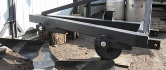
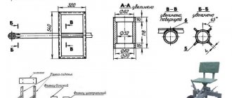
Hitch drawings for walk-behind tractor
Below are drawings of a universal hitch suitable for most popular brands of walk-behind tractors, such as: Tselina, OKA, Neva, Salyut, Favorit, etc.
The purpose of the universal hitch is in connection with a walk-behind tractor for attachments: harrows, plows, diggers, planters, etc.
Practical recommendations
If the power of the equipment does not exceed 5 hp. s., the optimal dimensions of the trailer in length and width will be 1.5 and 1 m. When the parameters of the body are calculated, pieces of the corrugated pipe are cut to the required length and a frame is welded from them. The design is quite rigid, so there is no need to install reinforcing elements in the corners. In order for the seam to be smooth and of high quality along its entire length, you should work on a flat surface, preferably using electric arc welding.
Body assembly and painting
The sides of the trailer are framed with a 25-30 mm profile. Sheathing is assembled from sheet metal, which is then attached to the corrugated pipe with threaded connections. The metal for the body must be free of rust. If there is corrosion, it is removed mechanically, and then the surface is coated with a priming rust converter. The body is fitted to the frame. If all dimensions match, perform a test assembly. Then they disassemble, set the body aside, and cover the frame with oil paint. It is necessary that there are no unpainted elements left anywhere.
The body flooring is also coated with paint, after which it is installed in its place. Fix the joints with fasteners, then paint the protruding parts of the bolts so that corrosion does not appear in these places. If the dried paint has come off in some places during installation, these areas are touched up. A drawbar is made from the thickest pipe.
Steering gear
Since the design provides for a tilting trolley, special axles are made from the bottom in the middle. To prevent the folding mechanism from jamming when lifting, it is necessary to maintain alignment. Reinforcement bushings are attached using a plate 5-6 mm thick. The same parts are welded to the coupling device (drawbar), which serves as the base frame.
Assembling a hinge joint with your own hands requires increased precision. The basis is a stainless steel circle with a diameter of 5 cm. The studs are also machined from steel, only hardened. Since the intensity of movement of the hinge will be low, you can do without bearings, the main thing is to regularly lubricate the mechanism.
When everything is ready, perform a test loading and check if there are any problems during movement, during turns, when starting, stopping, etc. If the equipment with a trailer works normally in all modes, the structure is ready for operation. If the power of the walk-behind tractor allows, the cart can be loaded with 300 to 700 kg.
A homemade trailer costs several times less than a factory one, and it will serve for decades. The main thing is to use high-quality materials, observe dimensions and carefully assemble.
Originally posted 2018-07-04 07:44:28.
Installing a hitch on a walk-behind tractor
To the walk-behind tractor brackets, the hitch brackets are installed using pins. For more reliable fastening, it is recommended to fix the bracket using M14 bolts.
Installation of equipment on the hitch
To install additional equipment, the hitch axle must be mounted to the equipment bracket; by the way, it is removable. Next, the axle is inserted into the outer hole of the hitch. It is necessary to tighten the bolt, aligning the holes on the housing and the equipment rack. Next, all that remains is to secure the contact with an M12 bolt and a corresponding nut.
Why does a walk-behind tractor need a hitch? no need to explain, the same adapter, an irreplaceable thing, but without a hitch you can’t go anywhere.
Weights
Weights are used to add more weight to the structure. This is necessary in cases where the equipment “jumps” over the soil and operates intermittently.
Weights can be used both for the walk-behind tractor itself and for attachments to it.
Weights for the Neva walk-behind tractor
The official manufacturer offers to buy weights on its website. There are two types.
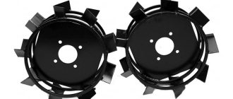
The first ones are made in the form of disks; they are designed to weigh down the wheels or axle of the walk-behind tractor. The discs improve the soil-clinging properties; the weight of one disc is 10 kg.
The latter are produced in the form of a cylinder, which is attached only to the pin of the walk-behind tractor. Thus, burdening its frame, the weight of one such cylinder is 17 kg.
How to do it yourself?
When performing its functions, the hitch for a walk-behind tractor will bear heavy loads, which means that it is necessary to comply with the recommended strength and dimensional parameters of all components of the assembly.
Then the following properties of the coupling device will be ensured:
- guarantee of strong pairing with the walk-behind tractor;
- fastening to attachments;
- guarantee of the declared performance properties of the products;
- acceptable price;
- quality, long service life.
When choosing a modification, you need to check the dimensions of the towing device (towbar) of the walk-behind tractor and attachments (harrow, trailer, plow, etc.).
The specialist’s task is to ensure absolute compatibility of components, ease of use and the ability to quickly configure equipment for a specific task.
The main component of the multifunctional hitch is a U-shaped holder. Through the holes on one side, it is fixed to the motor vehicle using pins; on the other side, a rack of the required attachments is attached to the casing of the device.
Required tools, materials and accessories
There is a certain set of tools that are needed to create a coupling device. Basically, everything that is needed to assemble such elements is available on the farm of everyone who cultivates their own plot of land.
You will need the following tools:
- angle grinder;
- electric drill or drilling machine;
- measuring instruments: square, tape measure, ruler;
- welding machine;
- set of wrenches;
- fasteners (studs, bolts).
It should be noted that in this situation it is extremely important that the holes that will be drilled into the part coincide exactly with the studs and bolts. A gap in diameter is not needed, because it will reduce the operating period of the trailers and canopies used.
At the same time, during the work, it is important to first make holes in the element with the smallest diameter (from 5 millimeters), and then drill them with larger drills (up to 12-16 millimeters, in accordance with the diameters of the bolts).
This method will speed up and simplify this part of the work, while at the same time allowing you to measure the holes as accurately as possible. To create the frame, you can use a channel of the appropriate size, and if it is missing, you can assemble an element from an iron sheet.
A modification of a custom hitch is very practical - such a design will make it possible to connect attachments of different generations, classes and brands. Despite the fact that such a design is not in demand at the moment, we must not forget that various devices will gradually appear on the farm, and the possibility of convenient aggregation of each of them will seriously increase the choice, making it possible to proceed only from the necessary functional features of the equipment.
Blueprints
Assembling a coupling device for motorcycles on your own involves the use of drawing materials. There are quite a few different options, but it is better to take the most suitable one as a basis and adjust it, taking into account the characteristics of your own equipment.
The drawing should reflect the following elements:
- 2 U-shaped parts, equal in all characteristics, but with a different number of holes - in the first 6, in the second 8;
- a housing containing 2 threads with diameters M12 and M16 and equipped with a mounting structure for fixation with one of the units;
- the adjustment element is a handle placed on the body of the element; its structure includes a screw connected to the holder and having a handle for comfort (it is important to calculate the exact direction of the holder - exclusively up or down and so that it does not interfere with the operation of the motorcycle).
Because motorcycles, under any conditions, require pairing with a hitch, you can find out the details of the location of the connection in its present instructions.
Step by step guide
To make a multifunctional connection, you need an extremely flat plane - a special work table. The plan for manufacturing a coupling device for a walk-behind tractor is as follows.
- Make the markings according to the drawing: mark the outlines of the elements on the workpiece.
- Using an electric drill or drilling machine, make holes according to the marks. Make sure they are correct by using a caliper and a pin (bolt) that will be used to fix them. Achieve a suitable hole diameter at which there is no backlash and the fasteners do not jam.
- Weld the connections. It is preferable to use electric arc welding, in which heating occurs exclusively in the joint areas without any harm to the working properties of the steel.
- Assemble the part. Connect the holder and channel with bolts. If the design has a setting tool, attach that too.
- The fasteners by which the coupling device is attached to the walk-behind tractor through the holes in the units must be of the same quality and strength as the device itself.
Let us remind you again that the part is performed so that the versatility of the walk-behind tractor is maximized.
If you have an ideally suited coupling device, it is possible to comfortably aggregate and long-term effective operation of each suspended or trailed equipment, including: adapter, hiller, harrow, plow, trailer, all kinds of mowers, potato planters and any other devices.
And for the reason that the fixation components on different equipment may differ, which usually makes it difficult for them to interact with the walk-behind tractor, the successful design of the coupling device and the ability to configure it solve this problem.
Installation of attachments on motor vehicles
After assembling the part, the main thing is to connect it correctly. The installation techniques are quite simple, but it is important to follow them. In essence, docking equipment to a walk-behind tractor comes down to a rather simple action: you need to make sure that the holes of the coupling device and the hitch match and secure them with bolts or pins. Radial holes make it possible to adjust the position of the connecting device during operation.
Upon completion of installation, it is necessary to tighten the components of the threaded fastening of the device to the motorcycle. Then the attachments are attached.
After the initial aggregation of the devices, final fixation will follow, which must be performed right before starting work. The adjusting elements (bolts) must be loosened, the ideal level of fixation must be found, and then tightened with wrenches.
Depending on the structure, a replaceable threaded pin can be placed on the holder, into which an M16 bolt is screwed.
Harrows
The harrow is designed to mix the top layer of soil (for uniform fertilization, moistening or aerating the soil) and bringing it into a homogeneous state (removes crust on the ground, breaks up lumps, removes weeds). One official harrow model is presented on the official website of the manufacturer of walk-behind tractors Neva.
Harrow BD 850M (husker)
The harrow breaks large pieces (blocks) of soil into smaller ones, thanks to which the soil additionally absorbs moisture and oxygen. These two factors are mandatory for growing crops.
Harrow BD 850M
BD 850 is a disc harrow and is recommended for use in small or medium-sized fields. In this case, the width of the work can be adjusted from 70 to 96 cm.
The harrow is equipped with 8 high-quality steel discs. They are replaceable and, if desired, old ones can be easily exchanged for new ones. The discs are sharpened at the factory using a special technology, thanks to which they do not become dull over a long period of operation.
Discs are installed on the axle. These axles are mounted on heavy-duty Teflon bearings.
The furrow angle can be changed depending on the conditions:
- An inclination of 10° is used for aggressive furrowing;
- An inclination of 15° is used for standard furrowing;
- An inclination of 20° is used for soft furrowing.
If hard rock is being processed and the discs slip, then a weighting agent can be used to sink them into the ground. For this purpose there is a special well-thought-out platform on top.
To achieve maximum furrowing results, two furrows can be used in series. In this case, the first unit dumps the earth inside, and the second outside.
Important Lawn mowers and other garden tools from Stihl
It is also recommended to replace regular wheels with lug wheels.
Installation of the Harrow BD 850M on the Neva walk-behind tractor
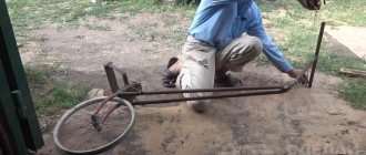
Is it possible to make a harrow with your own hands?
If desired, you can assemble the harrow yourself; there is nothing complicated in this design.
The easiest way to make a toothed harrow. It is slightly less efficient than disk, but the device is much simpler.
All you need is a square tube, teeth and bolts.
It is necessary to cut the pipes and connect them to each other at an angle of approximately 30 °. And at the place where they connect, insert the teeth and secure them with bolts.
To connect to the walk-behind tractor, you can use a regular chain or make a coupling device using a regular metal pipe.
But this structure will often jump out of the ground; it needs to be additionally weighted with something. The ideal solution to the problem would be cinder blocks or any heavy metal structures. But you should not overdo it, since the connecting elements must support the weight of the entire structure.
Video review
The video demonstrates the manufacturing process of such a harrow:
And here is a video of the harrow in action and the result of the work done:
What the owners say
Here are a few opinions from people who have already worked with harrows on Neva walk-behind tractors.
Alexey writes:
“I decided to make the harrow myself, since its design was intuitive to me. Therefore, after thinking a little and collecting information on the forums, I was able to do it without any problems. All that was needed were pins and pipes to attach them. Simplicity is the key to success)"
Specifications
For Zirka hitches in the shortened version, the height of the inner sleeve or the diameter of the hole ranges from 2 to 9.4 centimeters. At the same time, the weight of the structure is 4.6 kilograms. The size of the frame strip is 315 mm.
- This product is distinguished by an adjustment angle and the presence of a rotating mechanism, thanks to which the plow, regardless of conditions, cultivates the soil strictly horizontally, even if the walk-behind tractor moves. The hitch is widely used when it is necessary to adjust the operation of attachments or when uneven surfaces are plowed.
- There is an extended version of the described model on the market. The weight of the structure has increased to 7.5 kg, the internal diameter is 210 mm, and the sleeve has a height of 94 mm. The dimensions of the frame strip are also larger - 520 mm.
- The product is used in cases where it is necessary to adjust the operation of attachments.
- The design used a rotary type clamp. The plow always goes at a right angle and everything is thanks to the bolted connection, while the position of the equipment does not play a role.
- Universal hitches also have a bolt clamp, but they are attached to the equipment using a special adapter. The width can reach 0.9 meters, the maximum weight is 6.6 kg.
- If we consider the triple model, then it is installed on the walk-behind tractor using the front part on the rotary unit. This part must be purchased separately, since it is not supplied with any walk-behind tractor. The width of the described coupling is 900 mm. The mounting plate is 80 mm wide and 120 mm long. The weight of the structure is 7.3 kg.
- If you plan to use a walk-behind tractor as a snow blower, then you won’t find a better U-shaped hitch.
Kinds
It is extremely important to choose a suitable hitch for the walk-behind tractor, since a lot depends on its quality.
It happens: It happens:
- single or double;
- with reinforced structure;
- adjustable;
- universal option.
Its difference from the previous one is greater thickness and length. Thanks to the design, the plow or cutter can sink deeper into the ground.
Adjustable allows the user to set the desired shaft angle. As a result, the attachments are installed at the required level, and work efficiency increases accordingly.
The universal hitch is used everywhere, it can be rearranged for different models. Due to this, the user has the opportunity to adjust the angle at which the attachment is installed. The main role is played by the bolt mechanism.
Precisely for the reason that such a hitch is used when hanging hillers and plows, it can be either double or triple, which means it is not prohibited to connect several working elements at the same time.
Most often, a U-shaped unit is used, which can be made either independently or purchased ready-made. There is also a hitch for sale for the APM adapter, which is necessary when working with a hiller or plow.
It is used on walk-behind tractors:
- "Neva";
- "Oka";
- "Centaur 1080D";
- "MTZ";
- "MB";
- "Cascade".
The product is attached to the rear or front adapter, and then additional equipment such as a plow or potato digger is attached. The design of the product is thought out in such a way that reliable fastening can be ensured through the use of three bolts. When the walk-behind tractor tilts during operation, the plow remains perpendicular to the ground.
For example, in the horizontal plane, the maximum permissible angle is +-20 degrees, in the vertical plane it is 7 degrees more. There is also a coupling option for walk-behind tractors on the market - MK, used for the Krot series plow and the ON-2 hiller. It is used exclusively in this version and in no other way, that is, it is not suitable for other attachments.
The simplest trailer model
To build the structure needed on the farm, you need to prepare:
- Steel pipes 60x30 mm and 25x25 mm;
- Springs and wheels (can be from a Moskvich car);
- Duralumin sheet 2 mm thick;
- Cut of sheet steel 0.8 mm thick;
- Channel No. 5;
- Fastening elements;
- Tools (jigsaw, grinder, welding machine and screwdriver).
- The trailer frame is a one-piece structure placed on a frame grid. To equip it, you need to make two traverses from a 25x25 mm corner, which will act as front and rear cross members, and spars from a 60x30 mm pipe. All elements are connected using five crossbars so that the result is a lattice.
- A simple trailer model with folding sides is a very necessary thing in the household. With its help you can not only transport boxes and bags with harvested crops, but any long cargo
- When arranging the lattice platform, you need to place the cross members and traverses relative to the side members so that small outlets remain. Longitudinal pipes will subsequently be welded to them.
- Four racks are attached to the longitudinal pipes by welding, and strappings from a 25x25 mm angle are welded to the top of them. To equip a trailer with folding sides, the frame of the structure is made separately from the frame. The platform grille is covered with a duralumin sheet, secured with bolts. To cover the sides, you can use thinner metal sheets, securing them to the straps and racks by welding.
- To make a beam, two channels of the same length are inserted into each other, equipping one of the ends of the structure with wheel axles. The finished beam is connected to the side members using springs. To do this, the ends of the springs are put on the bracket axis and the shackle axis, and the central part is welded to the beam with stepladders.
- The drawbar is made from rectangular pipes 60x30 mm. To manufacture a two-beam structure, the front ends of the pipes are joined and welded to the body of the unit’s towing device, and the rear ends with an overlap of 200 mm are welded to the front ends of the side members.
- The trailer is ready. If desired, it can be equipped with brake lights, turn signals and side lights.
Adapters
This is a trolley, the structure of which consists of a seat, a brake, a brake handle, a footrest, a coupling mechanism, and a frame. When using an adapter, you can hang additional equipment on the walk-behind tractor, which will allow you to expand the scope of your activities and perform several functions at the same time. Adapters are usually classified according to:
- type of clutch (steering and with a movable joint);
- type of location (front and rear).
In steering adapters, the articulation between the walk-behind tractor and the equipment itself is very rigid. It can be controlled using a separate steering unit. The adapter wheels can be located either at the back or at the front. In adapters with a movable joint, the angle of inclination in relation to the vertical axis at the joint can be adjusted. They are more difficult to control due to maneuvers with increasing radius.
The front adapters are located at the front of the walk-behind tractor, while the coupling point between them is located at the rear. They have steering and a more complex design than rear adapters. Therefore, front adapters are more expensive. Unlike the front adapters, the rear ones are located at the back of the walk-behind tractor and are attached to it from the front. These adapters can be used effectively when working in the garden, because it is more convenient for the owner of the equipment to monitor the area being processed.
A snow blower is used in everyday life and cannot handle large scale applications. It works by transmitting power from the walk-behind tractor to the attachment through a belt. Snow removal equipment consists of a motor, front blades that shovel snow, and a rotor assembly inside the mechanism.
Seat installation tips
You can make drawings of special devices for a walk-behind tractor with your own hands. From them you can find out that the adapter is attached to the equipment using a single hitch, which is made of 2 parts. The first is needed to connect the equipment, while the other is considered an adjustable adapter between the fixture and the lifting mechanism.
To increase the number of implements used, the adapter can be upgraded with a special double hitch. Such a device for the Salyut walk-behind tractor may also be suitable.
With a ledge of 80 centimeters from the front corner, the seat must be secured to a special frame. Bolts must be used for this work. When the entire system is completed, it needs to be tested for functionality.
Making a Plow
Before creating such equipment, you will have to prepare drawings. In them you can indicate the main components - the ploughshare and the blade.
- For working parts, it is worth taking 3 mm steel, but first the craftsmen recommend working on the removable plowshare. A disc taken from a circular saw will act as a higher-quality material for it. If it is not available, you can take ordinary steel, which is not subject to special treatment.
- The cutting part will be the working part of the scythe, which is hammered on the anvil. The plow must have a moldboard; you can proceed to its creation after completing work with the ploughshare. As a material for this, you can take a pipe (50 mm), the thickness of which will be 5 mm. The blade can be prepared using a gas cutter. First, we cut out the template; at the last stage, the workpiece needs to be finished on an anvil, and then on a sharpening machine.
Reversible plow for walk-behind tractor: do it at home
A universal version of a reversible (reversible) plow is shown in the figure.
The size of the structural elements is detailed in the drawing.
- plowshares (a) made of steel. It is desirable that they be removable for possible sharpening or modernization. The cutting part is processed on an anvil and sharpened. The lower one is designed for cutting into the soil, the upper one turns over the cut layer. The strength of the latter can be strengthened with a corner welded to it;
- form a dump, there are several ways to do this. According to one of them, a steel pipe with a diameter of no more than 6 cm is taken, to which a cardboard blank is attached. There should be about 20 0 between the generatrix of the pipe and the stencil;
- side part of the stand (b);
- spacer plate (c);
- base of the product (d);
- corner (d);
- stand (e).
The diagram shows the assembly sequence of the rotary plow, where 1 is the share, 2 is the side part of the stand and 3 is the auxiliary sheet.
Making a homemade trailer for a walk-behind tractor with your own hands
The technology for creating any machine is approximately the same. First, all the parts are made, then assembly begins.
Housing frame
You need to start by making a frame, to which, in the process of making other parts, you should try them on and see how the entire product is assembled. As a rule, this is a rectangular product with dimensions of about 1500×1000 mm.
Chassis
Experts believe that the most reasonable thing is to take the rear axle from a decommissioned small car, for example, Tavria. Of course, you need to go through, wash and lubricate all the moving elements.
Body, frame trim
A trailer is made so that something can be transported in it. This means you need a small body. The frame is already there, you need to make the sides. They can be made of wood, plastic, or corrugated sheets. Wood is short-lived, plastic has low strength, metal is more expensive, but will last much longer. If the sides are made of steel sheet, then they must be reinforced with stiffeners. Wooden sides must be treated with a special impregnation to prevent rotting. It is recommended to make the tailgate opening.
Do-it-yourself trailer brakes for a walk-behind tractor
Any vehicle must have a brake. And the hitch of a walk-behind tractor and a trailer is a vehicle. Of course, you can’t drive it on city streets, but for your own safety you still need to install a brake. The mechanism shown in the figure below is operated by a foot pedal. When parked, the device is secured with a furniture latch. If possible, you can install real car brakes.
Other details
The most popular “other part” is the mechanic’s seat, and sometimes also the passenger’s seat. The degree of comfort provided depends on the taste and ingenuity of the designer. And another useful detail is a parking stand for the trailer beam. When parked, this device is folded down and the trailer is in a horizontal position.
How to make a two-axle trailer for a walk-behind tractor
To transport cargo over 300 kg, a biaxial trailer should be made. The technology for creating it is the same as for a single-axle one - development of design documentation, selection of materials and suitable parts, manufacturing of parts and frame. Since the vehicle is designed for a large load capacity, the frame must be made larger durable. It will require profile pipes measuring at least 50?50 mm?. The wheel axles are welded to the frame side members. An interesting option is obtained when the walk-behind tractor is placed behind the loading platform. This layout resembles an ATV. During the process of testing and modification, the front part of this miracle machine was equipped with a steering column with all the necessary mechanisms. The result was a self-running stroller. And you can attach a cargo trolley to the back of it.
Tipper trailer for walk-behind tractor
The peculiarity of a dump trailer is that its body is not welded to the trailer platform, but is mounted on a hinge. The center of gravity of the loaded body should be slightly behind the hinge. The tailgate must be folding or removable. The manufacturing technology is the same as for other designs.
How to choose?
In order to choose a tractor towed to a walk-behind tractor, it is necessary to analyze the totality of the qualities of all its components, as well as its compatibility with the walk-behind tractor.
The first thing you need to pay close attention to is the working part of the trailer - the body. It can be made of steel or galvanized metal
The first option is considered more reliable, and the second - more durable. But when choosing a galvanized body, it is necessary to evaluate the thickness of the metal. If it is small, it will not be able to withstand heavy loads. The permissible tonnage can be found out by paying attention to the numbers in the name of the trailer.
When purchasing this equipment, you may also find plastic models on the market, however, it is better not to pay attention to the low price. Such a trailer will not last long due to the low strength properties of the material. You will have to constantly think about how to ensure that the sides remain intact during loading or how not to overdo it with the weight of the cargo.
You also need to think about the frequency of use of this design. The required design of the sides depends on this. If the trailer is intended to be used constantly, then tailgates with a tipper unloading system can significantly save operating time.
You should also learn about the quality of the wheel hubs, since the serviceability of the braking system depends on them. Most often they are produced from two types of material. This is cast iron and steel. The first option will fail much faster, which cannot be said about the second. Strong alloys have become quite durable, durable and reliable.
One last thing worth paying some attention to is ground clearance. When driving through fields and plowing, this criterion is especially important.
The distance from the ground to the cart should not be too small, otherwise, when loaded, the structure may touch the ground. But a greater height is also unacceptable, since loading will be much more difficult.
Taking into account all the parameters, we can say that the best option for a full-size trolley can be a budget option called TM-360, produced domestically. The load capacity of this trailer is 360 kg. One of its main advantages, in addition to its generally satisfactory characteristics, is its temperature tolerance. This device can be easily operated in almost any part of Russia. The design can withstand temperature changes from -30 to +40 degrees.
What to consider when purchasing
- Equipment. For convenience, the trailer and cart for the walk-behind tractor (with the exception of the garden cart) have a seat for 1 person and a footrest. Also, all attachments come with pneumatic wheels, which are designed for easy movement around the site.
- Permissible loads. Carts and trailers are capable of transporting loads weighing up to 500 kg. The plastic garden cart differs from them - its load capacity is 50 kg. The maximum operating speed for the equipment is 25 km/h.
We offer carts and trolleys for walk-behind tractors throughout Russia: Moscow, St. Petersburg, Yekaterinburg, Chelyabinsk, Nizhny Novgorod and many other cities with delivery and guarantee, call! You can find out detailed information about the conditions and cost of delivery from our managers.
The assembly of a passenger trailer occurs in accordance with the drawing and consists of several stages:
- Frame assembly. This part of the product is a load-bearing part, and the durability of the trailer will depend on its strength. To do this, the pipe or profile is cut to size and welded together. The resulting rectangle is checked for accuracy and evenness of the assembly. Additionally, a stiffener is provided, since the rectangular frame is unstable under load.
- Connection point to the vehicle. When making it, you need to keep in mind that the shorter it is, the faster the trailer will respond to vehicle maneuvers. The optimal length of the connecting part will be 1.5-2 m. The same material is used for its manufacture as for the frame. Before starting welding, the correct placement of the parts to be joined is checked so that the coupling is in the middle. To ensure that the connecting part does not break under load, safety cables are mounted and welded at the bottom of the structure.
- Coupling. Serves to attach the connecting part of the trailer to the vehicle. Can be mounted either with bolts or welding. The first method is less reliable, but can be easily dismantled. The welded assembly is durable, but may require a gas torch to remove it. For bolted connections, samples of the eighth strength class are selected.
- Axle assembly. According to general rules, the axle is mounted at a distance of 40% from the rear side of the trailer, that is, it is slightly shifted from the center to the rear. Fastening occurs using a bolted connection, a frame is installed on it, and also connected with bolts.
- Stabilizing jacks are a desirable but not required part of the structure. They ensure the trailer is level when driving. The best option for their placement is in the corners of the frame.
- Flooring on the side walls. It is made of metal, plastic, wood or other material, depending on the cargo that is planned to be transported. It is bolted, after which the sides are mounted on the frame. The corners are reinforced with metal corners.
- Finishing. They did it and the nodes are painted, after which the power connection route for electrical appliances is drawn. Headlights, lanterns and reflectors must be installed. Connection to a single network is made using the towbar socket. If necessary, a homemade trailer is equipped with a braking system.