Angular gearbox: device, purpose and principle of operation
Gearboxes are installed on various mechanisms.
These can be large ships and a small boat; mechanisms for agricultural machinery and cars are equipped. Inexpensive units are equipped with one-piece, maintenance-free gearboxes. Therefore, you can extend the life of your irreplaceable assistant with your own hands at low cost. Powerful devices and small gearboxes have the same structure and operating principle.
Kinds
Depending on the type of transmission used in the gearbox, converters are divided into several types. Different devices are used in mechanisms of different fields of activity.
Chain
The name is due to the design of the gearbox, which is based on a chain as a transmitting element. There may be more than one in one device. The movement is provided by sprockets, the small one is the leading one, the big one is the driven one. The principle is similar to the system on a bicycle. Productivity and reliability depend significantly on the quality of materials used to manufacture the main driving parts.
Among the negative aspects, the need for regular maintenance should be highlighted: chain tightening, lubrication. Unlike a belt drive, a chain drive does not allow slipping and lasts longer.
With reverse
The reversing mechanism provides the equipment with the ability to reverse. In this case, the reverse rotation clutch is installed between the bevel gears, which are located on the main shaft.
Belt
The simplest gearbox available on the market is of the belt type. As a rule, budget gearbox models use just such a device. The belt serves as a transmission element that is attached to the pulleys. Under heavy loads, the belt slips or breaks.
Belt converters reduce the aggressive effect on the power plant, reducing jerking. In addition, their design is simple and repairs are easy.
Among the minuses, unfortunately, there are more factors.
- At high temperatures the belt stretches. This is what reduces grip.
- Rapid wear and tear.
- Belt drive rupture due to kinks or twists.
- As the speed increases, the belt begins to slip.
- The pulleys must be in the same plane.
Gear
Gear reducers are most often used in engines of heavy equipment. The transmission consists of a gearbox, differentials and regulator, gears and belts. The design of the device is simple.
A gear transmission contains bevel or spur gears. Due to the fact that several of them can be placed on one shaft at once, the dimensions of the converter are reduced.
Among the advantages, one can also highlight the quietness of the engine on this type of gearbox.
Worm
The worm gear inverter features long service life and high reliability. The design is considered not very complex and requires qualified maintenance. The worm gear is already angular. In addition, it has a reverse, which allows the equipment to move not only forward, but also backward.
The gearbox got its name from the presence of a special worm gear in its composition, which moves along a screw having a trapezoidal four- or two-start thread. By varying the number of teeth, you can change the rotational speed. All components are made of anti-friction steel, which is characterized by increased strength.
The converter consists of only two main components. In addition, it is quiet and smooth.
Angular
One of the most efficient and reliable gearboxes. Therefore, it is used to equip production machines and equipment operating under heavy loads. This type of converter is also actively used in the automotive industry.
The angular gearbox ensures the connection of the engine with the transmission, which is designed for chain drive
Please note that the magnitude of the load will depend on the quality of lubricants and temperature conditions
Downward
The goal of a reduction gearbox is to reduce the number of revolutions while increasing power. This is achieved by using a gear system. As a rule, modern converters of this type are equipped with an air cooling system.
Main types, their purpose
A gearbox is equipment that allows the use of an engine in the design of various units. Rotation from the motor is transmitted to the car wheel and boat propeller. In this case, the force increases, with a decrease in the rotation of the motor shaft.
In the household, walk-behind tractors and cultivators are most often used. According to their design features, they can be installed:
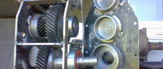
- Gear mechanism. Bevel or cylindrical gears are pressed onto the drive shafts. This design allows them to be used in direct transmission of rotation from the engine. Can be used as an angular gearbox for a walk-behind tractor, while the design uses a bevel gear.
- The device is gear-worm. Most often installed with a vertical engine crankshaft. A gear with a certain number of teeth and a worm screw with a certain thread pitch is a schematic description of the type of device. The main feature is the transmission of rotation of the engine shaft at a right angle.
- Chain device. The shafts are equipped with toothed sprockets. They are wearing a special chain, with the help of which torque is transmitted from the motor. For good performance, the chain is tensioned using a tensioner roller.
- Belt device. Rotation is transmitted using belts. Pulleys with grooves for belts are pressed onto the shafts, and the belt is tensioned using a tension screw.
Most often, in equipping the angular gearbox of a boat motor, walk-behind tractors and other mechanisms, a chain, gear or gear-worm gear is used. Previously, the main one was the belt system; due to breaks, the belt slipping off the pulleys, its operation was considered unreliable.
To make a homemade bevel gear, you need to know its operating principle and how to make them at home.
Equipment
The converter can be collapsible or non-dismountable. As a rule, budget modifications of walk-behind tractors are equipped with the latter option. Their difference is in less expensive parts that cannot be replaced. If it breaks, you will have to replace the entire gearbox. Manufacturers determine the service life of such models from one to two seasons, no more, provided that the device is used correctly.
More expensive equipment is equipped with a collapsible gearbox, which can be repaired by replacing failed components. Therefore, the service life increases significantly.
The converter package includes the following items.
- Frame . Depending on the type of gearbox, it may be dismountable or not.
- Rotor shaft , which provides torque.
- Gears of different sizes.
- Chain or belt depending on the type of gearbox.
- With chain transmission, movement is carried out using sprockets - toothed disks .
- With a belt drive, the mechanism is equipped with pulleys onto which the belt is placed.
- Bearings . Since all the parts rotate, it is necessary to reduce friction and ensure that the elements rotate freely. The bearing is designed to cope with this task.
All parts are located inside the case. In addition to the standard set of components, elements for lubricating bearings, for example, an oil pump or a cooling device, can be added inside the device.
Gear housing
This is the main part and the alignment of the shafts and axles installed in it, and the gaps between the gears depend on its correct manufacturing. In industrial production, the body is cast from metal. It is impossible to make such a case on your own, without equipment, so if you make it yourself, there are 2 options:
- select a ready-made case from other equipment;
- make a homemade steel body by welding and bending metal.
In the second method, the deformation of the structure during heating should be taken into account. Leave small tolerances in the places where the bearing is secured to the shaft or axle, as well as in the place where the oil seal is installed. You should not weld the bearing to the housing - this will affect its operation and problems during replacement. To make it easier, you can select a pipe of suitable diameter, weld it to the body and press in the sliding supports.
To make repairs and maintenance easier, the housing should be closed with a protective cover. At the top, a hole is made with a plug for filling in new transmission oil; at the bottom we place a plug for the waste drain.
Self-manufacturing of the gearbox - simple about the complex
Each of the listed types of converters has its own disadvantages. Therefore, in order to repair the walk-behind tractor gearbox as rarely as possible, some farmers prefer to equip their equipment with homemade converters. A self-made structure often turns out to be of higher quality and more reliable. To work you will need:
- Phillips and flathead screwdrivers;
- Hacksaw for working with metal;
- Pliers;
- Vise;
- Welding machine.
First you need to weld the body. For this you can use stainless steel plates. Gears and shafts will also be needed for the job. You can “borrow” them from the Druzhba chainsaw. In this case, you will need to drill a hole inside one of the tool shafts. On the opposite side of the gearbox it is necessary to install a second shaft, and after it - bearings and a cage. The output shaft of the device is attached to a pulley. After this, the finished device should be placed in the previously welded housing and machine oil should be poured inside.
The made converter is connected according to the same principle as the standard gearbox. As you do this, pay attention to the position of each gear. The elements should not be skewed, and their teeth should have perfectly straight ends without kinks or other deformations.
Finally, you will need to test the converter. We advise you not to load it immediately after creation. To begin, stretch the wound-up walk-behind tractor along the ground - let the elements of the converter connect and establish interaction. Only after this can the equipment be used for its intended purpose.
Shaft and axis of the device
The shafts and gears are keyed and splined, and they rotate together. When equipped with an additional gear that reduces or increases the operation of gearboxes, it is necessary to install the axis on which it rotates. To prevent displacement, emphasis is placed. Shafts can be selected ready-made; if they are manufactured, steel should be used grades St-10 to St-45. Brand St-45 is most suitable for these parts due to its qualities.
Walk-behind tractor and reverse gearbox for it
The clutch is located strictly between bevel gears, freely located on the main shaft.
This is how the reversing circuit in the gearbox is presented, which, if you look at it, is not too complicated. It only clings to the splines in the gears. This is what allows her to change the direction of the spiral-shaped gear. The cam, or fork, is represented by the clutch itself.
A reduction gearbox is a device that is designed to convert torque. There are worm, planetary and combined modifications. The engine with gearbox is capable of operating at high speeds. The standard model consists of a shaft, pushers and gear. If necessary, you can make a step-down device yourself.
Gearbox sliding bearings
The bearing facilitates the rotation of the shafts, removing the friction force through its work. You should remember about the correct selection of this part and proper installation. The sliding support must fit into the seat firmly and forcefully to prevent rotation. It is better to use closed parts. Before installation, it is better to remove the cover and fill the balls and internal support with new grease. When using helical gears or a worm gear, the best option would be to install roller or angular contact ball bearings.
How to maintain motor cultivators yourself (at home)
Servicing a cultivator at home is a completely doable task; it can be done by those consumers who have at least a little technical knowledge and skills in stock.
By its design, a motor cultivator is not something unimaginably complex. It has an engine, gearbox and frame. These are the main parts. There are also handles for holding during operation and a control system. Now let’s take a closer look at each part of the mechanism and understand their service.
The frame is the most durable and therefore reliable part of the cultivator. The motor and gearbox, as well as control and carrying handles, are mounted on it. It is advisable to put the frame in order after each use and remove parts of the soil from it, then the material will deteriorate much less. Care should be taken to install protective shields on the frame. Thanks to them, you will be protected from possible injuries, for example, a pebble that accidentally bounces off the cutter or a suddenly broken gear belt. Even during operation, the earth from the cutter flies onto both the frame and the engine with gearbox, and this is fraught with damage.
The gearbox in a cultivator can be worm or chain (in walk-behind tractors it is gear-type). Any gearbox uses liquid lubricants
To ensure trouble-free operation of the gearbox, it is necessary to pay attention to the joints on the housing so that oil does not leak; if such a problem exists, it is worth tightening the fastening joints. Do not forget to change dirty oil to clean oil every two seasons.
After using the equipment, it is necessary to clean the gearbox and its breather (a unit for removing excess pressure into the atmosphere). The equipment must be moved vertically, then lubricant will not leak out of the gearbox (through the breather).
The engine transmits rotation to the chain gearbox using a belt drive, so keep an eye on its belt; as soon as you see hanging threads or cracks on it, change it without delay. And when changing the belt, also clean the grooves (with gasoline) on the belt seating pulleys. We recommend installing a cover on the transmission itself for protection.
It is better to work in dry soil conditions, because working with wet soil greatly increases the load on the cultivator, and this negatively affects the operation of the worm gear. If we take into account the fact that in motor-cultivators with such a gearbox the frame is the housing from the gearbox, then the cost of subsequent repairs can be equal to the price of a new unit.
The engine is one of the main parts of the cultivator, one might say its heart. Mostly four-stroke engines (gasoline) are mounted. They are assembled in a special way to ensure easy access to all important control systems (requiring frequent maintenance): fuel system, lubrication system, ignition and cooling systems. Engine maintenance is the most important point, so we will look at it in more detail below.
Pens
Pay attention to the handles that you hold on to when driving, their rubberized linings wear out over time, so change them in time or strengthen the old ones with electrical tape
Cable. All control devices must be carefully adjusted; if they cannot be adjusted, then you need to check the integrity and reliability of the drive connection (mostly a braided cable). If the cultivator is located in places of moisture, the cable may well lose the ability to move in the braid. Then the cable is replaced with a new one or the braid is disassembled, cleaned of corrosion and the cable is lubricated.
Gears
By means of a gear engagement of two gears, rotation is transmitted from the engine shaft to the gearbox. Gears are cut on special gear cutting machines, so you should make a calculation and buy. The final placement of units and the quality of equipment operation depend on this choice. The number of teeth and gear diameter are two major factors in equipment design.
During installation, it is necessary to maintain the distance between the gears, protecting them from breakage. You should also ensure that the surfaces and teeth are lubricated with gear lubricant. It is poured to the level of the top of the gear, all other parts are lubricated by splashing oil as the gears rotate.
Types of gear units
The transmission of rotational motion from the motor shaft to the actuator shaft can be carried out by direct connection of the axes, if the speed and power of rotation of the engine are acceptable for operation, and the axes of the drive and driven shafts coincide. Such cases are extremely rare, and with several attachments for different purposes, direct transmission absolutely cannot be used. To match the speed and power of the drive and driven shafts, 4 types of mechanisms and their combinations are used. Main types of gears:
Safety clutch
It is installed to prevent gearbox destruction during emergency jamming. Can be made in the form of friction clutches or a pin.
You can complete the work of self-assembly and selection of the necessary parts by reading the instructions and recommendations on the Internet.
In conclusion, it is necessary to recall the importance of carrying out routine maintenance of any gearbox. Timely lubrication, monitoring the condition of the housing and the oil level in the gearbox will increase the reliability and service life of your equipment.
Most often, it is used to reduce the rotation speed. For example: a boat cannot reach the speed its engine produces. Therefore, an angular gearbox is installed that reduces the propeller speed.
A correctly selected and high-quality bevel gearbox protects your equipment from overloads during operation. Maintenance and timely repair work will allow the equipment to perform its task without accidents and major repairs.
Varieties
The gearboxes with which walk-behind tractors are equipped seem identical only at first glance. In fact, these devices can be divided into three groups. The differences lie in the design features of the gearboxes. Let's get to know the representatives of this family in more detail.
Angular
Angle-type gearboxes are elementary structures that serve to connect the transmission to the power plant of the unit.
The structure of this node looks like this:
- Mechanism body.
- Belt drive pulley with fastening.
- Rotor shaft.
- Flange complete with mounting and bearing.
- Washer and fixing key.
Gear
This is a more complex mechanism, which is impossible to recreate at home without special skills and knowledge.
Gear reducers are called reduction gearboxes. Thanks to its design features, the mechanism reduces the engine speed, simultaneously increasing the power output of the walk-behind tractor.
Such gearboxes have a long service life, so they are suitable for performing various jobs, and do not suffer mechanical damage even under peak loads.
Reversible
This mechanism is based on a clutch that moves freely between bevel gears.
Such gearboxes enable the walk-behind tractor to move in reverse, which has a positive effect on the maneuverability of the equipment.
However, this comes at the cost of reduced performance and maximum speed. Therefore, each farmer decides independently whether to install a reversible gearbox or not.
Gearboxes installed on walk-behind tractors from different manufacturers have virtually no design differences. Therefore, disassembling the unit and replacing failed parts will not cause difficulties.
Why use a bevel gear?
A mower is being made for a mini tractor; there is a need to change the direction of the drive shaft by 90 degrees, i.e. you need a bevel gear. Or no reduction at all, or with a slight reduction. What common things can it be used for? It won't work with a grinder. The rear axle of the Ural motorcycle lowers greatly. Maybe agricultural machinery has something like this as standard? Does anyone have experience in manufacturing such gearboxes using automotive differential gears?
I saw something similar on a combine harvester, on this thing in front)) well, where are the knives. The combine in the village is some kind of ancient, either Neva or xs. in general, look for angular gears, they are available in the factory version
off: and here the oil tank builders crawled
Well, if you install a bevel gear with a large reduction, and then increase the speed.
I already thought. but as in the joke: this back and forth annoys me. I would like to avoid unnecessary details... this has already happened a couple of times, you get wiser and wiser, and then you come across a simple solution. Unfortunately, a person’s horizons are not limitless. Right now I’m already thinking about making a turn from two cardans with an intermediate support.
90 degrees and cardans, well, I don’t know, will they work normally?
SerJen wrote: 90 degrees and cardans, well, I don’t know, will they work normally?
turns out 2 at 45 degrees
I saw such a gearbox with a slight reduction in an agricultural machine for sorting potatoes
2Dred Did you decide to come up with a mower for a Lambordini?
Dred wrote: . you need a bevel gear. Or no reduction at all, or with a slight reduction. What common things can be used for. Maybe agricultural machinery has something like this as standard?
On 40s, a drive pulley with an angular gearbox is placed on the rear PTO. In teeth 22-12, if I'm not mistaken..
Ged wrote: Did you decide to come up with a mower for a Lambordini?
Yes, my phacelia is blooming, so in a couple of weeks I will need to mow it. Last year, two days of three hours each with a lawn mower did not inspire me; my hand then went numb and did not come off for a month, but this year the area sown has increased.
I tried to find a standard one from the 40, but either the working unit is sold assembled, or it is no longer a gearbox. and the trash...
It turned out that the Ural chainsaw supposedly has an angular gearbox... can anyone explain anything about this? I know where many of these saws are lying without engines.
“Friendship”, “Ural” Electron”, Angular gearbox, gear ratio - 1:2 (I also know where many of these saws are. In the topic “Friendship saw”. There are a lot of them!)
Dred wrote: that the Ural chainsaw supposedly has a bevel gear...
Yes, not supposedly, but it really is worth it, but the gear ratio is about 13
And if you look at the gearboxes of outboard motors? There are so many of them lying around everywhere now. Not very step-down (and if you turn it on the other way around, then step-up), in addition to reverse
there is a gear ratio of approximately 1.5
I’m already thinking about “putting the reduction gear in reverse.” I can only take power from the camshaft, and starting occurs through it, i.e. revolutions from 500 to 1500. For a rotary mower, judging by the characteristics of factory mowers, speeds from 2500 and above are needed. so a 1:3 gearbox will be fine. What do you think about using flanges from a household concrete mixer in a mower? the shape of the disc, there is a seat for the bearing, the diameter is about 500 mm, the price tag is humane and is always available in spare parts.
Here's the device, we'll torture it...
A mower is being made for a mini tractor,
show me what you came up with, maybe we can help you with advice
Yes, I rarely ever make things up, so I decided to stupidly steal the design of an MTZ or forty mower, i.e. a tire made of a channel, on top of it are three flanges of a concrete mixer, we sculpt 3 knives from spring steel onto them, the drive is first with a cardan based on the Ural motorcycle joints through an angular step-up gearbox and then with a motorcycle chain on the sprockets of the flanges, all three are one chain, so the axles of the flanges are not on a straight line, but in a triangle, well, you’ll also have to attach a spring-loaded tensioner. All. The problem is not to invent, the problem is to adapt various standard crap in order to at least bother with a lathe and milling machine. and so that it would be cheap, i.e. crap not from Lexus, it was right now I can throw in a little drawing
Model overview
In order to get some idea about walk-behind tractors with a power take-off shaft, it is necessary to become more familiar with the characteristics and features of some models.
NEVA MB-Compact S-6.0
The walk-behind tractor of this model is considered a real find for adherents of professional equipment. The unit has great functionality despite its compact size. Almost the entire range of mounted implements can be connected to the PTO, from a plow to a snow removal rotor.
The manufacturer specifies the following technical specifications:
- weight – 70 kg;
- power – 6 l. With.;
- low noise level;
- quick start and flawless operation in cold weather;
- cultivation depth up to 20 cm;
- high engine life;
- working width – 86 cm.
In addition, some modifications of the Neva can be equipped with an electric starter.
Agate (Salyut) 5P
The walk-behind tractor is used mainly for agricultural work on small farms. With the help of additional accessories, this unit can be used as a small tractor.
Has a downshift function. When transporting cargo weighing up to 500 kg, it reaches a speed of 10 km/h.
Technical data:
- weight – 78 kg;
- power – 5 l. With.;
- plowing depth 25 cm;
- adjustable processing width up to 90 cm;
- The steering column is equipped with two position switches for comfortable control.
Belarus 09N-01
The model is designed for versatile soil cultivation over an area of up to 5 hectares. The unit is distinguished by its unpretentiousness to working conditions and reliability. Thanks to the mass, wheel traction with the soil surface and excellent control are ensured. Belongs to the severe type.
The following characteristics can be noted:
- unit weight – 176 kg;
- developed power – 9.38 liters. With.;
- working width is adjustable from 45 to 70 cm;
- number of gears – 4/2;
- load capacity – 650 kg;
- speed up to 11 km/h.
Profi 1900
The walk-behind tractors were specially developed by German manufacturers for carrying out agricultural operations in areas with heavy soil and poor traffic. Thanks to its power of 14 horsepower, this machine is capable of providing easy working conditions where considerable effort must be made with a conventional walk-behind tractor. For evening work, these models are equipped with a front headlight.
Attached Specifications:
- walk-behind tractor weight – 178 kg;
- power – 14 l. With. (in some models up to 18 hp);
- gripping processing width – 80-100 cm;
- plowing depth – 15-30 cm.
In addition, the walk-behind tractor is equipped with a cold start mechanism and a vibration damping system.
Chinese agricultural machinery mainly differs from other brands in its low price. It is good if cost reduction is achieved by increasing the quantity of products. But sometimes manufacturers from this country reduce the price of goods by installing low-quality components.
One way or another, it is worth considering the most popular models.
Forte 105
Positioned as a multifunctional unit for performing agricultural operations on plots with a total area of up to 1.5 hectares. Used for cultivation, harvesting root crops, sowing seeds and many other tasks. The walk-behind tractor is able to withstand high loads for a long time.
Some technical data:
- average unit weight – 105 kg;
- power – 7 l. With.;
- processed width – 105 cm;
- processing depth – 35 cm;
- developed speed – 8 km/h;
- loading weight – 350 kg.
Weima WM1100BE
The walk-behind tractor, made according to Western standards, belongs to the heavy class units. The powerful engine is capable of fully providing high-quality functionality and completing all assigned tasks. The presence of a power take-off shaft allows the unit to operate with implements for various purposes throughout the year. This modification has an electric starter, which makes starting easier in extreme cold.
Characteristics:
- unit power – 9 l. With.;
- weight – 140 kg;
- processed depth – 30 cm;
- working width – 80-130 cm;
- load capacity – 300 kg;
- developed speed is 11 km/h.
You will learn how to make a power take-off shaft in the next video.
How to make a gearbox for a walk-behind tractor with your own hands
Making a gearbox for a walk-behind tractor with your own hands is a difficult and at the same time interesting task. This is one of the important mechanisms, without which the operation of garden equipment using a walk-behind tractor is unthinkable. Its main task is to reduce the speed of the drive shaft and at the same time increase or decrease the torque to the drive.
You can buy a transmission mechanism for your walk-behind tractor in a specialized store, but it is wiser to assemble the gearbox yourself, taking into account all the technical characteristics of the engine. This will be the best option, since when designing a mechanism for a specific power plant, an individual calculation is made, which will simplify the task of pairing it with the engine.
When starting to manufacture a gearbox, you need to clarify which type of mechanism is preferable for your walk-behind tractor. This depends not only on the power of the engine, but also on its layout, as well as on the level of complexity of the tasks assigned.
Final drive device
The design of the final drive is so simple that you can assemble it yourself. The basis of the mechanism is a gear that fits onto the splines of a standard drive. The second, driven gear rotates the wheel. To ensure that the direction of rotation does not change, intermediate (parasitic) gears are installed.
Typically the driven gear has more teeth than the drive gear. This allows you to increase the gear ratio and, if desired, equip the car with larger diameter tires.
The same principle applies to heavy tractor gearboxes such as T 170 or truck gearboxes, which are equipped with KamAZ or MAZ commercial vehicles. The only difference is that for tracked tractors and other equipment, the torque is transmitted not to the wheel hub, but to the track sprocket.
If necessary, repairs to the final drive can be done with your own hands. In most cases, to eliminate noise and vibration, it is enough to replace auxiliary elements: oil seals, floating seals, bearings, etc.
Types of gearboxes
The design of any converting device for a walk-behind tractor (gearbox) consists of a set of motion-transmitting shafts or gears of different diameters, enclosed in a durable housing.
Converting devices are divided into several types according to the type of transmission:
- chain;
- belt;
- gear;
- worm (gear-worm);
- combined systems.
For chain-type gearboxes, rotation transmission is provided using a chain and sprockets of different sizes, which are installed on rotary shafts. The operating principle of a belt mechanism is similar to a chain mechanism, but instead of sprockets and a chain, pulleys and a belt are used.
Inside the housing of the gear reducer there are shafts with gears mounted on them, having straight or oblique teeth. Gears transmit rotation from the engine to moving parts. Bevel gears are used in angular mechanisms for heavy walk-behind tractors.
Types of gearboxes
These devices differ in the type of torque transmission.
- Worm gearboxes. The transmission system of these devices contains a worm gear, which allows not only to significantly reduce the speed of the working shaft, but also to change the direction of rotation. The gearbox shaft at the output of the device is usually located at right angles to the input shaft. This feature of worm devices allows the engine to be placed most compactly together with the torque-transmitting mechanism. The gear ratio of this type of gearbox can be up to 1 to 100 or more;
- Gear reducers. Gear mechanisms for torque transformation are often used in units in which it is necessary to implement a different gear ratio between the input and output shafts. A gearbox of this type can be made with one transmission mechanism, or using several gears with a significant gear ratio. The teeth in such devices can have different shapes, but the quality of processing of such parts must be the highest;
- Hydraulic gearboxes. Such devices are installed between the pump and hydraulic mechanisms. A hydraulic gearbox is used for the same purpose as mechanical ones - to reduce the transmitted energy or rotational speed;
- Geared motor. This system is also used for torque transformation and is a gearbox and motor combined in one housing. The most common are gearmotors operating on electric traction. In this case, it is possible to significantly reduce the size of the gearbox and increase the efficiency of the device;
- Planetary gearboxes. The transmission system and planetary type gearbox circuit is a type of gear mechanism, but due to the originality of the applied method of transmitting torque, it can be considered a separate type. Such mechanisms are compact and very reliable in operation, but require precise calculations during production. The teeth of planetary gearboxes must be tightly meshed with each other, but easily set in motion.
The working parts of gearboxes must be lubricated to reduce the coefficient of friction and power loss. The method of applying lubricants depends on the type of gearbox and the power of the transmitted energy. If the transmission system does not operate at high rotation speeds, then a single application of lubricant to the working surfaces during the entire service life is sufficient. For powerful devices, a special system of forced supply of lubricating fluid is used, followed by cooling and cleaning.
Non-separable products, as a rule, operate at low power levels and in those areas where the device is not required to operate in harsh conditions. Gearboxes that are used to transform large capacities are located in a casing of a collapsible design, which allows, if necessary, to carry out scheduled or emergency repairs and adjustments of the mechanism.
The gear housing can be made of various materials. The selection of material depends on the operating conditions and power of the device. The gearbox for low-power household devices can be made of high-strength plastic or aluminum alloy.
Types of mechanisms
According to the method of operation and action, all transforming mechanisms for walk-behind tractors are divided into several types:
- angular;
- downward;
- reverse with reverse speed (reverse gearbox);
To redirect rotational energy from a vertical drive to a horizontal plane, an angular gearbox using bevel gears (bevel gearbox) is used.
Reducing the number of revolutions and increasing the power of the drive mechanism is provided by reduction gearboxes, or creepers for the walk-behind tractor. They are considered the most reliable for operating a diesel or gasoline air-cooled walk-behind tractor. This allows them to be used for particularly difficult work - for example, plowing heavy soil or harvesting potatoes using a potato digger.
Types of gear units
The transmission of rotational motion from the motor shaft to the actuator shaft can be carried out by direct connection of the axes, if the speed and power of rotation of the engine are acceptable for operation, and the axes of the drive and driven shafts coincide. Such cases are extremely rare, and with several attachments for different purposes, direct transmission absolutely cannot be used. To match the speed and power of the drive and driven shafts, 4 types of mechanisms and their combinations are used. Main types of gears:
The worm gear is structurally limited by the speed-reducing function; the rest can be used in both downshifts and overdrives. In addition, such a gearbox always has a driven axis perpendicular to the drive shaft. This scheme is called an angular gearbox. In addition to the worm gear, you can change the direction of the axis using a spatial planetary mechanism. Belt and chain drives keep the driven axis parallel to the engine axis. In simple devices, reverse is possible only when the rotation of the engine changes.
Motoblocks use engines with a high number of revolutions per minute, which can be verified in the product data sheet. This means that you need to make a gearbox with your own hands to reduce the speed, and it is better to choose what type of homemade gearbox for a walk-behind tractor, knowing the characteristics of each type.
How to make a homemade gearbox for a walk-behind tractor
To independently assemble the converting device on a walk-behind tractor, you need to stock up on the following tools:
- calipers and metal ruler;
- a set of screwdrivers of different sizes, including an oblique one;
- pliers and wire cutters;
- metal saw;
- electric drill with a set of metal drills;
- vice;
- hammers - large and small;
- rubber gaskets.
If you decide to assemble the gearbox for your walk-behind tractor yourself, be sure to make an approximate calculation. This will help determine, at a minimum, the gear ratio and type of converter you need.
Also, using preliminary calculations, you can estimate the dimensions of the future transmission device.
To make the correct calculation, determine the parameters of your engine. For calculations it is necessary to clarify several data:
- Engine crankshaft speed. However, this value is not constant: if you “add the gas”, it will increase significantly. Therefore, calculations are based on the base - the number of idle speeds plus 10%.
- Estimated number of revolutions for the suspension axle. It is calculated taking into account the diameter of the wheels to determine the run-out per full revolution. Based on this, you can calculate at what speed the axis should rotate in order to ensure the most comfortable speed of movement of the walk-behind tractor. This is on average from 3 to 5 km/h.
Let's take a simple example: the engine power at idle, taking into account an increase of 10%, is 600 rpm, and to ensure a speed of 3 km/h, a rotation speed of 200 rpm is required. Therefore, the design gear ratio is 3:1. In other words, to reduce the rotation speed of the axle by a factor of three to ensure a travel speed of 3 km per hour, the torque increases three times.
Step-by-step instructions for assembling a chain gearbox
If you have certain skills, you can make any type of gearbox with your own hands, but the easiest way is to assemble a small-sized mechanism with a chain drive. Materials for it are easier to find and are reliable in operation.
To make a homemade chain mechanism, stock up on the following spare parts and materials:
- sprockets with the required number of teeth;
- driven shaft;
- cylindrical and eccentric bearings;
- protective casing;
- fasteners for connecting parts of the casing;
- chains with the required number of links.
When assembling a gearbox of any design, you cannot replace bearings with bushings. Distortions between the driving and driven parts are unacceptable.
You can use an old gearbox housing of a suitable size as a protective casing, drilling holes in it for mounting.
- The manufacture of a homemade gearbox for a walk-behind tractor begins with securing the drive sprocket to the output shaft of the engine. To secure it, you can use a key or flange. Depending on the design of the output shaft, even spot welding can be used.
- The driven shaft should be machined. The sprocket is fixed on it in the same way as on the drive shaft.
- A more reliable way is to make a shaft from two axle shafts, at the ends of which flanges are machined. The driven sprocket is secured between them, fastening the entire structure with bolts. In this option, the second stage sprocket will be secured more accurately and reliably.
- To protect the gear mechanism from dirt and mechanical damage, it is placed in a protective housing, which also serves as a reservoir containing liquid lubricant for moving parts.
- Sockets are drilled in the protective housing (crankcase) for installing support bearings. The driven shaft is mounted on cylindrical bearings, and the drive shaft is mounted on eccentrics. By changing, due to its design features, the position in the seat within a radius of 15°, the eccentric bearing also changes the position of the drive shaft, thus adjusting the chain tension.
It is necessary that the teeth of the sprocket mounted on the driven shaft are immersed in lubricating oil. When the shaft rotates, all components of the chain gear are uniformly lubricated.
- To ensure the tightness of the crankcase, oil seals and sealing gaskets are installed along the parting line and in the bearing seating areas. If standard gaskets are not suitable, then you can use a special low-resistant sealant.
Gearbox manufacturing process
First, the parameters of the power plant are calculated. The crankshaft speed can be found in the technical specifications.
This is the first quantity required to perform the calculation. The value is not constant, with the addition of “gas” the number of revolutions increases. Basic value: idle speed +10% .
Next, the suspension axle revolutions are calculated . Knowing the size of the wheels, it will be possible to calculate the amount of run-out per revolution. The number of axis revolutions is calculated to ensure a comfortable speed - 3-5 km/h, which is the second value for design.
For example, idle speed +10% is 600 rpm. The required wheel axle speed for 3 km/h is 200 rpm. So, the gear ratio should be 3:1 . The rotation speed of the axis is reduced by three times in relation to the speed of the motor shaft, and the torque increases accordingly by three times. Gearbox types:

