How to make a hoist with your own hands - Metalworker's Guide
Making a hand winch: instructions and video
The winch is one of the oldest devices that facilitates the movement of heavy objects, invented by man much earlier than he knew the laws of physics.
The principle of operation of the winch is based on the rule of leverage: by applying minor forces to the handle, you can move and lift quite heavy objects. Winches and hoists are widely used on the farm for lifting building materials, dragging loads, and even for plowing land.
Winch made from a cable and a piece of pipe
A version of the simplest winch, which can be made literally from scrap materials and in a few minutes, is popular among car enthusiasts. This design is a cable rigidly attached to a piece of pipe placed on an axle. The axle is driven into the ground or secured in some other way. Any lever is slipped under the bottom turn of the cable: a shovel handle, a pipe, a strong pole. By rotating the lever so that the cable is wound around the pipe, you can move a fairly heavy object, for example, a stuck car. This device cannot be called a full-fledged winch, but it performs its functions.
Where is it used?
Initially, hoists were used in production and warehouse facilities. Later they found wide application in auto repair shops and loading and unloading areas.
We recommend: Quick-release corner clamp for welding
Over time, hoists have not lost their relevance - on the contrary, they have become even more in demand.
They are widely used in garages and home workshops, as well as on construction sites.
Worm worm hoists - a compact strongman
In addition to these main types of manual hoists, there are also others. Lately, worm gear hoists are often used. To operate, they are hung stationary or a mobile “cat” is used. This is convenient for moving loads horizontally; such hoists can move along I-beams. There are a lot of models of this type of device. They are used for lifting or holding loads in a raised position; they are also suitable for moving. Everything happens along a special suspended track made of I-beam profile.
Their advantage is that work can be performed in small spaces, and the distance between beams and loads can be insignificant. Such hoists can also be used for work outdoors.
They have some features, for example, a rotating casing (and the design can rotate all 360 degrees) allows you to control work from anywhere, that is, you can raise and lower the load in any position. This creates additional safety; during operation, the operator can be located on the side of the hoists and also from the load itself. This type of hoist is also distinguished by its reliability, wear resistance and low-heating brake. All this makes them quiet and comfortable. And thanks to the low building height, you can work with this equipment in confined spaces in vertical positions.
Gear manual hoists – is their popularity justified?
The main advantage of this type of hoists is considered to be simplicity of design and reliability. Many industries cannot do without them: neither in the construction, nor in the mining industry, nor in agriculture, nor in fuel and energy enterprises and others. Such a device can be used not only indoors, but also outdoors, even if there are no power sources. Moreover, such hoists are not only safe to use, but also unpretentious to use and have a durable mechanism.
Varieties of hoist designs
There are several types of design that differ in installation method, design features, control option and other technical characteristics. When choosing the appropriate equipment option for a garage, it is necessary to take into account the individual needs and parameters of the room.
Manually driven
Hand hoists are used to lift objects to low heights. The lifting capacity of manually operated equipment varies from 1 to 8 tons. The traction force on the lifting mechanism is 30-65 kgf, which provides a speed of 0.3 to 0.1 m/min. The weight of the structure depends on the material and additional components and ranges from 50 to 400 kg.
Gear manual
Chain hoists with a gear mechanism are used to perform installation work within a garage or in open space. The equipment is controlled at the load securing point. Gear models are equipped with a hanging hook and are easy to install and operate. The design features of gear hoists allow them to be used as independent equipment or as a lifting element for cranes.
Lever
The manually operated lever hoist is equipped with a hanging hook and can be secured to support beams or wire rope. The manual operating principle ensures independence from the presence of electricity. The design provides a locking mechanism for fixing objects in a suspended state.
Worm
Worm hoists, by analogy with other varieties, are used to lift and lower loads. When equipped with additional elements, worm hoists can move objects along an I-section monorail track. You can hang a stationary hoist on a hook manually or make a complete version connected to a mobile trolley.
How does a manually driven hoist work?
A hoist is a suspended lifting device. It can be manual or electric; the second option is, of course, more common. A hoist, in general, is a special mechanism for lifting or lowering various loads, as well as for moving them. The lifting capacity can be up to 10 tons, and objects can be lifted to a height of up to 12 m - you must admit, not bad for a manually driven mechanism.
Based on these indicators, this device can be used to move various heavy goods, these can be household appliances - gas stoves or refrigerators, freezers or washing machines, and the like. Trade workers often use them to put goods on shelves. You cannot do without manual hoists during construction or repair work, where you often have to lift building materials or tools .
An ordinary manual chain hoist has the following main elements: a chain hoist, consisting of movable and fixed blocks connected to each other; two-stage cylindrical coaxial gearbox, which has a manual mechanical drive; output shaft; specialized disc brake; additional load braking system; block pendant with hook. The operating principle is based on traction and load chain systems that have round links. The main types of manual hoists: gear and lever.
Technical description
A lifting hoist, also called a hoist, can be manual or electrically driven for automated use. According to technical characteristics, the equipment is a mechanism for lifting and moving various loads, including car parts.
The mobile trolley can be placed in any room, regardless of the available space and ceiling height. Depending on the type of design, the load capacity can reach 10 tons. A standard hoist is capable of lifting loads to a height of up to 12 m . The structure consists of the following elements:
- chain hoist, consisting of several blocks connected to each other;
- cylindrical coaxial gearbox;
- disc braking system;
- output shaft;
- hanger with hook.
How to make talcum powder with your own hands
A winch is an indispensable device both in the household and in the garage. Lift a roll of roofing felt onto the roof, throw a couple of bags of cement into the second floor window of a private house under construction, pull the engine out of the hood, and drag the broken car itself into the garage... This is an incomplete list of tasks that can easily be done alone with its help.
Drum-type devices for lifting or moving heavy objects differ in the way they transmit torque. From our school physics course we know how the shoulder works. Losing in speed or distance, we gain in strength. The phrase of Archimedes: “Give me a fulcrum, and I will turn the Earth upside down” precisely describes the principle of operation of the winch.
A manual winch, with the help of an attached shoulder, increases human strength so much that one operator can move cars or lift weights of several hundred kilograms. Although the principle of operation is the same (from a mechanical point of view), these devices have different methods of execution.
Manual drum winch - varieties
A hand winch with a drum is a classic of the genre. In addition to the common element - the pulley on which the cable is wound, the devices have different types of drive.
Single speed gear drive
A large, main gear is firmly attached to the drum. The entire load falls on it, and on the fastening. Therefore, the reliability of the elements must be at the proper level. In mesh with the main one, there is a small driving gear.
The ratio of the number of teeth is the value of the gear ratio. In other words, gain. The drive gear is integral with the drive shaft. Since we are talking about a hand tool, a handle is attached to the shaft for rotation.
The length of the lever also affects the degree of reinforcement. The larger the handle arm, the less effort you need to apply.
With the help of such devices, you can single-handedly lift several centners of cargo or move a car weighing 2-3 tons. At the same time, the rotation speed of the drum is quite high.
Multi-speed gear drive
The design consists of two or more pairs of gears, each of which has a gain of tens of times. With sequential engagement, these coefficients add up, multiplying the force.
The other side of the coin is a proportional reduction in speed. Having such a winch, you can slowly vertically lift loads of more than a ton, but if you have to work with two bags of cement, the lifting time will stretch for tens of minutes.
Therefore, manufacturers have provided the opportunity to use each pair of gears separately. By fixing the handle on a straight pair, we get medium force at high speed. By transferring it to the second pair, we lose speed, but double our strength.
A mandatory element of all manual winches is a stopper, or “pawl”
It works on the principle of a ratchet mechanism. After the force on the handle stops, the teeth of the sprocket rest against the stopper, preventing the cable from unwinding under the weight of the load. This improves safety, but the mechanism has a disadvantage.
It works perfectly when going up, but is completely useless when going down. During reverse rotation, the pawl is simply thrown to the side, releasing the ratchet.
Worm drive
To increase the force, a worm mechanism is used. The principle of calculating the transmission pair, compared to flat gears, is somewhat different, but the technique is the same. A small-diameter helical gear rotates the main gear mounted on the drum.
The advantage of the design is the high gain. Another plus is that the design is self-locking. That is, if you do not apply force to the handle, the machine will stop. This increases safety and comfort.
The handle can be rotated in any direction, lifting and lowering the load - without fear of it falling off.
A serious design flaw is the high friction in the worm pair. The mechanism needs constant lubrication, otherwise wear will be simply catastrophic. When working “dry,” the pair may simply jam.
Considering the mechanics of the process, there are restrictions on the weight with which you can work. But the tool turns out to be compact and is often used in the home.
Planetary reductor
With outstanding compactness (the gear mechanism is actually located inside the drum), the number of gear pairs can reach up to ten. The gain with this design can reach hundreds of times. The only drawback is the high cost of the product, so it is rarely used in everyday life.
Simplifying device assembly
At home, you can use improvised materials and ready-made transfer units. For example, the ratchet used in a KAMAZ vehicle to equalize the braking force is a ready-made worm gear mechanism.
You can get rid of manual lifting for a long time if you assemble the motorized winch system with your own hands for work once. To do this, you need to put a gear on the winch drive axis, connecting it with a chain to the chainsaw drive sprocket on a rigid housing structure.
By combining block mechanisms with drum winches, you can work to compensate for the shortcomings of each type of lift. For example, pulley hoists do not provide a lock that prevents reverse movement of the hoist, but drum swans eliminate this very simply. But the angle between the lifting force vector and the weight vector of the pulley can be almost anything, which winches cannot boast of.
You can use purchased lifts on the farm, but, as a rule, winches are needed where stores are far away - and always urgently. It's worth looking in the garage for some parts to get out of the situation.
A homemade manual hoist is a good replacement for industrial designs, because it is no less effective. So it’s worth getting such an assistant in your household, and we will help you do it and tell you about this device.
Manual hoist - how it works and how it works
The design of the manual hoist has two chains of different lengths. One for which you need to pull, the other for lifting the load. The force generated when you pull on a 30-link chain increases your lifting force by 30 times. How does this happen?
The winch itself is suspended above the load that needs to be lifted. The lifting chain is attached to the load. When we pull the hand chain, the large wheel turns and turns the drive shaft, which drives the gears. They, in turn, turn the wheels of the lifting chain, which lifts the load.
To understand how it works, you will have to disassemble the gear hand hoist into pieces. The traction chain is attached to several specially made gaps in the large wheel. As soon as we pull it, it starts to turn it. This large wheel screws tightly onto a friction plate that is attached to the ratchet. Once the large wheel, plate and ratchet begin to turn together, the locking mechanism engages the teeth of the ratchet, preventing the large wheel from spinning back under the weight of the load. And this is just the beginning.
With each transfer of force from wheel to wheel, the force received from the hand pull chain increases and increases all the time. The large wheel is also attached to the drive shaft. As soon as the wheel turns, it drives the shaft. At the other end of the shaft is a small wheel with only five teeth. As it begins to turn, the force applied to the big wheel by the traction chain increases. Thus, it increases in a ratio of 7:5. As a result, this small wheel turns with a force greater than that which presses on the teeth of the wheel. To increase the pressing force, this wheel drives 2 identical wheels at the same time. Thus, the pressing force of the small wheel is distributed over 2 wheels instead of one. The small wheel drives 18 teeth on each of the other wheels. These wheels are special because behind them there is another small wheel with 4 teeth, which in turn also increases the force of impact in the ratio of 18:4.
But that is not all. These small wheels drive another large 19-tooth wheel, which concentrates all the power on several links of the load chain attached to the final sprocket. Thanks to all these wheels, the force increases until it increases 30 times.
Video - how it works
The principle of operation of pulley hoists
The only simpler device for moving heavy objects is a metal scrap. The main element is a wheel with a chamfer in the middle of the outer surface, the axis of which is fixed to the ceiling beam. You can throw a hoist over it, and the lift with a gear ratio of 1 to 1 is ready. To increase the leverage, let's pass the hoist through another loose wheel, the axis of which is connected to the load, and fix the hoist at the top of the structure.
The transfer coefficient will become equal to 2 . Now let's attach another wheel to the ceiling, and pass the end of the hoist through it, securing it to the axis of the lower wheel. The gear ratio will become equal to 3. And so on, by adding one wheel at a time and changing the mounting location of the hoist, you can increase the gear ratio.
The location of the wheels relative to each other may be different.
The most compact designs are those with single-axle wheels. The design of such devices has two wheel holders. Having studied the drawings of the chain hoist, it will not be difficult to assemble it with your own hands. You will need two clips:
- traverse;
- carrying bracket;
- cheek for mounting parts;
- wheel (block);
- emphasis;
- bearing;
- sleeve;
- axis;
- axle holder;
- bearing oiler;
- hoist limiter;
- screw;
- bearing;
- cheek.
The end of the hoist is fixed to one of the clips.
Pulley hoists also have disadvantages. To increase the gear ratio by 1, you need to add one wheel each time, as a result the weight of the mechanism increases. In addition, bending the cable on each wheel requires force, reducing the efficiency of the device. You can reduce these losses by increasing the diameter of the wheels, but at the same time there will be an increase in the weight and dimensions of the pulley. Other types of lifts do not have these disadvantages.
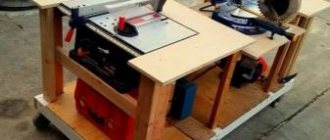
How to make a manual hoist - step by step diagram
: Tools
First you need to purchase everything you need. You will definitely need three support poles, the length of which is about 4 meters and a diameter of about 12 cm, a metal rod with a diameter of about 12 cm, and there should be a thread at the end, several washers and M12 nuts, as well as a metal chain.
: Installation of units
First you need to drill holes in each post-pole. A rod is pulled into these holes, where there are threads at the ends. Washers are put on the ends and nuts are screwed on; they limit the divergence of the racks on the rods. Next, you need to fix the chain on the sides on the middle pole on the rod, and this is done using holes. The chain should slack a little, and a block with a cable is installed on it, and it should run along the middle post and be secured at the bottom.
: Activation
We place the stands on the ground at an angle of 120 degrees, then lift them up by the connecting nodes, and install everything like tripods. Then you need to move each stand in turn to the central part of the device, so you need to set the required height of the hoist and the cone of the tripod. The load that needs to be lifted should be attached to a cable and, when rotating the gearbox, torn off from the surface. With such a device, you can easily lift lathes, and even change a tractor engine with its help. An important advantage of such hoists is that they can be installed and operated by one person. The height of the racks and the hoists themselves can be about 5 meters. Such tools are always easy to assemble and store in the garage. They are quickly disassembled and easily transported. To make them, you don’t need any special parts or elements; if you put in a little effort, the right device will appear in your home.
In farming and when performing certain construction work, there is often a need to lift or move heavy loads.
Invite a crane operator for every occasion - no amount of money will be enough. Therefore, after thinking about it, I made myself a manual mechanical hoist, which helped me a lot, which I will talk about below.
Having spread the stands on the ground at an angle of 120 degrees, we lift them up by the connecting node, installing them in the form of a tripod. By moving each stand on the ground one by one towards the center, we set the desired height of the hoist and the tripod cone. We hook the load intended for lifting to the cable and, by rotating the gearbox, lift it off the ground.
Using this device, I had to lift and load a 1B-61A lathe weighing more than a ton into a trailer at home and change the tractor engine. In addition, the hoist was often used on the farm to hang carcasses when skinning. And the device was very useful when installing the stone memorial sign “Orsici Village, 1560 years old.”
Important nuances
An additional advantage of the device is that installation and operation can be done by one person. The size of the racks can reach up to 5 m.
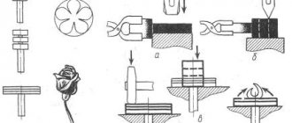
Rice. 1
Conventional drawing of the hoist 1 - support posts (3 pcs.), 2 - metal rod, 3 - nuts with washers (2 pcs.), 4 - chain Fig. 2
Kinematic diagram 1 - middle rack, 2 - block, 3 - cable, 4 - worm gear
How to hang a hoist in the garage
#1
The clay slabs lie on the walls, without beams. I don’t want to fence the beam, how can I properly make a hook in the ceiling under the hoist so that the whole structure doesn’t fall out?
Contract and new spare parts directly from factories for Japanese cars, delivery to the regions. Questions in PM.
Community of garage owners, www.garageforum.ru, our Instagram @garageforum.ru
- Top
#2
I have a rail thrown across the entire garage))) So attach it to it however you want)) + The roof in this place is a little higher than at the beginning)
- Top
Article on the topic: How to paint a caisson in a garage
#3
With a rail it’s clear, but I don’t have one, it’s dangerous to put it into a wall - one is load-bearing, the second is one brick like a partition between garages
Contract and new spare parts directly from factories for Japanese cars, delivery to the regions. Questions in PM.
Community of garage owners, www.garageforum.ru, our Instagram @garageforum.ru
- Top
#4
There is an opinion that you will have to break through the ceiling, make an X-shaped structure from the outside in the center of which there will be a mount for a winch hoist, otherwise it will definitely tear out
Contract and new spare parts directly from factories for Japanese cars, delivery to the regions. Questions in PM.
Community of garage owners, www.garageforum.ru, our Instagram @garageforum.ru
- Top
#5
There is an opinion on some forums
take the rail and cut it into 3 parts 2 parts - will be supports 3 - load-bearing across, hang the hoist on it
leaning on a concrete roof is fundamentally wrong, it is not designed for such loads
In my case, the correct option would probably be either as listed above, or to make an “elephant” or a folding (wall-mounted) crane beam
Contract and new spare parts directly from factories for Japanese cars, delivery to the regions. Questions in PM.
Community of garage owners, www.garageforum.ru, our Instagram @garageforum.ru
- Top
#6
Is this option suitable for a non-load-bearing wall?
A 160 I-beam 4 m long (beam) lies on 80 angles anchored into the wall, pressed on top with another smaller angle and secured by welding. Hoist with a single carriage with a load capacity of 0.5 tons, lifting height 2.5 m.
Contract and new spare parts directly from factories for Japanese cars, delivery to the regions. Questions in PM.
Community of garage owners, www.garageforum.ru, our Instagram @garageforum.ru
- Top
#7
Damn how unreliable it is, I wouldn’t hang it heavier than a sack of potatoes))) if initially the dvutar had been on the walls and not bolted on, then there would have been no need to be afraid))) otherwise it’s sticky)))
- Top
Article on the topic: Which tiles to choose for the garage
#8
Why are weaving anchors dangerous in this case? I don’t understand, but if the I-beam is inserted into the walls onto a brick (removed with a hammer drill), the same thing will happen, but in my case, the partition between the garages is not across, but along. According to this scheme, if I understood correctly, even if one side starts to tear, it will burst against the second wall. If I understand correctly, the risk is only of the anchor pin breaking
Contract and new spare parts directly from factories for Japanese cars, delivery to the regions. Questions in PM.
Community of garage owners, www.garageforum.ru, our Instagram @garageforum.ru
- Top
#9
Why are weaving anchors dangerous in this case? I don’t understand, but if the I-beam is inserted into the walls onto a brick (removed with a hammer drill), the same thing will happen, but in my case, the partition between the garages is not across, but along. According to this scheme, if I understood correctly, even if one side starts to tear, it will burst against the second wall. If I understand correctly, the risk is only of the anchor pin breaking
That’s just the point, it will break the anchor))) the I-beam itself weighs a lot))) drill holes into the neighbors and drive the I-beam through them))) so that you don’t get hit by the I-beam)))) And in general, it might be easier to take a goose for swaps, and don't worry))
Basically, all lifting equipment for car service centers is equipped with a chain mechanism. Therefore, it is important to buy a tool with strong and reliable links that will not burst under heavy load. To determine the quality of the chain, you should pay attention to:
- material of manufacture;
- thickness of links;
- strength of connection of links.
Also consider the environmental conditions in which the model can be used.
Lever hoist – advantageous physics of load capacity
This type of hoist is necessary for working with small loads, the weight of which is no more than 5 tons, and it can be raised to a height equal to the height of a person. It all depends on the design solution. Raising, lowering and moving is carried out using a lever built into the body. The hoist is controlled by an operator located near the device. Such models are good for tensioning cables and lifting loads. Since they are not suitable for a large volume of work, utility services find use for them.
They are necessary when you need to tension cables or install pipes at the bottom of trenches, as well as for installing hatches. With their help, foresters pull out stumps, and industrialists place heavy equipment in workshops. Often their purpose is to lift a load in order to work with it, like this. This can be various repair work, for example, in car repair shops. To make working with lever hoists easier, they are additionally equipped with special trolleys.
Hand winch
Manual winches include any devices that allow you to move loads and are manually driven. The most common are drum-type winches: a cable is wound on a reel, and the rotation of the reel is carried out using a handle through a gearbox: a worm or a system of sprockets of different sizes. The higher the gear ratio, the less force is required to apply to the handle.
For effective operation, the hand winch must be rigidly fixed to a stationary object; for this purpose, mounting holes are made on the winch frame. The handle is connected to a shaft on which a small sprocket is rigidly fixed. The coil is rigidly connected to a large sprocket, which has a clutch with a small one. The cable is attached at one end to the reel, and a carabiner or hook is attached to the other end.
How to make the base frame of a crane lifting mechanism
The main load falls on the equipment racks, so to securely fix the structure it is necessary to build a strong frame . The construction of an element involves the following actions:
- Legs for the faucet are made from metal corners using a welding machine and welded at an angle of 45 degrees on each side of a pipe with a diameter of 110 mm. Metal triangles are welded to the posts to create spacers.
- To ensure the movement of the structure to the horizontal base, rollers are welded on both sides of the racks. It is important to use casters designed for metal containers as they can support a lot of weight.
- A pipe is placed on top of the structure along which the lifting mechanism moves. The length of the pipe depends on the size of the garage and your own design requirements.
- The roller for moving the cable is fixed to an I-beam, which is pre-welded in the center of the pipe.
- For additional stability of the frame, a pipe with a square cross-section is welded to the beam. It is placed on top of the beam so that there is a 20 cm protrusion on each side.
- The cross pipe is inserted into a pipe with a square cross-section and through openings are made for the clamps on both sides. Mounting bolts are inserted into the holes and tightened.
Installation of lifting mechanism - manual or automatic
To mechanically lift loads onto the frame, you need to install a manual hoist - a worm winch and a cable. How to attach the hoist to the frame:
- on the side of the rack we install a manual worm winch (load capacity 800 kg, no less);
- The steel cable moves along rollers.
This mechanism makes it easy to lift the engine or car by the hood on one side.
You can use the lifting mechanism and rollers from the elevator door as a drive. The rollers there are reliable and durable.
An electric lift drive can also be installed on the manufactured base. A 300 - 500 W motor will be quite enough for simple repair work in the garage.
Such cranes are often used for the repair and reconstruction of old wooden houses. The construction of a log house will go faster if the logs are laid using a mobile homemade crane. In this case, the width of the frame is the length of the logs.
You can also make a simpler lift for the engine, on one support, watch the video.
Types of lifting devices
What the pulley for lifting loads and the construction crane have in common is the use of the idea of increasing force - the rule of leverage. In order to balance the load on the short side of the lever, you need to apply less force to its long side to the extent that the short arm is less than the long one. The ratio of forces at the ends of the lever is called the gear ratio.
You can balance and even lift a weight with an effort less than its weight, but the path made by the end of a long lever will be longer than that of a short one, just as less force was applied to lift it. There is no gain in work (F1*L1=F2*L2), but this is not required.
The use of Archimedes' principle is implemented in different lifting mechanisms, and how depends on the purpose of the lift. Designs differ in gear ratio, principle of force transfer, mobility, strength, and energy used. The most popular types for self-production:
- chain hoists;
- drum structures;
- lever mechanism.
To choose the type of device needed for specific work, it is worth familiarizing yourself with their capabilities and limitations.
Main characteristics
Main technical parameters of lifting equipment:
Jib crane - dimensions
- classification according to GOST 25546 - 2K, according to ISO 4301/1 - A2;
- execution – U, HL, UHL;
- placement according to standard 15150 – 1, 2, 3, 4;
- device rotation drive and control – manual;
- hoist control – manual, electric remote control;
- control position – from the floor;
- electrical wire – cable connection;
- load mass during testing – 1.25 for static testing, 1.1 for dynamic testing.
The last paragraph indicates a portion of the rated load capacity indicated in the passport.