and end surfaces
Fig 6 4 Processing
1. Which cutters are used for processing
external surfaces « 2 How different meanings of elements are determined
(angles) of cutters for the process of processing external
cylindrical surfaces" 3. What are the features of the application
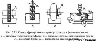
6.1. End cutting tools
Highlanders and ledges are processed with trimming, through, bent or through persistent cutters. The scoring end cutter (Fig. 6 1, i) is designed
Fig. 61 Trimming cutters and - dvv processing externally to the ends, b - dvv working with birth defects
and forever water
for processing external end surfaces. When cutting the end, the feed of the cutter is perpendicular to the axis of the workpiece. The scoring cutter (Fig. 6.1, b) allows
Rice. 62. Processing Fig 63. Processing
pass-through bent pass-through persistent
nenny prefabricated cutters and finishing of external surfaces"
4 Name the conditions for using various installation schemes for self-rotating cutters.
6. Explain the conditions for using cutters with plates made of oxide-carbide mineral ceramics, with inserts of CBN and polycrystalline diamonds.
process various ends and other surfaces with longitudinal and transverse feeds. Scoring cutters are made with plates made of high-speed steels and hard alloys. Main clearance angle o = 1О - ; 16′, rake angle T is selected depending on the material being processed.
Using a bent cutter (Fig. 6.2), you can trim the end with a transverse feed of 5" and grind with a longitudinal feed of 51 cutters. With a pass-through stop cutter (Fig. 6.3), you can trim the ends and grind the ledges with a longitudinal feed 5b Cutters for cutting the ends must be installed exactly along the axis of the part, otherwise a protrusion will remain at its end. With a large diameter of the end surface, the allowance is removed with a transverse feed of 5" in several working strokes. Ledges of more than 2 - 3 mm are trimmed with passing cutters in several steps. First, a ledge is formed with longitudinal feed 5b and then it is cut with transverse feed 5“ (Fig. 6.4).
When cutting the ends and ledges, the transverse and longitudinal feeds are determined in the same way as when turning cylindrical
lindrical surfaces. The transverse feed is usually less than the longitudinal feed. For roughing of ends, the cross feed is equal to 0.3 - 0.7 mm/rev at 1 = 2 - : mm, for finishing - 0.1 - 0 3 mm / rev at 1 = 0 7 -; 1 mm.
The cutting speed for this type of processing is usually 20 K higher than for processing cylindrical surfaces, since the time the cutter participates in the cutting process is insignificant and it does not have time to heat up to a critical temperature.
6.2. Grooving
and cutting of blanks
Narrow grooves are machined with slotted cutters. The shape of the cutting edge of the cutter corresponds to the shape of the groove being turned. Slotting cutters !Fig. 6.5, a - d) there are straight and bent, which in turn are divided into right and left. More often, slotted incisors are used: right straight and left bent. The rigidity of the part does not always allow cutting grooves of a given width in one working stroke of the cutter. If it is necessary to machine a wide groove (5 mm) in a non-rigid part, then perform several working strokes with transverse feed!Fig. 6.6). At the ends and along the diameter of the groove, an allowance of !0.5 - 1.0 mm is left for finishing. The final processing is performed with the same cutter or a groove cutter with a cutting edge equal to the specified groove size.
Workpieces and parts are cut with cutting tools!Fig. 6.7, a - d). The width of the cutting edge of the cutting tool depends on the diameter of the workpiece being cut and is taken to be 3, 4, 5, 6, 8 and 10 mm. Length
The head of the cutting cutter is made slightly larger than half the diameter D of the rod from which the workpiece is cut (b) 0.50).
Cutting cutters are made in one piece or with plates made of high-speed steel or carbide. To reduce friction between the cutter and the material being cut, the cutter head tapers towards the rod at an angle of 1 - 2′ (on each side of the cutter), angle l = O, clearance angle o = 12′. In parting cutters, the auxiliary entering angle should
Rice. 6.5. Slotted frolics: a - left-handed, b - right-handed, l-
ogoglugmy left, l - ogoglugmy prlvmy be less than the auxiliary rear angle. An incorrect ratio of these angles can lead to increased friction of the rear auxiliary surface of the cutter on the machined surface of the part.
Rice. 6.6. Consecutive !a, b, a) cutting a wide groove with a narrow cutter
Typically, the ends and shoulders are trimmed on lathes using scoring tools.
In Fig. 137, and a scoring cutter is shown.
It has a long cutting edge 1, usually installed at an angle of about 5° to the surface of the part being cut, and a short cutting edge 2. This edge is strongly beveled so that the tip of the cutter can be brought closer to the center of the part when cutting it in the centers (Fig. 137, b, c).
When cutting ends, shoulders and ledges that are not constrained by the center of the machine, use trimming thrust cutters shown in Fig. 138. These cutters can work with both longitudinal and transverse feeds. To trim ends or ledges in hard-to-reach places, for example, when you have to bring the cutter close to the chuck, bent scoring cutters are used (Fig. 139). For the same purposes, bent through cutters are often used (Fig. 140), which are given a transverse feed.
When cutting ends and shoulders, the tip of the cutter must be set exactly at the height of the centers. If the cutter is set below center, then there will be an uncut protrusion in the middle of the solid end. A cutter set above center may break.
Shoulders of small height can also be trimmed with a scoring stop cutter during longitudinal feed simultaneously with turning the cylindrical surface (Fig. 138). The correct location of the shoulder with this cutting method depends entirely on the installation of the cutter; its cutting edge must be strictly perpendicular to the axis of the part.
Large benches are usually processed in several passes, combining longitudinal feed with transverse feed. First, using a scoring cutter set at an angle of 5° to the surface of the ledge, a cylindrical section is processed, and a layer 2-3 mm deep is removed for each longitudinal pass. Then, using the same cutter, the ledge is finished trimmed with a feed directed from the center to the outer surface of the ledge.
Read also: Making a mold for steel casting
Techniques for cutting ends and ledges
When cutting the ends and ledges, the parts are installed using the same methods as for longitudinal turning.
Trimming the ends in the centers. When cutting the ends of parts installed in centers, it is recommended to install a so-called half-center
(see Fig. 137, b), ensuring trimming of the entire end. It is even better to use center holes with a safety (double) cone (Fig. 137, c). The feed direction in both cases is from the periphery to the center.
Trimming ends in a chuck. It is advisable to trim the ends of parts fixed in chucks not with a scoring cutter, but with a bent cutter through the cut (see Fig. 140). The latter has a more massive cutting part, allowing higher cutting conditions.
When cutting ends and high ledges, the feed direction can go from the outer surface to the center (Fig. 141, a) or from the center to the outer surface (Fig. 141, b). In the latter case, the force acting on the cutter tends to push its cutting edge away from the end of the part. Thanks to this, the end surface is cleaner than when working with a feed directed from the outer surface of the part to its center. However, this method of cutting ends and shoulders does not allow one to check the exact position of the end or shoulder after test cutting relative to other surfaces of the part. Therefore, the above rule about choosing the direction of transverse feed must sometimes be abandoned.
High performance work methods. When cutting a significant number of identical parts with ledges, a longitudinal feed should be used in connection with a stop that limits the movement of the caliper (see Fig. 131).
When it is necessary to maintain the lengths of individual steps regardless of the depth of the center holes, floating centers
(Fig. 142).
Such a center 1, mounted inside the housing 4, is inserted into the conical hole of the headstock spindle. Spring 5 tends to press the center to the right and create contact between the center and the part.
When the tailstock quill is pressed, the part installed in the centers is brought to a hardened stop 2 attached to the end of the body 4. After this, the floating center is locked with a bolt 3 while processing this part. When installing the next part, bolt 3 must be released.
The high-speed turner T. Kulagin, when cutting the end of a part with a hole (see Fig. 143), uses two cutters 1 and 2 simultaneously. These cutters are fixed with the same overhang in a special holder 3, which in turn is fixed in the tool holder 4. Cutter 2 cuts the end is from the outer diameter, and cutter 2, installed in the tool holder with the cutting edge down, is from the inner diameter. Thanks to simultaneous processing with two cutters, the processing length, and therefore the processing time, is reduced by 2 times. This method of cutting the end can be recommended for roughing, since when two cutters work simultaneously, it is difficult to obtain a smooth end without a shoulder.
Techniques for measuring ends and ledges. The straightness of the end surface can be checked using a ruler (Fig. 144), which is applied to the end surface. If there is a gap, you can determine its size by eye or with a special measuring plate—feeler gauge.
The correct location of the ledges along the length of the shaft is checked with a ruler (Fig. 145, a), a bore gauge (Fig. 145, b) or, more precisely, a depth gauge (Fig. 145, c). To accurately check a large number of identical parts, it is recommended to use templates (Fig. 146).
Cutting modes when trimming
When cutting ends and shoulders with a transverse feed, the depth of cut is the thickness of the layer being removed, and the feed is the amount of movement of the cutter in the transverse direction per revolution of the part.
When trimming, the following transverse feeds can be recommended: for roughing - from 0.3 to 0.7 mm/rev with a cutting depth of 2 to 5 mm; for finishing – from 0.1 to 3 mm/rev with a cutting depth of 0.7–1 mm.
When trimming ends, you can use the same cutting speed as when machining the outer cylindrical surface, but it should be calculated based on the larger diameter.
Defects when cutting ends and ledges and measures to prevent it
When cutting ends and ledges, the following types of defects are possible: 1) part of the surface of the end or ledge remains unprocessed; 2) incorrect location of the cut end or ledge along the length of the part; 3) non-perpendicular location of the ledge to the axis of the part; 4) insufficient cleanliness of the surface of the end or ledge.
1. The first type of defect occurs due to incorrect dimensions of the workpiece, small allowance for processing, incorrect installation and inaccurate alignment of the part in the chuck, incorrect installation of the cutter along the length of the part or along the height of the centers.
Such defects are usually irreparable, but they can be prevented by checking the dimensions of the workpiece, increasing the processing allowance, and checking that the part and cutter are installed correctly.
2. Incorrect location of the cut end or shoulder along the length occurs when the cutter is installed inaccurately or the self-propelled gun is turned off untimely (during longitudinal feed), as well as when the part is axially displaced in the chuck as a result of its insufficiently strong fastening. If at the same time the boundary of the ledge is crossed, then a defect of this type is irreparable. Such defects can be prevented by checking the installation of the cutters and the strength of fastening the part in the chuck, as well as by timely turning off the self-propelled gun when working with longitudinal feed.
3. A non-perpendicular arrangement of the end or shoulder to the axis of the part when working with transverse feed can result from inaccuracy of the support guides, as well as due to the spinning of the cutter due to its weak fastening in the tool holder, too small a cross-section of the cutter, or the carriage moving away if it is not locked. When working with longitudinal feed, a common cause is incorrect cutter installation. Marriage of this type can be prevented by eliminating the listed reasons.
4. Insufficient cleanliness of the surface of the end or shoulder is the result of excessive feed, large overhang of the cutter, insufficiently strong fastening of the cutter or part, improper sharpening of the cutter, significant dullness of the cutter, high viscosity of the metal being processed, trembling of the carriage or parts of the support, trembling or runout of the spindle or chuck .
Such marriage can be prevented by timely elimination of the causes that cause it.
Turning of various products on lathe equipment is carried out using a tool that is collectively called a turning cutter. Cutting tools are classified mainly according to their functional purpose, on which the design features of individual types, the design and configuration of their blades directly depend. Other classifying features relate to its orientation during the working process, the type of cutting part, as well as the material from which it is made. In addition to lathes for metalworking, there is similar equipment for turning wood products, the cutters of which have an excellent design and are only suitable for working with wood and plastics. To distinguish them from cutting tools for turning metals, the latter often uses the phrase “metal cutter” in its name. The standard sizes and design characteristics of turning tools are regulated by state and international standards and are indicated on their markings in the form of a special code.
Read also: Polymers used in everyday life
Structural elements of a turning tool
The main part of the turning cutting tool has approximately the same layout and configuration of the main parts. They mainly differ in the geometry of the cutting part, which is associated with the functional purpose of a particular type of cutting tool. In addition, there are several technologies for connecting the holder and the cutting part, on which the basic design of turning tools depends. Nevertheless, all models have approximately the same set of working planes and cutter head faces involved in the cutting process. In addition to the main ones that directly implement the process of removing the allowance, they also include elements responsible for the directional removal of the layer of removed metal, the formation and breaking of chips, etc. The figure below shows the classic elements of the cutter and their location on the cutting part.
One of the features of turning is that the horizontal longitudinal movement of the cutting tool can be carried out in two directions: from the spindle (to the right) and towards it (to the left). Changing the direction of movement requires changing the orientation of the cutting surfaces, so the tool industry produces turning tools in both versions. To determine whether it is a right or left incisor, you need to place your right palm on it with your fingers pointing towards the blade. If the thumb is to the right of the top, then it is right, and if not, it is left.
Cutting planes
The angular parameters of a cutting turning tool are calculated using a system of coordinate planes, among which the basic planes are the main plane, the cutting plane and the main secant plane. Their mutual inclination forms the sharpening angles of the cutting part, ensuring turning in design modes. In this way, the following angles are determined: the main front (γ), the main back (α), the point angle (β), as well as a number of other angles (see the right figure below).
Cutter angles
The operation of a turning tool during the cutting process is determined by the angular parameters of the front and rear surfaces. Therefore, the main angles of the incisor are the main anterior (γ) and the main rear (α). By increasing the first, power consumption for cutting is reduced, chip control is improved and roughness is reduced. On the other hand, as the rake angle increases, the thickness of the blade decreases, which leads to a deterioration in its strength characteristics, increased chipping and a decrease in the rate of heat dissipation. The main purpose of the clearance angle is to reduce friction between the cutting surface and the main clearance. In addition to the main functional angles α and γ, the calculation determines several more angles, whose values affect the class of turning cleanliness, the process of chip formation and other technical characteristics.
Types of cutters for a lathe and their purpose
When describing the types of turning tools, several classifying characteristics are usually used. According to its design, it is divided into two types: solid and prefabricated. In the first case, the entire product is made in the form of a monolithic bar of metal. And in the second, removable or soldered carbide plates act as the blade. According to their technological purpose, turning cutters are divided into special ones, which are used for processing various profiles and threading, and general purpose products, used for external and internal turning, cutting and end trimming. Another distinguishing feature of a turning tool is the configuration of the cutting part, which depends on its operating modes and the type of turning work. For turning hard-to-reach places, a curved cutter is usually used, which has several varieties, differing in the length of the cutting part, the shape of the bend, sharpening and purpose (cockerel, bent, reverse cutters and others).
Another classification option is the division of turning tools according to the principle of machining cleanliness. There are usually two classes here: rough and finishing. The first is intended for roughing or pre-turning operations, and the second is for finishing operations. If the rough tool, with rare exceptions, is quite the same type, then among the finishing tools there are a number of varieties with their own names. Examples include blade and radius cutters with an arcuate blade, the purpose of which is precise finishing turning. Another separate type is a diamond cutter, used for turning work on super-hard materials. A cup turning cutter with a circular cutting surface has a unique design that can work for a long time without regrinding.
In addition to the standard classification, there are many names for specific turning tools, usually reflecting the features of its design or technology of use. These include a spring cutter with a wave-shaped cutting part, which springs during turning of hard and uneven materials.
A separate category of cutting tools for lathes are planing cutters. During turning operations using them, feed is carried out on a stationary part. In this case, the allowance is not cut off, as during rotation, but is removed by planing. In this configuration, a lathe performs the same function as a planer or slotter.
Pass-through straight, bent and persistent
The most common turning operation is turning the outer parts of cylindrical workpieces. In this case, three basic types of cutting tools are used, shown in the figure below.
The thrust cutting tool is designed for turning long and non-rigid products, since its design contributes to less bending of the part. The bent cutter has a blade located at an angle to the holder, so it can be used for longitudinal feed. All cutters of this type are fixed in the tool holder so that their tip is opposite the main axis of rotation of the machine. One of the varieties of the straight type is a spring cutter, which has an elongated and curved cutting part that springs during processing. The through-cutting tool is the most widespread and universal, therefore it is often made non-separable from high-speed tool steel.
Scoring cutters
The main purpose of this tool is to trim ends and form ledges on rotating workpieces. Scoring cutters work in both feed directions and can therefore form shoulders at different angles. Structurally, these are most often prefabricated high-speed cutters. The photo below shows trimming the end of a bronze blank.
Read also: Homemade cars for children
Parting cutters
This type of turning tool belongs to the group of grooving and cutting tools. It is distinguished from pass-through and scoring cutters by the specific shape of the cutting part. On its blade, on the sides of the main working edge, there are two auxiliary grooves that ensure cutting of the side planes of the groove. In addition, to reduce friction on the side surfaces of the groove being cut, the cutting part has a trapezoidal shape with a narrowing towards the holder. The head of such a tool, as a rule, has a reinforced shape, often curved upward (the so-called cockerel incisor). It is recommended to cut off as close to the chuck as possible, with the cutting edge positioned exactly against the axis of rotation and the tool body strictly perpendicular to the cutting plane. Cutting work is performed at lower speeds than turning, and when cutting steel and hard metals, coolant must be supplied to the processing zone. The photo below shows a segment.
Threading internal and external cutters
If turning requires high precision in the relationship between the thread axis and other planes of the product, then in this case it is recommended to use thread-cutting tools. The technology of applying threads with a cutting tool is based on the exact correspondence of the geometric parameters of its cutting part and the threaded profile of the product. Regardless of the type of thread, during such operations the feed must be synchronized with the spindle speed. Structurally, the cutting tool used for external threads is straight, and for internal threads it is bent. The photo below shows external thread cutting.
Boring cutters
This type of tool is designed for turning internal cylindrical surfaces in order to achieve precise alignment with the axis of rotation of the part. When turning boring, chip removal, heat removal and the use of coolant are difficult, so the tool is in more difficult conditions than when performing external turning. As a result, such turning is performed at lower speeds and shallow depths. There are two main types of cutting boring tools: thrust and through. The former are intended for dead-end holes, and the latter for through holes. For boring large diameters, tool holders of various configurations are usually used, which can also accommodate boring cutters. The photo below shows a boring.
Prefabricated tool
Structurally, turning cutters are produced in two main varieties: all-metal and prefabricated. In the first case, the entire product is made of a single metal bar, at the end of which the blade is sharpened. In the second, everything is all-metal except the blade, which in such a product is a cutting plate fixed at the end of the tool head. The cutting inserts in this type of turning tool can be attached by soldering or mechanically. In the first case, it is fixed by soldering or welding, and in the second - by various mechanical devices, among which the most common are threaded elements, clamps and eccentrics. Tips and inserts for cutters are made from special cutting materials, the main ones being tool steel, hard alloys and powder composite materials.
Trimming ends and ledges
Trimming the ends and ledges is carried out using various methods of securing the part. The scheme of work depends on the specified processing accuracy, the size and location of surfaces, the shape of the cutter, etc. Trimming is carried out by scoring and through-thrust cutters.
When cutting the ends and ledges, it is necessary to maintain their flatness (only a slight concavity is allowed), perpendicularity to the axis of the part, correct location along the length, and roughness in accordance with the requirements of the working drawing. These conditions are ensured by proper installation and alignment of workpieces on the machine, and the use of appropriate cutters and work techniques.
Turning of ends in most cases is performed with the installation of workpieces in a chuck. If necessary, the workpieces are checked for the absence of runout. Long workpieces that do not fit into the spindle hole in diameter are installed in the chuck and the rear center or centers. In this case, to trim the end to the center hole (see Fig. 41, d), a thrust semi-center is installed in the tailstock quill.
To reduce the time for test grooves and measurements when processing parts in batches, it is advisable to give the workpieces a constant longitudinal position on the machine using spindle stops, shoulders of the chuck jaws, driving-floating centers, etc. For workpieces passed into the spindle hole, you can use an adjustable stop 3 (Fig. 40). It is installed on the rear threaded end of the spindle using a special nut 2, adjusted in length and secured with screw 1.
Installation of workpieces on the machine when cutting ledges is carried out in the same ways as when turning cylindrical surfaces.
trim the ends with bent cutters (Fig. 41, a), which have a massive head and, therefore, higher durability.
Small-diameter ends are trimmed with persistent cutters (Fig. 41, b), the main cutting edge of which is positioned to the surface being processed at an angle of 5-10°. The same ones. At the end of turning a cylindrical section, high ledges are cut with cutters using a transverse feed (Fig. 41, e).
For the actual trimming work, trimming cutters are provided, which, in addition to processing the ends (Fig. 41, c), can be used to trim a high ledge (Fig. 41, c) in several transverse passes and then, with a longitudinal movement, finally grind the cylindrical section.
The cutters are installed in the caliper tool holder with the smallest overhang, strictly at the level of the center axis and firmly secured.
The ends and high ledges are usually trimmed using a transverse feed of the cutter. Their location along the length is obtained by setting the cutter to the required size along the longitudinal feed dial or by marking using a ruler.
In all cases, when the main cutting edge of the cutter is located at an angle to the machined end, an axial force arises that tends to push the cutter to the side. When cutting with a large cutting depth, this force becomes significant, capable of moving the caliper longitudinally if the work is carried out with manual feed. As a result, the treated surface will be non-flat with increased roughness. In this case, the support should be kept from shifting by the longitudinal feed handwheel or secured with a clamping screw on the frame.
The position of the ends and ledges along the length of the part is measured with a ruler or caliper, which should be positioned strictly parallel to the axis of the part to avoid errors. The perpendicularity of the end to the axis of the cylindrical surface is checked with a square, flatness is checked by applying a ruler or square to the end of the edge, and roughness is checked by comparison with roughness standards.
Turning of ends and shoulders , due to various reasons, can lead to the following types of defects.
- Part of the surface remained untreated. Reasons: allowance is small; When installing the workpiece in the chuck, there was a misalignment; non-perpendicularity of the end of the workpiece to its axis.
- Inaccurate location of the end or shoulder along the length of the part. Reasons: measurement inaccuracy; no backlash is selected when using the dial.
- Non-perpendicularity of the end (ledge) to the axis of the part. Reason: when installing the workpiece in the chuck, there was a misalignment.
- Non-flatness of the machined surface. Reasons: large depth of cut and feed; non-rigid attachment of the cutter; longitudinal release of the caliper; excessive clearances in the caliper guides.
- Increased roughness.
Defects can be eliminated by careful attention to work, timely elimination of machine malfunctions, and the use of correct work techniques.
Main rules when choosing a turning tool for metal
When choosing a turning tool, first of all, you need to clearly understand for what purposes it is intended to be used and in what modes it will be used. In addition, an important criterion is the production purpose, on which its cost depends. The tool used for one-time turning work in a repair shop and the one used in mass production have different performance characteristics and, accordingly, have different prices.
However, all other things being equal, the key parameter is still the durability of the cutter, which depends on the material of its blade. Lathe cutters with replaceable inserts in many cases have the best characteristics, but when the blade fails, it is not sharpened, but must be replaced. An all-metal tool is more practical in this regard, since wear of the cutter only leads to its regrinding. In addition, the shape of the cutting edge of such a product can be set as desired.
When is sharpening required?
The need to sharpen cutters for a lathe arises in two situations: during the manufacture of a new tool and in case of wear during operation. It is impossible to work with a worn or incorrectly sharpened cutting tool, as this leads to a sharp loss of turning accuracy and a decrease in the surface quality of the part. Other consequences of sharpening problems include vibration and excessive heat.
Rules for sharpening
The purpose of sharpening turning tools is to bring their surfaces to the specified geometric characteristics and to give proper sharpness to the cutting edges. To properly sharpen a turning tool, it is necessary to follow the sharpening technology and use abrasive wheels that match the material of the product. It is also important that the sharpening machine is equipped with an adjustable tool rest, which allows you to fix the tool being sharpened at the required angles. The procedure for sharpening a turning cutter is as follows: the corners of both rear surfaces are removed first, and after checking and measuring them, the front surface is sharpened. The last operation is to fine-tune sections of all surfaces in those places where they are adjacent to the cutting edge of the blade.
Tools used
On the machine for sharpening turning tools, two grinding wheels with different abrasives should be installed: from electrocorundum and green silicon carbide. The first is intended for sharpening work on tool steel, and the second wheel is used for sharpening carbide materials. Lapping and finishing, which is the finishing operation, is carried out on a separate sharpening and grinding machine with minimal runout and high speeds. Here, CBN or diamond grinding wheels are used as abrasive tools.
4.1. GENERAL PROVISIONS
Screw-cutting lathes are used for cutting ends, centering, turning external cylindrical surfaces (including eccentric ones), processing through and blind cylindrical holes, turning conical and shaped surfaces, threading and other work. Trimming the ends . Usually, before turning the outer surfaces of the workpiece, one or both of its ends are trimmed. The ends are trimmed with continuous persistent, bent or scoring cutters with transverse feed to the center (Fig. 4.1, d) or from the center of the workpiece. The workpiece is usually secured in a chuck or on a faceplate. When trimming with a feed from the periphery to the center, the end of the workpiece turns out to be concave due to the action of the cutting force components Px and Ru on the cutter. When cutting from the center to the periphery, the end surface becomes less rough and the end is convex. During a repeated pass, the end of the workpiece is flat. When cutting shoulders and ledges with a continuous thrust cutter, they work with both longitudinal and transverse feed. When cutting the right end of the workpiece, use the cut center. Centering is used to obtain center sockets in long workpieces. Alignment must be performed very carefully, since the centering sockets are the basis for subsequent processing of workpieces, and are also used when editing and checking manufactured parts. During repair work, the remaining centering holes are used as bases for processing worn or damaged surfaces of parts. Centering is done using a drill and a countersink or using a combined centering drill. Grinding of external cylindrical surfaces is carried out with straight, bent or persistent cutters with longitudinal feed (Fig. 4.1, a) when securing the workpieces in the chuck, on the faceplate, in the chuck and the center, in the centers, on the mandrel and special devices. Short parts with L/D < 4 (where L is the length of the workpiece, D is its diameter) are fixed in the chuck, parts with 4 < L/D < 10 - in the centers or in the chuck, supported by the center of the tailstock. When L/D > 10, the workpieces are mounted in centers (or in a chuck, supported by the center of the tailstock) and are also supported by a steady rest.
Rice. 4.1. Schemes for processing workpieces on a screw-cutting lathe: a – turning of external cylindrical surfaces; b, c, – turning of stepped shafts; d – cutting the ends; d – turning fillets and roundings; e – turning grooves; g – drilling holes; h, i – boring of holes; k, l – cutting off processed workpieces
When working on centers, to reduce friction and heat, it is necessary to fill the center holes with a thick lubricant (65% grease, 25% chalk, 5% sulfur and 5% graphite). It is advisable to process parts such as bushings, gears, etc., with machined holes, on a mandrel to obtain concentricity of the outer and internal surfaces, as well as to ensure that the end surface is perpendicular to the axis of the part. Mandrel turning is usually used for finishing. Smooth shafts are processed by installing the workpiece on the centers. First, one end of the workpiece is turned to the length necessary to install and secure the clamp, and then it is turned 180° and the rest of the part is turned. Stepped shafts are turned according to two schemes: dividing the allowance into parts (Fig. 4.1, b) or dividing the length of the workpiece into parts (Fig. 4.1, c). In the first case, workpieces are processed with smaller cutting depths, but the overall path of the cutter is large and the main (technological) machine time (To) increases sharply. In the second case, the allowance from each stage is cut off immediately due to the processing of the workpiece with a large cutting depth. In this case, To decreases, but greater machine drive power is required. It is recommended to process non-rigid shafts with through-thrust cutters with a main entering angle j = 90°. When processing shaft workpieces with such cutters, the radial component of the cutting force is Pу = 0, which reduces the deformation of the workpieces. Turning fillets and roundings (Fig. 4.1, d). This operation is performed using passing cutters with a rounding between the cutting edges along the appropriate radius with longitudinal feed or special fillet cutters with transverse feed. Grooving (Fig. 4.1, e) is carried out with a transverse feed by slotted cutters, in which the length of the main cutting edge is equal to the width of the groove being machined. Wide grooves are machined with the same cutters, first with a transverse and then with a longitudinal feed. Drilling, countersinking, countersinking and reaming of holes are performed with appropriate tools mounted in the tailstock quill. (Fig. 4.1, g) shows a diagram of drilling a cylindrical hole in a workpiece. Boring of internal cylindrical surfaces is carried out using boring cutters fixed in the tool holder of the machine, with longitudinal feed. Smooth through holes are bored with continuous boring cutters (Fig. 4.1, h); stepped and blind cylindrical holes - with persistent boring cutters (Fig. 4.1, i). Usually, after boring a blind or stepped hole to a given length, turn off the longitudinal feed, turn on the transverse feed, and trim the inner end (bottom) of the hole. Cutting of processed parts is carried out using cutting tools with transverse feed. The cutter has a long narrow head, to save metal - along the width of the cut. However, as the width of the cutting part decreases, the rigidity and strength of the cutter decreases. For workpieces with a diameter of 30–50 mm, the width of the cutting part of the cutter is 3–5 mm. For better chip removal, a hole is sharpened on the front surface of the cutter, and to reduce friction on the sides, auxiliary angles j1 within 1–2° are used. When cutting a part with a cutter with a straight cutting blade (Fig. 4.1, j), the resulting neck is destroyed, and the end of the finished part has to be additionally trimmed. When cutting a part with a cutter with an inclined cutting blade (Fig. 4.1, l), the end is clean and no additional trimming is required. When processing workpieces using semi-automatic and automatic machines, the processed parts are cut off from the rod using cutting tools with an inclined cutting blade. Turning of shaped surfaces of workpieces with a generatrix length of up to 40 mm is carried out using turning shaped cutters. They are divided into rod, round, prismatic and tangential. Long shaped surfaces are processed with pass-through cutters with longitudinal feed using a shaped copier installed instead of a copying cone ruler.
How to install a cutter on a machine
The turning tool is mounted on the carriage of the movable support using a single or multi-position tool holder. To correctly install the cutter, it must be accurately aligned relative to the main axis of the machine in the perpendicular and parallel directions. The cutting edge of most turning tools must be strictly opposite the axis of rotation, which requires the tool to be adjusted in height. To do this, they usually use mild steel plates of different thicknesses, which are placed under its base. An important installation condition is also the rigid fixation of the cutter, so it must be clamped without backlash or gaps.
If any of the readers have experience working on a lathe, please tell me how many turning tools and what type should be available in a home workshop. We look forward to your response in the comments to this article.
Trimming as one of the operations on a lathe
Scoring cutters play a big role in the operation of trimming the end and ledge parts, which is carried out on turning equipment.
The scoring cutter is equipped with a long or short edge. The long edge is located at an angle of five degrees relative to the workpiece, the short edge is necessary for processing its central part.
Cutters come in different types and are used to process different parts. For example, for processing sides, ends and ledges, trimming thrust cutters are actively used, which are equally good for longitudinal or transverse cutting. The scoring and bent cutter is used for working with hard-to-reach parts of the part.
During the cutting procedure, the cutter must be positioned taking into account the height of the centers, otherwise the part will be processed poorly and the cutter may break.
The scoring stop cutter is used for processing parts of small height. It is installed perpendicular to the axis of the part and, using longitudinal feed and turning, performs processing.
Shoulders with a large height are processed with both longitudinal and transverse feeds sequentially. Using a scoring cutter, it is directed at an angle of five degrees and a layer of metal of no more than 2-3 millimeters is removed. After such processing, finishing is carried out, where the cutter is directed not to the center, but from the center to the ledge.
Each type of part has its own processing secrets. For example, the ends in the centers are trimmed with a half-center, which trims the entire end. The cutter is directed from the peripheral part to the central part.
The ends in the chuck are trimmed with a bent cutter, which has a larger cutting part, ensuring high processing speed.
High ledges and ends are cut towards the central part or, conversely, away from the central part. If you cut from the central part, then the end has a cleaner surface. But using this method it is impossible to control the accuracy of the location of the end or ledge in relation to the other surfaces of the part. Therefore, more productive methods of processing parts are used, which include connection with some additional method.
If it is necessary to process similar parts in a large volume, a stop and longitudinal feed are used. The support limits the feed of the caliper.
Using floating centers, the length of individual steps is maintained regardless of the depth of the holes.
You can use several cutters in your work. This will only speed up the processing of parts. However, the quality of work decreases, i.e. the end is not so smooth and perfect.
The accuracy of the cut is checked using rulers and other measuring instruments, as well as templates.
In order to ensure high-quality work, there are several transmission speeds. For roughing, a speed of 0.3 or 0.7 revolutions is used, and the cutting depth should be 2 or 5 millimeters. For finishing, a speed of 0.1 or 3 revolutions is used, with a cutting depth of 0.7 to 1 millimeter.
If the ends are trimmed, then it is permissible to use these speed parameters, but they need to be calculated for a large diameter.
During trimming work, defects are possible. It comes in four types:
1. The end surface is not completely processed;
2. The end or ledge is positioned incorrectly in relation to the length of the part;
3. The shoulder in relation to the axis of the part has a non-perpendicular value;
4. The ledge or end has insufficient surface cleanliness.
The first defect cannot be corrected, so it is best to prevent it during work by checking the dimensions of the workpiece, increasing the allowance and checking whether the part and the cutter are installed correctly.
The second defect can be corrected only if there is no crossing of the ledge boundary. Therefore, it is best to prevent it at the very beginning by checking the fixation of the cutters, parts, and timely shutdown of the self-propelled gun.
The third type of defect is associated with incorrect installation of the cutter, which also needs to be prevented at the beginning of work.
The fourth type of defect is also prevented with the help of optimal feed, strong fastening of the cutter and the part, preventing the cutter from becoming dull, and tightening the nodal connections.
Turning equipment ensures long-term and high-quality operation of your enterprise without forced stops and downtime.