2.5.1 General information
A keyed connection is a detachable connection that forms a shaft, a key and a hub (gear, pulley, sprocket, etc.). The key is a connecting part installed in the grooves of the shaft and hub. It serves to transmit torque between the shaft and the hub. The main types of keys are standardized. Keyways on shafts are obtained by milling with disk or end mills, and in hubs - by broaches.
2.5.2 Advantages and disadvantages of keyed connections
The advantages of keyed connections are simplicity of design and relative ease of installation and dismantling, which is why they are used in almost all branches of mechanical engineering.
The disadvantages of keyed connections are severe weakening of the shaft and hub. The weakening is due not only to the reduction in its cross-section, but also to the significant stress concentration caused by the keyway, which leads to a decrease in the fatigue strength of the shaft.
The main condition for the normal operation of keys is the absence of misalignment of the key in the groove. This can be achieved if the gap between the key and the groove is minimal, which requires increased precision in the manufacture of the key and groove or manual adjustment or selection of the key. This limits the use of compounds in large-scale and mass production. In the presence of misalignment, the contact area of the working surface of the key and the groove is significantly reduced, and, consequently, the load capacity of the connection drops sharply.
Due to the voids in the gaps between the key and the grooves, there is a slight displacement of the centers of mass relative to the geometric center, which leads to runout, especially noticeable at high rotation speeds. Therefore, the use of a keyed connection for high-speed rotating shafts for critical purposes is not recommended.
2.5.3 Types of keyed connections
Keyed connections are divided into stressed
and
relaxed
.
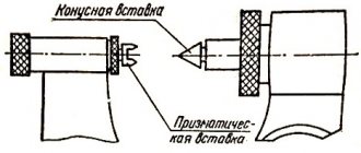
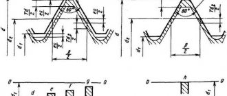
Wedge keys
(Fig. 2.40) have a slope of the upper edge of 1:100.
Such a key is installed in the groove and hammered into place, ensuring a tense connection. The wedge key expands the connection, causing a pressing force N
(Fig. 2.40
c
), which ensures joint rotation of the shaft and hub due to friction forces. The working faces are the top and bottom faces of the taper key.
The main disadvantages of wedge keys: mandatory individual adjustment, which is unacceptable in mass production; the presence of a radial displacement of the axis of the mounted part relative to the shaft axis, which causes additional runout. Therefore, they are used relatively rarely - mainly in low-speed low-precision transmissions and only for fixed connections.
Hello! We continue the series of articles about dowels on the SoproMats website. In this article we will tell you in detail what types of dowels exist.
There are several types of dowels , these are:
- prismatic is produced according to state standard 23360-78;
- segmental - according to GOST 24071-97;
- cylindrical (pin) - according to GOST 3128-70, 12207-79;
- wedge - according to state standard 24068-80;
- tangential wedge - according to GOST 24069-97, 24070-80.
Keyed connections
Characteristics of keyed connections
A keyed connection is formed by a shaft, a key and a wheel hub (pulley, sprocket, etc.). The key is a steel bar installed in the grooves of the shaft and hub. It serves to transmit torque from the shaft to the hub and vice versa. The main types of keys are standardized.
Keyways on shafts are obtained by milling with disk or end mills, in hubs - by broaching (see Fig. 1).
The advantages of keyed connections are their simplicity of design, as a result of which they are widely used in all areas of mechanical engineering.
Disadvantages - keyways weaken the shaft and hub of the part mounted on the shaft. The weakening of the shaft is due not only to a decrease in its cross-section, but, most importantly, to a significant concentration of bending and torsion stresses caused by the keyway.
A keyed connection is labor-intensive to manufacture: when making a groove with an end mill, manual adjustment of the key to the groove is required; when manufactured with a disk cutter, the key is secured in the groove with screws to prevent possible axial movements.
Classification of keyed connections
Keyed connections are divided into non-stressed and stressed. Stress-free connections are obtained using prismatic and segmental keys. When assembling these connections, no assembly stresses occur in the parts. To ensure centering and eliminate contact corrosion (fretting corrosion), the hubs are installed on the shafts with interference.
Tense connections are obtained using wedge and tangential keys (Fig. 2). When assembling such connections, preliminary (installation) stresses arise. Tangential keys are a type of wedge key. When pressing the wedge keys into the joint, radial expansion forces arise, which leads to an imbalance. Wedge keys are rarely used nowadays, so their strength calculation method is not considered here.
Read also: How to measure resistance with a multimeter video
Based on their shape, there are three main types of keys (except for wedge and tangential keys, Fig. 2) - prismatic, segmental and round.
Parallel keys (Fig. 3) are manufactured in several designs - with flat and rounded ends. Rounding the ends of the key facilitates installation of the structure. Keys with flat ends are installed near parts (end washers, rings, etc.) that prevent its axial movement, since the parallel key does not prevent the axial movement of parts along the shaft. Sometimes, to secure against axial displacement, parallel keys are fixed with spacer bushings or set screws.
Segmental keys (Fig. 3), like prismatic keys, work only with their side faces. They are used when transmitting relatively small torques, since a deep groove significantly weakens the shaft. Segmental keys and grooves for them are easy to manufacture and convenient for installation and dismantling. The deep seating of the key ensures its stable position. Unlike parallel keys, segmental keys do not require additional fixation against axial movement.
Key material and permissible stresses
Standard keys are made from a special range of medium-carbon clean-drawn steel with σв≥ 600 MPa - most often from steel grades St6, 45, 50.
The permissible bearing stresses [σ]cm for keyed connections depend on the material of the hub (the shaft is usually made of steel), the type of hub fit and the nature of the load.
Thus, a fixed connection with a steel hub allows a stress of 140...200 MPa, with a cast iron hub - 80...110 MPa. Higher voltages are allowed with a constant load, smaller ones with a variable load.
Allowable stress when cutting keys [τ]av = 70…100 MPa (N/mm2). Higher permissible voltages are accepted for constant load.
Calculation of keyed connections
The main criterion for the performance of keyed connections is strength. Keys are selected according to GOST tables depending on the diameter of the shaft, and then the connections are checked by calculation for strength. The nature of the stresses arising in the keyed connection during operation is shown in Fig. 4 . The keys work against crushing and shearing, and the side walls of the grooves on the shafts and in the hubs work against crushing.
The dimensions of the keys and grooves are selected so that their shear and bending strength is ensured if the crushing strength condition is met, therefore the main calculation of key joints is the calculation for key crushing. In most cases, keys are not checked for shearing.
When calculating, it is conventionally assumed that the compression stress σcm is distributed evenly over the contact area of the side faces of the keys and keyways, and the strength of the material, the nature of the connection, and the operating mode are taken into account when choosing the permissible stress [σ]cm.
A check calculation of a parallel key connection is performed according to the crushing strength condition (see Fig. 4):
where: F1 is the circumferential force transmitted by the key, Acm is the crushing area of the key (mm 2).
where: T = transmitted torque (Nm); d – shaft diameter (mm).
The part of the key protruding from the shaft, which has a smaller crushing area, is calculated for crushing. When determining the crushing area Acm, the chamfer size f is taken into account, which for standard keys is approximately equal to 0.06h (here h is the total height of the key).
A key with a chamfer f = 0.06h has a calculated bearing area Acm:
where: t1 – depth of the keyway on the shaft (mm); lр – design length of the key (mm). For keys with flat ends lp = l, with rounded ends lp = l – b.
Read also: Do-it-yourself thyristor DC power regulator
Substituting the values of F1 and Acm into the verification calculation formula, we obtain:
In the design calculation of the connection, after selecting the dimensions b and h of the cross-section of the key according to the standard, the design working length lp is determined:
The length of the hub lst is taken to be 8…10 mm longer than the length of the key. If the length of the hub is greater than 1.5d, then it is advisable to replace the keyed connection with a spline or interference connection in order to avoid significant uneven stress distribution along the length of the key.
A verification calculation of the connection with a segment key is performed for compression:
where: lp ≈ l – working length of the key (mm); (h – t) – working depth of the groove in the hub (mm).
Since segment keys are made narrow, they, unlike prismatic keys, are checked for shearing. Shear strength condition:
where: b – key width (mm); [τ]сp – permissible shear stress.
Recommendations for the design of keyed connections
When designing and constructing keyed connections, the following recommendations should be adhered to, based on operating experience and analytical findings:
- The difference in the diameters of the shaft steps with feather keys is determined based on the condition of free passage of a part with a larger landing diameter without removing the key from the groove in the area of the smaller diameter.
- If there are several keyways on the shaft, they are placed on one generatrix.
- For ease of manufacture, it is recommended to assign keys of the same cross-section to different stages of the same shaft, based on the stage with a smaller diameter. In this case, the strength of the keyed connections turns out to be quite sufficient, since the circumferential forces in different sections of the shaft are inversely proportional to the diameter, therefore, in sections with a large diameter, the circumferential force will be less.
- If it is necessary to install two segment keys, they are placed along the shaft in one groove of the hub. Placing several keys in one connection greatly weakens the shaft, so it is recommended in this case to switch to a splined connection.
Example of design calculation of a key
Task Select the type of standard key connection between a steel gear and a steel shaft and select the dimensions of the key. Shaft diameter d = 45 mm. The connection transmits a torque T = 210 Nm at a quiet load.
Solution We carry out a design calculation, on the basis of which we select the required key.
Connection selection:
To connect the shaft to the wheel, we use a widely used parallel key with rounded ends (version I).
Calculated dimensions of the key and groove on the shaft:
According to the standard table, which establishes the relationship between the shaft diameter, the size of the key section and the depth of the groove, we accept for d = 45 mm:
b = 14 mm; h = 9 mm, groove depth on the shaft t1 = 5.5 mm.
Allowable voltages:
According to the standard table, which establishes the dependence of the permissible stress on the type of key connection and the material of the hub, we accept for a steel hub, a fixed connection and a quiet load:
Application
The main application of keyed connections is mounting on a shaft using a grooved connection. In most cases, the keyway resembles a wedge. This type of connection of parts allows the shaft and hub not to rotate relative to each other’s axis. The fixed position of the hub to the shaft with a key allows for high efficiency when transmitting force.
Most often, keyed connections can be found in mechanical engineering, during the construction of machine tools. It is often used in the production of cars and other mechanisms, where increased reliability of fixing machine parts is required. High reliability is achieved thanks to the function of the shaft safety unit with keyway.
The key acts as a fuse in cases where the maximum torque level is exceeded. In such cases, the key is sheared, absorbing the excessive load and removing it from the shaft and hub.
Due to its properties, it has become widespread in mechanical engineering; it is characterized by high efficiency, ease of manufacture and installation, and low cost. Such characteristics are especially important in industrial production, especially in agriculture. At the height of the season, there are often cases of breakdowns of individual components that need to be replaced as quickly as possible. Most often found in baler units.
Considering all of the above, the main positions for which a key is needed are highlighted:
- Ensuring the safety of connected nodes under increased loads.
- Achieving a high degree of fixation of individual elements of a mechanical assembly.
- Performs the function of preventing rotation of the unit and hub.
- The reliability of such a connection exceeds the reliability of analogues when fixing the shaft with parts.
In general, you can find a keyed connection in almost any complex mechanism, which is due to its technical characteristics.
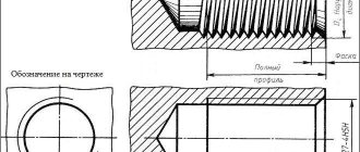
Designations on the drawings
In the drawings, the designation of parallel keys is based on the GOST regulatory document. They are divided into keyways: high, normal height and guides. Their working faces are the lateral ones.
In the assembly drawing, the designation is made taking into account the shaft diameter, torque, cross-section and length.
For example:
Key 3–20Х12Х120 GOST 23360-78; Where 3 is the design, 20X12 is the section, 120 is the length.
Download GOST 23360-78
The designation of other types of keys in the images is carried out in the same way, based on the corresponding GOSTs developed for each individual model. The specified designation must clearly characterize the part, which is very important for obtaining a reliable connection. After all, even the slightest gap can cause rapid wear of working units and loss of efficiency during operation.
APPENDIX 3 Recommended
DEPENDENCE OF SURFACE ROUGHNESS PARAMETERS ON SIZE TOLERANCE
| Size tolerance according to quality | Nominal sizes | |||
| Before 18 | St. 18 to 50 | St. 50 to 120 | St. 120 to 500 | |
| IT9 | 3,2 | 3,2 | 6,3 | 6,3 |
| IT10 | 3,2 | 6,3 | 6,3 | 6,3 |
| IT11 | 6,3 | 6,3 | 12,5 | 12,5 |
| IT12, 13 | 12,5 | 12,5 | 25 | 25 |
| IT14, 15 | 12,5 | 25 | 50 | 50 |
APPENDIX 3. (Introduced additionally, Amendment No. 1).
APPENDIX 1 Reference
Dimensions in mm
| 10 | 12 | 14 | 16 | 18 | 20 | 22 | 25 | 28 | 32 | 36 | 40 | 45 | 50 | 56 | 63 | 70 | 80 | 90 | 100 | |
| 9 | 11 | 12 | 14 | 16 | 18 | 20 | 22 | 25 | 28 | 32 | 36 | 40 | 45 | 50 | 60 | 65 | 75 | 85 | 90 | |
| Theoretical weight of one key of version 2, kg | ||||||||||||||||||||
| 22 | 0,015 | |||||||||||||||||||
| 25 | 0,018 | |||||||||||||||||||
| 28 | 0,019 | 0,029 | ||||||||||||||||||
| 32 | 0,023 | 0,033 | ||||||||||||||||||
| 36 | 0,025 | 0,037 | 0,047 | |||||||||||||||||
| 40 | 0,028 | 0,041 | 0,052 | |||||||||||||||||
| 45 | 0,032 | 0,046 | 0,059 | 0,079 | ||||||||||||||||
| 50 | 0,035 | 0,052 | 0,066 | 0,087 | 0,112 | |||||||||||||||
| 56 | 0,039 | 0,058 | 0,073 | 0,098 | 0,126 | 0,157 | ||||||||||||||
| 63 | 0,044 | 0,065 | 0,083 | 0,110 | 0,142 | 0,176 | 0,216 | |||||||||||||
| 70 | 0,049 | 0,072 | 0,092 | 0,122 | 0,157 | 0,197 | 0,240 | 0,300 | ||||||||||||
| 80 | 0,056 | 0,082 | 0,105 | 0,139 | 0,179 | 0,225 | 0,275 | 0,343 | 0,437 | |||||||||||
| 90 | 0,063 | 0,093 | 0,118 | 0,157 | 0,202 | 0,253 | 0,309 | 0,386 | 0,491 | 0,629 | ||||||||||
| 100 | 0,070 | 0,103 | 0,131 | 0,175 | 0,225 | 0,281 | 0,343 | 0,429 | 0,546 | 0,699 | 0,897 | 1,123 | ||||||||
| 110 | 0,077 | 0,113 | 0,144 | 0,192 | 0,247 | 0,309 | 0,378 | 0,472 | 0,601 | 0,768 | 0,989 | 1,236 | 1,544 | |||||||
| 125 | 0,129 | 0,164 | 0,217 | 0,281 | 0,341 | 0,429 | 0,536 | 0,683 | 0,874 | 1,123 | 1,404 | 1,755 | 2,069 | |||||||
| 140 | 0,142 | 0,183 | 0,244 | 0,314 | 0,393 | 0,480 | 0,600 | 0,764 | 0,978 | 1,258 | 1,573 | 1,966 | 2,317 | 3,048 | ||||||
| 160 | 0,210 | 0,279 | 0,359 | 0,449 | 0,549 | 0,686 | 0,873 | 1,118 | 1,437 | 1,797 | 2,246 | 2,648 | 3,494 | 4,707 | ||||||
| 180 | 0,314 | 0,403 | 0,503 | 0,608 | 0,772 | 0,982 | 1,258 | 1,617 | 2,022 | 2,527 | 2,979 | 3,931 | 5,277 | 6,368 | ||||||
| 200 | 0,449 | 0,562 | 0,686 | 0,858 | 1,092 | 1,398 | 1,797 | 2,246 | 2,808 | 3,310 | 4,368 | 5,896 | 7,098 | 9,360 | ||||||
| 220 | 0,618 | 0,755 | 0,944 | 1,201 | 1,537 | 1,976 | 2,476 | 3,089 | 3,641 | 4,805 | 6,486 | 7,798 | 10,296 | 13,117 | ||||||
| 250 | 0,858 | 1,072 | 1,365 | 1,747 | 2,246 | 2,808 | 3,510 | 4,137 | 5,460 | 7,361 | 8,872 | 11,700 | 14,897 | 18,525 | ||||||
| 280 | 1,201 | 1,529 | 1,957 | 2,515 | 3,145 | 3,931 | 4,634 | 6,115 | 8,255 | 9,937 | 13,104 | 16,698 | 20,748 | |||||||
| 320 | 1,747 | 2,236 | 2,875 | 3,594 | 4,493 | 5,296 | 6,988 | 9,435 | 11,337 | 14,976 | 19,094 | 23,712 | ||||||||
| 360 | 2,516 | 3,235 | 4,044 | 5,054 | 5,958 | 7,852 | 10,614 | 12,776 | 16,848 | 21,481 | 26,676 | |||||||||
| 400 | 3,593 | 4,492 | 5,616 | 6,620 | 8,736 | 11,793 | 14,196 | 18,720 | 23,858 | 29,640 | ||||||||||
| 450 | 6,318 | 7,447 | 9,828 | 13,267 | 15,970 | 21,060 | 26,841 | 33,645 | ||||||||||||
| 500 | 8,275 | 10,900 | 14,742 | 17,735 | 23,400 | 29,835 | 37,050 | |||||||||||||
| For 1000 keys of version 1, the weight is reduced by | 1,52 | 2,67 | 3,96 | 6,04 | 8,72 | 14,8 | 16,0 | 23,7 | 33,0 | 48,4 | 70,0 | 97,1 | 136,6 | 189,5 | 256,3 | 392,0 | 536,0 | 806,0 | 1160,0 | 1600,0 |
APPENDIX 2. (Deleted, Amendment No. 2).