This term has other meanings, see Cutter.
Cutter
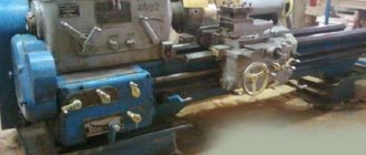
is a cutting tool designed for processing parts of various sizes, shapes, precision and materials. It is the main tool used for turning, planing and slotting work (and on corresponding machines).
To achieve the required dimensions, shape and accuracy of the product, layers of material are removed (sequentially cut) from the workpiece using a cutter. The cutter and the workpiece, rigidly fixed in the machine, come into contact with each other as a result of relative movement; the working element of the cutter is cut into the material layer and subsequently cut off in the form of chips. The working element of the cutter is a sharp edge (wedge), which cuts into the layer of material and deforms it, after which the compressed element of the material is chipped and shifted by the front surface of the cutter (chip flow surface). With further advancement of the cutter, the chipping process is repeated and chips are formed from individual elements. The type of chips depends on the machine feed rate, the rotation speed of the workpiece, the material of the workpiece, the relative position of the cutter and the workpiece, the use of coolant and other reasons.
During operation, the cutters are subject to wear (the cutting edges become dull, and in cutters with carbide plates, the cutting part is chipped), so they are re-sharpened.[⇨]
The main types of cutters[1] are now standardized.[⇨]
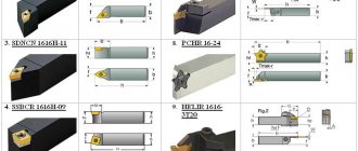
Cutter with mechanical fastening of a replaceable blade.
Elements of a turning tool
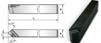
Elements of a turning straight cutter
Below are the elements of a cutter using the example of a turning straight cutter.
A turning cutter consists of the following main elements:
- Working part (head)
; - Rod (holder)
- serves to secure the cutter on the machine.
The working part of the cutter is formed by:
- The rake surface
is the surface along which chips flow during the cutting process. - The main flank surface
is the surface facing the cutting surface of the workpiece. - Auxiliary flank surface
is the surface facing the machined surface of the workpiece. - The main cutting edge
is the line of intersection of the front and main back surfaces. - Auxiliary cutting edge
is the line of intersection of the front and auxiliary back surfaces. - The tip of the cutter
is the intersection point of the main and auxiliary cutting edges.
Cutter angles and their purposes
The figure shows the main cutting plane
. The rake surface is directed downward from the main cutting edge, the rake angle γ in this case is considered positive.
To determine the cutter angles, the following planes are established:
- Cutting plane
- a plane tangent to the cutting surface and passing through the main cutting edge. - The main plane
is a plane parallel to the feed directions (longitudinal and transverse). - The main cutting plane
is a plane perpendicular to the projection of the main cutting edge onto the main plane. - Auxiliary cutting plane
is a plane perpendicular to the projection of the auxiliary cutting edge onto the main plane.
Principal angles are measured in the principal cutting plane. Sum of angles α+β+γ=90°
.
- The main clearance angle α
is the angle between the main clearance surface of the cutter and the cutting plane. Serves to reduce friction between the back surface of the cutter and the workpiece. As the clearance angle increases, the roughness of the machined surface decreases, but with a large clearance angle, the cutter may break. Therefore, the softer the metal, the larger the angle should be. - Point angle β
is the angle between the front and main back surfaces of the cutter. Affects the strength of the cutter, which increases with increasing angle. - The main rake angle γ
is the angle between the front surface of the cutter and a plane perpendicular to the cutting plane drawn through the main cutting edge.
Serves to reduce the deformation of the cut layer. With an increase in the rake angle, it is easier for the cutter to cut into the metal, cutting force and power consumption are reduced. Cutters with negative γ
are used for roughing work with impact load. The advantage of such cutters for roughing work is that impacts are absorbed not by the cutting edge, but by the entire front surface. - Cutting angle δ=α+β
.
measured in the auxiliary cutting plane.
Auxiliary relief angle α1, Auxiliary rake angle γ1, Auxiliary point angle β1, Leading angle φ, Auxiliary leading angle φ1, Leading angle ε, Main cutting edge angle λ
- Auxiliary clearance angle α1
is the angle between the auxiliary clearance surface of the cutter and the plane passing through its auxiliary cutting edge perpendicular to the main plane.
- Auxiliary rake angle γ1
- the angle between the rake surface of the cutter and the plane perpendicular to the cutting plane drawn through the auxiliary cutting edge
- Auxiliary sharpening angle β1
is the angle between the front and auxiliary rear planes of the cutter.
- Auxiliary cutting angle δ1=α1+β1
.
measured in the main plane. Sum of angles φ+φ1+ε=180°
.
- The main angle φ
is the angle between the projection of the main cutting edge of the cutter onto the main plane and the direction of its feed.
Affects tool life and cutting speed. The smaller φ
, the higher its durability and permissible cutting speed. However, this increases the radial cutting force, which can lead to unwanted vibrations. - Auxiliary angle φ1
is the angle between the projection of the auxiliary cutting edge of the cutter onto the main plane and the direction of its feed.
Affects the cleanliness of the treated surface. φ1
decreases , the surface cleanliness improves, but the friction force increases. - The apex angle in plan ε
is the angle between the projections of the main and auxiliary cutting edges of the cutter onto the main plane. Affects the strength of the cutter, which increases with increasing angle.
The main cutting edge is measured in a plane passing through the main cutting edge perpendicular to the main plane.
- The inclination angle of the main cutting edge λ
is the angle between the main cutting edge and a plane drawn through the tip of the cutter parallel to the main plane. Affects the direction of chip flow.
Cutter angles during cutting
When the cutter is displaced relative to the axis of the part, as well as in the presence of a feed movement, the cutting plane rotates, and therefore the angle values change.
If the tip of the cutter is set above or below the axis of the part, then the cutting plane will deviate from the vertical position by an angle τ. During external turning with the cutter installed above the axis of the part, the actual rake angle γoffset
increases, and
αdisplacement
decreases by angle
τ
. During internal turning, the angles change in the opposite direction.
With longitudinal feed, as a result of the rotational movement of the part and the translational movement of the cutter, the chips are cut along the helical surface. In this case, the cutting plane deviates from its static position by an angle μ. The larger the feed value, the greater the deviation. Rake angle in kinematics γkin
increases, and
αkin
decreases by angle
μ
. With a transverse feed, the cutting surface will be a spiral, and the clearance angle will decrease as the cutter approaches the axis of the part.
The actual value of the cutter angles in the main cutting plane, taking into account the installation of the cutter and the kinematics of the process, can be determined:
γд=γ+μ±τ
αд=α-μ±τ
The actual cutter angles are also affected by wear on the rake and flank surfaces of the cutter.
Design and purpose of the tool holder
The tool holder is a separate unit fixed with a bolt connection, used for fastening a metalworking tool. Significantly simplifies work with workpieces and allows for maximum bore holes. Tool holders are equipped with machine blocks that move the cutter.
At the top of caliper 1, on the centering collar, there is a tetrahedral head. On one side there is a cone-shaped retainer 5 with a spring 4, on the reverse side there is a ball retainer 17 with a plug on the thread 12 and a spring 15.
A flange 5 is attached to the top of the head 13 with bolts. On the middle finger 16 inside the head there is a fist 11, which has end teeth, as well as a ratchet clutch 10, which is pressed against the end of the fist by a spring 8. The clutch easily moves along the slots of the sleeve 9, pressed into the handle 7.
Handle 7 is used to release, rotate, install and secure the head. Release is carried out by turning the handle along the thread counterclockwise. Together with the handle, the fist 11, connected to it through the teeth of the ratchet 10, also moves. When the head is released under the influence of the bevel of the fist 11, the latch itself is raised on the tab of the latch 3, the knuckle 11 turns the head, resting the wall of the cutout against the pin 14. The ball 17 is raised at the same time . In the final stage of reversal, the locking ball falls into the next socket, preliminarily securing the head.
When the handle 7 is turned in the opposite direction, the fist 11 releases the latch 3, while it falls into slot 2 and finally secures the head. The wall of the cutout rests against the pin and stops the fist 11. Subsequent rotation of the handle 7 leads to the pressing of the ratchet 10 upward with the beveled end teeth. After turning the handle, the head and cutting tool are finally secured.
Classification of incisors
| The section lacks links to sources. Information must be verifiable or it may be deleted. You can edit the article to add links to authoritative sources. This mark was set on January 23, 2016 . |
In the direction of the incisors
there are:
- Right
. A right cutter is one in which, when the palm of the right hand is placed on top of it so that the fingers are directed towards its top, the main cutting edge will be under the thumb. On lathes, these cutters work when feeding from right to left, that is, to the headstock of the machine. - Left
. A left cutter is one in which, when the left hand is placed on it in the manner described above, the main cutting edge will be under the thumb.
By design
there are:
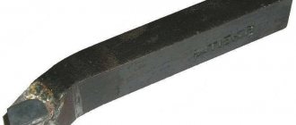
- Straight
- cutters in which the axis of the cutter head is a continuation or parallel to the axis of the holder. - Bent
- cutters in which the axis of the cutter head is inclined to the right or left of the axis of the holder. - Curved
- cutters in which the axis of the holder, when viewed from the side, is curved. - Retracted
- cutters whose working part (head) is narrower than the holder. - Designs of turners and innovative designers (special cases) and others
.
Trutnev designs
- with a negative rake angle γ, for processing very hard materials. - Merkulov’s designs
have increased durability. - Nevezhenko’s designs
have increased durability. - Shumilin's designs
- with radius sharpening on the front surface, are used at high processing speeds. - Lakura designs
have increased vibration resistance, which is achieved by the fact that the main cutting edge is located in the same plane with the neutral axis of the cutter rod. - Bortkevich design
- has a curved front surface, which ensures curling of chips and a chamfer that strengthens the cutting edge. Designed for semi-finishing and finishing processing of steel parts, as well as for turning and trimming ends. - The Seminsky boring cutter
is a high-performance boring cutter. - The Pavlov snail boring cutter
is a high-performance boring cutter. - Biryukov thread-cutting tool
. - Round cup self-rotating
.
Along the cross section of the rod
there are:
- rectangular
. - square
. - round
.
By manufacturing method
there are:
- solid
- these are cutters in which the head and holder are made of the same material. - composite
- the cutting part of the cutter is made in the form of a plate [2], which is attached in a certain way to a holder made of structural carbon steel. Carbide and rapid alloy plates are soldered or mechanically attached.
By type of material
there are:
- made of tool steel
.
made of carbon steel
. The designation of such steel begins with the letter U; it is used at low cutting speeds. - made of alloy steel
. The heat resistance of alloy steels is higher than that of carbon steels and therefore the permissible cutting speeds for cutters made of alloy steels are 1.2-1.5 times higher. - made of high-speed steel (high-alloy)
. The designation of such steel begins with the letter R (Rapid), cutters made from it have increased productivity.
. Cutters equipped with carbide inserts allow higher cutting speeds than cutters made of high-speed steel.
- metal-ceramic
.
tungsten
_ VK group alloys consist of tungsten carbide cemented with cobalt.
. TK group alloys consist of tungsten and titanium carbides cemented with cobalt.
. Alloys of the TTK group consist of tungsten, titanium and tantalum carbides cemented with cobalt.
. Materials based on technical alumina (Al2O3) have high heat resistance, but at the same time high fragility, which limits their widespread use.
- cermet
. The basis of these materials is mineral ceramics, but to reduce fragility, metals and metal carbides are introduced into it.
_ Based on cubic boron nitride.
.
By the nature of the installation relative to the workpiece
cutters can be of two types:
- radial
_ They work with installation perpendicular to the axis of the workpiece. They are widely used in industry due to the simplicity of their fastening and a more convenient choice of geometric parameters of the cutting part. - tangential
_ When a tangential cutter operates, the force Pr is directed along the cutter axis, due to which the cutter body is not subject to bending. It is used mainly on automatic and semi-automatic lathes, where the basis is cleanliness of processing.
By nature of processing
there are:
- roughing (roughing)
. - finishing
_ Finishing cutters differ from rough cutters by an increased radius of curvature of the tip, due to which the roughness of the machined surface is reduced. - fine turning cutters
.
By type of processing
According to their application on machines, cutters are divided into
- turning
- planing
- slotting
A cutter that removes chips during the rectilinear mutual movement of the cutter and the material is called planing (for horizontal cutting) or slotting (for vertical cutting). The nature of the work of planing and slotting cutters differs significantly from each other. On planing equipment, the cutter is tilted by an electromagnet at the moment of return, which eliminates friction of the cutter on the workpiece; in slotting, the table of the slotting machine synchronously removes the cutter from friction at the exit.
Turning cutters
- pass-through
- for turning workpieces along the axis of its rotation. - scoring
- for cutting ledges at right angles to the main direction of turning or for performing facings. - cutting
- for cutting workpieces at right angles to the axis of rotation or for cutting narrow grooves for a retaining ring, etc. - boring
- for boring holes. - chamfering
- for chamfering. - shaped
- for individual turning work.
When processing shaped parts, conventional turning tools do not provide accurate profile production and are low-productive. In large-scale and mass production, special shaped cutters are used as the main type of cutting tool for processing complex parts. They ensure identical shape ( pattern
), dimensional accuracy and high productivity. - slotted (groove)
- for the formation of grooves on the outer and inner cylindrical surfaces. - thread-cutting [3]
- for cutting threads.
Planing and slotting tools
- pass-through
- for planing the upper surface of the workpiece; - lateral
- trimming for planing parts from the sides; - cutting and slotting
- for cutting parts and cutting grooves; - cutters [4]
- slotting cutters for chiselling internal keyways in holes or internal splines;
What are holders
Manufacturers produce solid cutters for lathes and tools that require additional fastening. The first option, as a rule, is not suitable for metal processing. The holder is a part for attaching the cutter to the machine. You can screw any necessary equipment onto them: from rapid cutting steel, high-speed steel or tungsten carbide.
It is important to note that there is a large selection of tool holder cutters available that are significantly less expensive than a solid tool. Each tool has its own mount.
GOST standards
Designs and sizes
List of GOST standards for passing and scoring cutters
- GOST 18868-73 — Turning cutters, bent through, with plates made of high-speed steel. Design and dimensions
- GOST 18869-73 — Straight through lathe cutters made of high-speed steel. Design and dimensions
- GOST 18870-73 — Thrust-thrust lathe cutters made of high-speed steel. Design and dimensions
- GOST 18877-73 — Turning cutters, bent through, with hard alloy plates. Design and dimensions
- GOST 18878-73 — Straight turning cutters with hard alloy plates. Design and dimensions
- GOST 18879-73 — Thrust-type turning cutters with hard alloy plates. Design and dimensions
- GOST 18871-73 — Lathe scoring cutters with high-speed steel plates. Design and dimensions
- GOST 18880-73 — Lathe scoring cutters, bent with hard alloy plates. Design and dimensions
- GOST 26611-85 — Lathe cutters for passing, scoring and copying with fastening of replaceable plates with a clamp on top. Design and dimensions
- GOST 28980-91 — Lathe cutters for passing and scoring with replaceable cutting inserts made of superhard materials. Types and main sizes
- GOST 29132-91 — Turning cutters for passing, scoring and copying with replaceable multifaceted plates. Types and sizes
List of GOST standards for boring cutters
- GOST 9795-84 — Toolholder boring cutters with carbide alloy plates. Design and dimensions
- GOST 10044-73 — Boring cutters made of high-speed steel. Design and dimensions
- GOST 18062-72 — Solid carbide boring cutters with a steel shank for through holes. Design and dimensions
- GOST 18063-72 — Solid carbide boring cutters with a steel shank for blind holes. Design and dimensions
- GOST 18872-73 — Lathe boring cutters made of high-speed steel for machining through holes. Design and dimensions
- GOST 18873-73 — Turning boring cutters made of high-speed steel for machining blind holes. Design and dimensions
- GOST 18882-73 — Lathe boring cutters with hard alloy plates for machining through holes. Design and dimensions
- GOST 18883-73 — Lathe boring cutters with hard alloy plates for machining blind holes. Design and dimensions
- GOST 20874-75 — Prefabricated turning cutters with mechanical fastening of multifaceted carbide inserts. Design and dimensions
- GOST 25987-83 — Boring cutters with carbide inserts with a cylindrical shank for jig boring machines. Types and main sizes
- GOST 26612-85 — Boring cutters with fastening of replaceable plates with clamping on top. Design and dimensions
- GOST 28101-89 — Boring cutters with replaceable cutting inserts. Types and main sizes
- GOST 28981-91 — Lathe boring cutters with replaceable cutting inserts made of superhard materials. Types and main sizes
- GOST R 50026-92 — Lathe boring cutters with carbide inserts. Types and sizes
List of GOST standards for slotting and cutting tools
- GOST 18874-73 — Lathe slotting and cutting cutters made of high-speed steel. Design and dimensions
- GOST 18884-73 — Lathe cutting tools with hard alloy plates. Design and dimensions
- GOST 28978-91 — Prefabricated lathe cutters for slotting and cutting. Types and main sizes
List of GOST standards for thread-cutting tools
- GOST 18876-73 — Threaded turning cutters with high-speed steel plates. Design and dimensions
- GOST 18885-73 — Threaded turning cutters with hard alloy plates. Design and dimensions
List of GOST standards for planing and slotting cutters
- GOST 10046-72 — Slotting cutters made of high-speed steel. Design and dimensions
- GOST 18887-73 — Curved planing cutters with high-speed steel plates. Design and dimensions
- GOST 18888-73 — Wide curved finishing planing cutters with high-speed steel plates. Design and dimensions
- GOST 18889-73 — Planing scoring cutters, straight and curved, with high-speed steel plates. Design and dimensions
- GOST 18890-73 — Curved cutting and slotting cutters with high-speed steel plates. Design and dimensions
- GOST 18891-73 — Planing cutters with hard alloy plates. Design and dimensions
- GOST 18892-73 — Wide curved finishing planing cutters with hard alloy plates. Design and dimensions
- GOST 18893-73 — Planing scoring cutters with hard alloy plates. Design and dimensions
- GOST 18894-73 — Curved cutting and slotting cutters with hard alloy plates. Design and dimensions
Other GOSTs
- GOST 18875-73 — Lathe chamfering cutters made of high-speed steel. Design and dimensions
- GOST 18881-73 — Wide finishing turning cutters with hard alloy plates. Design and dimensions
- GOST 20872-80 — Prefabricated turning cutters for contour turning with mechanical fastening of multifaceted carbide inserts.
- GOST 24905-81 — Cutters for gear cutting heads for spur bevel gears. Design and dimensions
- GOST 24996-81 — Lathe cutters with mechanical fastening of replaceable inserts secured by a swinging pin. Types and main sizes
- GOST 29133-91 — Adjustable cutter inserts type A with replaceable multifaceted inserts. Types and sizes
Specifications
- GOST 5392-80 — Gear cutters for straight-toothed bevel wheels. Specifications
- GOST 5688-61 — Cutters with carbide inserts. Specifications
- GOST 10047-62 - High-speed steel cutters. Specifications
- GOST 13297-86 — Diamond cutters and inserts. Specifications
- GOST 17368-79 — Diamond cutters for profiling worm grinding wheels. Specifications
- GOST 18064-72 — Solid carbide boring cutters with a steel shank. Specifications
- GOST 26613-85 — Lathe cutters with mechanical fastening of replaceable polyhedral inserts. Specifications
- GOST R 50300-92 — Lathe cutters with replaceable cutting inserts made of superhard materials. Specifications
Designations
- GOST 26476-85 — Turning cutters and insert cutters with mechanical fastening of cutting interchangeable multifaceted inserts. Designations
- GOST 27686-88 — Boring cutters with mechanical fastening of cutting interchangeable multifaceted inserts. Designations
Advantages and disadvantages
Cutters with replaceable inserts have the following advantages:
- quick replacement of the main part of the part;
- Compliance with most machines and devices;
- the ability to quickly change cutting elements;
- wear resistance, high degree of reliability at high speeds;
- low price of components;
- commonality of cutting elements;
- increasing the service life of the cutter holder due to the use of removable elements made of hard alloys.
Among the shortcomings noted:
- high cost of imported parts compared to domestic ones;
- Incorrect fastening of the plate leads to damage to the tool and reduces its service life.
Sharpening and finishing of cutters
| External video files | |
| Tool sharpening and finishing | |
Wear of incisors can be divided into three periods in time. In the first period, increased wear is observed - this is breaking-in, erasing micro-irregularities on the surface of the cutting part remaining after the previous sharpening of the tool. During the second period, normal wear is observed - this is most of the operating time of the cutter. In the third period, catastrophic wear occurs. To use the tool rationally, it is necessary to resharpen it at the end of the second period.
Effective sharpening and finishing of cutters is achieved by the correct choice of abrasive material, level of technology and control. To sharpen a cutter, you need a material harder than the material of the tool. This material is an abrasive - grains of hard minerals. Grinding wheels consist of abrasives bonded with a special bond and can have a different structure. It is determined by the percentage and mutual arrangement of grains, binders and pores in the mass of the circle. When sharpening cutters, wheels with a medium (numbers 6-10) or open (numbers 11-18) structure are used. Diamond wheels are used to sharpen carbide cutters. Sharpening and finishing of cutters is carried out on various types of sharpening machines.
Sharpening machine.
When sharpening new cutters, as a rule, the back surfaces are sharpened first, and then the front surfaces. The front surfaces are processed in two operations: 1) preliminary sharpening over the entire surface at the angle of soldering of the plate to the holder 2) final sharpening along a limited area of the front edge at an angle γ (chamfer sharpening). The shape of the front surface of the cutters depends on the material being processed, cutting conditions and material of the cutting part. Sharpening a chamfer (0.2...0.3 mm) along the main cutting edge strengthens it. Curved radius sharpening along the main cutting edge facilitates deformation and chip removal. Radial grooves on the front surface are machined to break off or curl chips. Sharpening of the rear auxiliary surface is carried out in three operations: 1) 12° 2) 10° 3) 8°. Finally, the tip of the cutter is sharpened along the radius.
To increase the durability of cutting tools, they are fine-tuned after sharpening. It improves the cleanliness of the sharpened surface and removes the layer of defects formed during sharpening.
The sharpening angles of cutters for wood and metal are different[5]
DIY holder design options
Despite the variety of designs, you can make a tool holder yourself from materials available in any garage or home workshop.
Homemade tool holders used for “garage” work are not subject to increased requirements for the accuracy of tool fastening, and you can save a significant amount for other needs. Video:
What tool holder is installed on your machine? Have you tried to make it yourself at home? Please share your opinion and experience in the comments.
Literature
- A. M. Dalsky and others.
Technology of structural materials. - M.: Mechanical Engineering, 1977. - 664 p. - Kozhevnikov D.V., Kirsanov S.V.
Metal cutting tools. Textbook (UMO stamp). Tomsk: Tomsk University Publishing House. 2003. 392 p. (250 copies). - Kozhevnikov D.V., Kirsanov S.V.
Cutting materials. Textbook (UMO stamp). M.: Mechanical engineering. 2007. 304 p. (2000 copies). - Lectures by Vladimir Viktorovich Podgorkov (Doctor of Technical Sciences, Prof. Department of TAM, Ivanovo State Energy University)