Interchangeability of parts.
The production of bicycles, motorcycles, tractors, cars, electric motors, sewing and other machines is carried out at factories at such a pace that processing and assembly time is counted not only in minutes, but also in seconds. The parts of these machines must be manufactured exactly according to drawings and technical specifications so that during assembly they fit one another without metal fitting, which reduces assembly time and reduces the cost of the product. It is also important that when repairing a machine, a new part replacing a worn one can be installed in its place without adjustment. Parts that meet such requirements are called interchangeable . Interchangeability is the ability of parts to take their places in assemblies and products without prior selection or adjustment in place.
Pairing parts.
Two parts that are movably or stationarily connected to each other are called mating . The dimensions along which these parts are connected are called mating dimensions . Dimensions for which parts are not connected are called free dimensions . An example of mating dimensions is the outer diameter of the milling mandrel and the corresponding diameter of the hole in the mounted cutter, the diameter of the mandrel neck and the corresponding diameter of the hole in the suspension bearing. An example of free dimensions is the outer diameter of the milling mandrel mounting rings, the length of the milling mandrel, and the width of the cylindrical cutter.
The mating parts must be made interchangeable.
Classification of lathes according to main and auxiliary characteristics
Turning (turning) is intended for the mechanical formation of the geometry of mechanical engineering parts with a blade tool by removing chips. The cutting kinematics is determined mainly by the relative rotational movement of the workpiece with a spatially fixed axis of rotation and an arbitrary feed movement. The objects of processing are most often coaxial surfaces of rotation and flat surfaces of parts such as shafts, disks and bushings, including cutting external and internal threaded surfaces, as well as surfaces of some other shapes, such as non-circular ones, by introducing additional relative movement of the tool [36]. The shapes of surfaces obtained by turning methods are given in table. 1.12.1.
Classification of machines of the turning group only by technological characteristics is insufficient due to the new capabilities provided by CNC devices in technological and design terms, therefore it is advisable to use characteristics that reflect the design and specific features of lathes, namely: the main design feature; auxiliary species character; layout; number of positions for securing workpieces; number of installed tools; type of management; accuracy class [20].
The classification of machines according to main and auxiliary characteristics is given in table. 1.12.2.
The layout of the machines is determined by the position of the main axis of rotation of the workpiece and the relative position of the tool in the spatial coordinate system used in ISO recommendation R-841. Based on this feature, horizontal and vertical layouts are distinguished.
The level of concentration of operations performed on one machine is characterized by the number of working positions and the method of securing workpieces (single- and multi-spindle cartridge; single- and multi-spindle collet (bar); single- and multi-spindle center; combined), as well as the conditions that determine the effectiveness of the tool used : the number and complexity of the shapes of the processed surfaces with different feed directions; number of different types of instruments; possibilities of spatial orientation of tools relative to the workpiece; comparability of surface treatment times.
Based on the number of positions for securing workpieces, single- or multi-spindle designs are distinguished, and based on the number of tools installed, machines are single- or multi-seat, multi-tooled and with a tool magazine.
In this regard, special attention is paid to the concentration of turning operations, the creation of multi-purpose lathes that combine off-center drilling, some milling and other similar operations. At the same time, measures are taken to reduce off-cycle losses associated with readjustment, control, loading and unloading, tool changing and others, which is possible with a developed CNC-based machine control system [4].
1.12.1. Typical surfaces obtained by turning
- External round cylindrical surface shape
- External longitudinal cylindrical turning: the axis of rotation of the workpiece and the feed line are parallel;
- External transverse round turning: the axis of rotation of the workpiece and the feed line are mutually perpendicular;
- External centerless turning: longitudinal cylindrical turning with several rotating tools with a small auxiliary entering angle at high feed rates
- Internal longitudinal circular boring: the workpiece rotation axis and the feed line are parallel;
- Internal longitudinal drilling (countersinking, reaming): the axis of rotation of the workpiece and the axis of the tool coincide;
- Internal transverse circular boring of a groove: the axis of rotation of the workpiece and feed are mutually perpendicular in a certain area
- External (internal) round double-sided turning with arbitrary feed using a combination of methods 1.1, 1.2 and 2.1, 2.3
- External longitudinal turning with displacement of one of the machine centers;
- External longitudinal turning with rotation of tool guides;
- External longitudinal turning with guide ruler;
- External cross turning with a tool with a wide inclined cutting edge
- Internal longitudinal boring is similar to methods 4.2, 4.3, transverse boring - to method 4.4
- External longitudinal helical turning with a single-tooth tool with a feed equal to the pitch and a cutting edge profile corresponding to the thread profile;
- The same, with a multi-toothed tool (threaded comb);
- The same, with a multi-toothed enclosing tool (die);
- External longitudinal cutting with multi-tooth rotating tool;
- External longitudinal female milling with multi-tooth tools;
- External longitudinal screw turning with an arbitrary pitch equal to the feed, according to method 4.1;
- External transverse screw turning of end spirals with an arbitrary pitch equal to the feed and thread profile according to method 16;
- External longitudinal external milling with multi-flute tool
- Internal longitudinal cutting with a single-tooth tool, the profile of the cutting edge of which corresponds to the profile of the thread root;
- Internal longitudinal cutting with a multi-toothed tool (tap) coaxial to the axis of rotation of the workpiece with a feed equal to the thread pitch of the tap
- External transverse undercutting feed direction is perpendicular to the axis of rotation of the workpiece;
- External longitudinal undercut turning; the main cutting edge of the tool is perpendicular to the axis of rotation of the workpiece;
- External slot turning
- Internal transverse undercutting is similar to methods 8.1 and 8.3, longitudinal undercutting according to 8.2
- External transverse cutting with profile tools;
- External longitudinal turning with a rotating profile tool;
- External copy turning with controlled feed movement, e.g. CNC
- External slotted non-circular turning with controlled feed movement;
- External longitudinal non-circular turning under the same conditions
1.12.2. Classification of machines according to main and auxiliary characteristics
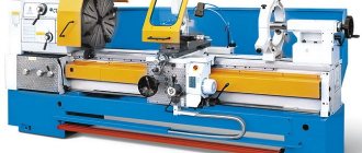
- Lathes and screw-cutting lathes
- Universal turning screw cutters
- Cartridge and cartridge-center
- Cartridge-rod and cartridge-center rod
- Tabletop
- Transverse and longitudinal turning
- Single spindle programmable
- Single spindle vertical
- Multi-spindle horizontal with rotating workpieces
- Multi-spindle horizontal with rotating tools
- Multi-spindle vertical
- Frontal
- Horizontal turret
- Vertical turret
- Multi-incisor
- Hydrocopying
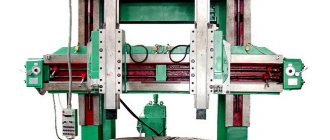
- Single post
- Double post
- Frontal
- Simple
- Universal
- Nut-threading
- Threading
- Thread lathes
- For processing turbine wheels, liners, cylinders, pipes, crankshafts, etc.
Features of determining the straightness of guides (4.5)
1 Convex guide
A guide is considered convex if all its points are located above a straight line connecting the ends of the guide.
2 Local deviation from straightness
The deviation from straightness between two points of the guide, spaced from each other at a given base length, less than the length of the guide, defined as the difference in the vertical coordinates (ordinates) of these points, is called the local deviation from straightness.
Local deviation between points a
and
b
at a given length
l
is equal to
h
2 -
h
1 (Figure B.1).
Figure B.1
3 Option of guides in the form of a normal convex curve
Tolerances for local deviations are set to eliminate significant errors at short lengths.
For conventional guides, which are made in the form of a convex curve that is approximately symmetrical about the middle, local tolerances are too tight for the ends of the guides. In this case, on the final sections of the guides, equal to one quarter of their length, the local tolerance values can be doubled.
Classification of lathes by degree of automation
The degree of automation is the ratio of the time of automatic transitions to the total processing time of the product on the machine.
The capabilities and classification of modern lathes by degree of automation are given in table. 1.12.3.
1.12.3. Classification of lathes by degree of automation
- Manual control
- Installation of workpiece and tool, positioning of working parts and formation of basic cycles manually. Automated positioning of working bodies and formation of basic cycles
- Semi-automatic control
- Consistency of manually generated basic cycles. Partial manual modification of basic cycle stages. Free modification of basic cycles with manual tool replacement
- Arbitrary automatic change of basic cycles with tool replacement. Arbitrary automatic change in the order of execution of basic cycles with a corresponding change in the order of operation of the tool. The same, including manipulations with the workpiece and the processed part. Fully automatic organization of the part manufacturing cycle
Classification of lathes by accuracy
Accuracy is the degree of approximation of the actual values of the product parameters to the ideal parameters.
Accuracy is assessed by the actual error or limits limiting the error values (normalized accuracy).
Machine errors directly affect processing accuracy.
The accuracy of machine tools is regulated by state (industry) standards, which generally contain five accuracy classes.
The distribution of the main types of turning machines by accuracy class is given in Table. 1.12.4. Special and specialized machines are not covered in the table.
Technical and technological indicators of lathes are determined by a set of components and their components, the main of which are reflected in table. 1.12.5.
1.12.4. Accuracy classes and main types of turning machines
| Main types of machines | N | P | IN | A | C |
| Lathes and screw-cutting machines | + | + | + | + | + |
| Semi-automatic and automatic turning machines | + | + | + | — | — |
| Turning turrets | + | + | + | + | — |
| Lathe copying machines | + | + | — | — | — |
| Carousel and frontal | + | + | + | — | — |
| Backing and thread processing | + | + | + | + | — |
| Multi-purpose, specialized and special | — | + | + | + | — |
Relationships (coefficients) between wholesale prices for machines of different accuracy classes according to GOST 8-82
| Base | N | P | IN | A |
| Accuracy class "N" normal | 1,0 | 1,13 | 1,4 | 2,0 |
| Accuracy class "P" increased | — | 1,0 | 1,25 | 1,75 |
| Accuracy class "B" high | — | — | 1,0 | 1,4 |
| Accuracy class “A” is especially high | — | — | — | 1,0 |
Diagnostics of CNC machines
Modern methods of diagnosing CNC machines are a set of works aimed at examining the target equipment and identifying a malfunction - failure or malfunction. Diagnostics is carried out in two stages:
- Checking the condition of the machine makes it possible to identify structural causes of failure - as a rule, we are talking about the breakdown of some component or part. Partial or complete disassembly of the unit may be required.
- Checking a numerical control system involves diagnosing the machine by testing the control program. Test results and errors are displayed using special codes.
The first stage of checking machines requires the use of specific tools - levels, indicators, gauges, protractors, micromeasures. At the control program verification stage, the engineer uses backplot or solid-state verification, simulating the operation of the machine, and then conducts a final check on the equipment.
Checking machines for accuracy:
The specifics of equipment diagnostics are determined, among other things, by the purpose, for example, checking a lathe for accuracy is a strictly regulated set of diagnostic procedures aimed at confirming the correspondence of the data in the passport with real data. In this case, it is necessary to check the following parameters:
- Movement of elements holding the workpiece.
- The arrangement of the surfaces on which the workpiece and tool are based.
- Matching the shape of the base surfaces.
Also, checking a machine for geometric accuracy includes assessing the trajectory of movements, angular and linear movements of machine parts, and it is possible to evaluate other parameters. All accuracy requirements are specified in the equipment passport, and errors are identified based on the relevant GOST standards, for example, GOST 8-82 and GOST 18097-93.
Please note that checking machines for technological accuracy is dictated by the natural wear and tear of the equipment during operation. We are not talking about wear of cutters, drills or cutters
Permanent components of the machine are diagnosed, for example:
- drives;
- calipers;
- consoles;
- spindles.
Checking a machine for accuracy, provided it has a CNC, also involves diagnosing measuring devices that are necessary for implementing the control program and automatically processing workpieces. As a result of the check, the possibility of further use of the diagnosed machine in this area is determined. In case of a critical error, equipment is repaired, modernized or replaced.
Machine diagnostics regulations:
The schedule for routine diagnostics of machine tools is drawn up based on the list of machine equipment. This document includes information about the operating mode of the machine and all operations that affect its accuracy.
Diagnostics of CNC machines can be carried out not only in a planned manner, but also in emergency mode - this scenario is determined by the relevant regulations developed specifically for force majeure circumstances.
Please note that since all inspections are carried out under conditions of temporary equipment decommissioning, drawing up an inspection schedule is a complex and important undertaking that takes into account all aspects of the production activities of the workshop and the enterprise as a whole. As a rule, this schedule is drawn up by the chief technologist of the plant
Diagnostics of different types of machines and individual components:
Obviously, milling machine inspection and lathe inspection are two separate sets of procedures, the differences between which are due to differences in equipment design. Also, in some cases, it is not the entire machine that requires inspection, but a specific unit.
For example, checking the tailstock of a lathe evaluates the reliability of fixation in the selected position and the accuracy of movement in the direction of the spindle while maintaining alignment during rotation. Ensuring the reliability of fastening and stability determines the class of processing accuracy.
Today, our specialists have enough experience and are properly qualified to implement modern diagnostic methods for CNC machines of all types. We perform scheduled and emergency checks, evaluate the performance and accuracy of individual components, and diagnose control programs. We provide a guarantee for all types of work performed, and provide free consultations on any issues.
Types of equipment errors
Geometric errors.
They characterize errors in the relative position of machine components and depend on the quality of manufacturing and assembly of the machine. The accuracy of a product in terms of geometric parameters is a collective concept, divided according to the following criteria:
- dimensional accuracy of elements
- roughness accuracy
- precision of the shape of element surfaces
- accuracy of relative position of elements
Kinematic accuracy
Affects the speed of movement of the working parts of the equipment and shape formation during gear processing; they are a consequence of errors in screw pairs, gears, variable stiffness of units, etc.
- Elastic errors
- Temperature errors
- Dynamic errors are associated with vibrations.
- Wear errors during operation (friction)
- Instrument errors.
REQUIREMENTS FOR TEST METHODS
3.1. Methods and measuring instruments must comply with GOST 22267, this standard, standards for accuracy standards for specific types of machine tools and technical specifications.
It is allowed to use testing methods and measuring instruments that differ from those specified in the standards for machine tool accuracy standards, provided that the required measurement accuracy is met and the reliability of the determination of the verified accuracy parameters is ensured.
Methods for checking the accuracy of machine tools, specified in the standards for specific types of machines and technical specifications as preferable, become mandatory in the event of disagreements between the manufacturer and the consumer.
(Changed edition, Amendment No. 2).
3.2. The measurement error should not exceed the values given in the standards for accuracy standards for specific types of machine tools. If such instructions are absent, then the measurement error, as a rule, should not exceed 30% of the tolerance of the measured value.
(Changed edition, Amendment No. 3).
3.3. The error introduced when processing numerical measurement data is an integral part of the error according to clause 3.2 and should not exceed 0.1 of the measurement error.
3.4. When choosing verification methods, preference should be given to those whose results directly characterize the verified accuracy parameter without additional calculations.
3.5. Measuring instruments used to check the accuracy of machine tools must be certified. Measuring instruments must be standardized to the temperature of the working space. If necessary, the influence of temperature on the measurement results is corrected.
3.6. The location of the control parts of the mandrels must provide the ability to measure deviations at the lengths to which the tolerances are assigned. The dimensions of the control parts of the mandrels are indicated in Appendix 3.
The control mandrels must have a surface hardness of at least 53 HRC and a roughness of the control parts of no more than 0.32 microns according to GOST 2789.
3.7. When installing a control ruler over 500 mm long in a horizontal plane onto two plane-parallel gauge blocks (tiles) of the same height, their distance from the ends of the ruler should be approximately the length of the ruler.
3.8. When determining the accuracy of the position or movement of the working body of the machine relative to a surface with insufficient shape accuracy, measurements are taken from a plane parallel to the adjacent one. It is allowed to use a surface plate or a ruler located on the surface.
3.9. In order to exclude from the measurement results deviations in the shape and location of the working surfaces of the measuring instruments (for example, deviations from the straightness and parallelism of the working surfaces of the straight edge or the generatrices of the control mandrel, deviations of the perpendicularity measuring instrument, etc.), it is allowed to carry out measurements in such a way that the specified deviations were compensated.
3.10. The tolerance value is equal to the largest permissible algebraic difference between the extreme readings of measuring instruments, with the exception of cases provided for in the standards for accuracy standards of machine tools of specific types and technical conditions.
If the same test gives different tolerances for an accuracy parameter for different measurement lengths, the tolerance assigned to the shorter length (smaller tolerance) applies to any portion of the measurement length.
(Changed edition, Amendment No. 3).
3.11. When carrying out measurements, the magnitudes and directions of permissible deviations established in the standards for accuracy standards of machine tools of specific types and technical conditions must be taken into account.
Technical and technological indicators of turning machines
1.12.5. Technical and technological indicators of turning machines
- Basic operating conditions
- Dimensions of the working space for placing workpieces, tools and fixtures.
- The location of the surfaces to be processed, their number and dimensions.
- The largest mass of installed workpieces and methods of fastening.
- Limits of rotation speeds and feeds of working bodies
- The basic shape of the workpieces being processed (determines the spatial placement of the working parts of the machine).
- Number, shape and parameters of installed tools for standard processing methods.
- Number of controlled (including simultaneous) movements of working bodies.
- Discreteness of movement along coordinate axes
- Main drive and feed power.
- Number of transitions and passes.
- Speeds of idle and installation movements.
- The same working movements.
- Availability of automation of main and auxiliary cycles.
- Equipped with additional accessories and devices.
- Number of simultaneously processed workpieces and installed tools
- Output accuracy of the machine.
- Accuracy of product installation and stability of positioning of working parts.
- Initial workpiece accuracy and volumetric quality stability.
- Dimensional wear resistance of the tool.
- Static, dynamic and thermal deformations of the supporting system, groups of workpiece units and tools.
- Possibility of correcting the movements of forming elements.
- Character of wear of machine elements and components
- Machine weight.
- The area occupied by the machine.
- Reliability of systems and components.
- Specific energy intensity.
- Material consumption.
- Technical and operational safety and efficiency.
- Ease of management and maintenance.
- Maintainability
GOST 8-82
STATE STANDARD OF THE USSR UNION
METAL CUTTING MACHINES
GENERAL REQUIREMENTS FOR ACCURACY TESTS
GOST 8-82
USSR STATE COMMITTEE FOR PRODUCT QUALITY CONTROL AND STANDARDS
Moscow
STATE STANDARD OF THE USSR UNION
| METAL CUTTING MACHINES General requirements for accuracy tests Metal-cutting machine tools. General requirements to accuracy tests | GOST 8-82 |
Date
of introduction 07/01/83
Failure to comply with the standard is punishable by law
This standard applies to metal-cutting machines, including machines with numerical control, electrophysical and electrochemical, machine accessories, assembly units tested separately from the machines, manufactured for the needs of the national economy and export.
The standard establishes the basic concepts and principles for classifying machine tools by accuracy, general requirements for accuracy testing and general requirements for accuracy testing methods.
The requirements of this standard are mandatory, except for paragraphs. 1.9, 2.4, 2.14, 2.15, 3.4, 3.8, 3.9.
(Changed edition, Amendment No. 1,).
1. BASIC PROVISIONS
1.1. The accuracy of metal-cutting machines is determined by three groups of indicators:
indicators characterizing the accuracy of processing of product samples;
indicators characterizing the geometric accuracy of machine tools;
additional indicators.
1.2. Indicators characterizing the processing accuracy of product samples include:
accuracy of geometric shapes and location of processed surfaces of product samples;
constancy of batch sizes of product samples;
roughness of processed surfaces of product samples.
1.3. Indicators characterizing the geometric accuracy of the machine include:
accuracy of bases for installing workpieces and tools;
accuracy of movement trajectories of the working parts of the machine, carrying the workpiece and tool;
accuracy of the location of the axes of rotation and directions of linear movements of the working parts of the machine, carrying the workpiece and tool, relative to each other and relative to the bases;
accuracy of interconnected relative linear and angular movements of the working parts of the machine, carrying the workpiece and tool;
accuracy of dividing and installation movements of the working parts of the machine;
accuracy of coordinate movements (positioning) of the working parts of the machine, carrying the workpiece and tool;
the stability of some parameters with multiple repetitions of the test, for example, the accuracy of approach to a hard stop, the accuracy of small approach movements.
1.4. Additional indicators of machine accuracy include the ability to maintain the relative position of the working parts of the machine carrying the workpiece and tool, provided:
application of external load (stiffness indicators);
exposure to heat generated when the machine is idling;
machine vibrations that occur when the machine is idling.
(Changed edition, Amendment No. 2).
1.5. The scope of testing machines for accuracy should be minimal, but sufficient to obtain the necessary reliability of test results and assess the accuracy of the machine.
1.6. When choosing the accuracy parameters to be tested, preference should be given to the most significant of them, taking into account the degree of reproducibility of measurement results, stability and accuracy of measurement.
1.7. The list of machine tool accuracy indicators is determined by the standards for accuracy standards of machine tools of specific types and technical conditions.
1.8. The accuracy standards of a machine after medium and major repairs must comply with the requirements of the standards and technical conditions in force during the period of manufacture of the machine.
1.9. Classification of machines by accuracy
1.9.1. Five accuracy classes of machine tools are established according to the absolute classification system, designated in order of increasing accuracy level: N, P, B, A and C.
The division of machine tools into accuracy classes is carried out by type of machine, based on the requirements for processing accuracy.
The same accuracy class should include machines that provide the same processing accuracy of sample product surfaces corresponding in shape and size.
For certain types of machines intended only for grinding work, accuracy classes are not established.
(Changed edition, Amendment No. 1,).
1.9.2. The tolerance values of accuracy indicators when moving from one accuracy class to another are preferably taken according to a geometric series with a denominator j = 1.6. For specific indicators of geometric accuracy, it is allowed to take other values of j from 1.0 to 2.0.
(Changed edition, Amendment No. 3).
1.9.3. Accuracy classes for individual types of machine tools should be established in the standards for accuracy standards for these types of machine tools, and in the absence of standards, in the technical specifications for the machines.
1.9.4. Deleted
.
2. REQUIREMENTS FOR ACCURACY TESTS
2.1. Each machine manufactured at the manufacturing enterprise and each machine that has undergone medium and major repairs must be tested for accuracy.
If state standards for accuracy standards for machine tools of specific types contain instructions to test for rigidity, then it is carried out during acceptance and, if necessary, during periodic tests.
(Changed edition, Amendment No. 2,).
2.2. The accuracy test of the machine should be carried out when the machine is finally assembled.
2.3. Before testing for accuracy, installation of the machine, alignment of the machine and, if necessary, tightening of foundation bolts must be carried out in accordance with the instructions given in the operational documents for the machine, developed in accordance with GOST 2.601-68. In this case, the requirements for the foundation and installation of the machine on it must be observed.
Permissible deviations when aligning a machine by level are selected in accordance with standards for accuracy standards for specific types of machine tools, technical specifications or operational documents for the machine. If there are no such instructions, then the permissible deviations when aligning the machine to the level should not exceed 0.04 mm/m for machines of accuracy classes N and P and 0.02 mm/m for machines of a higher accuracy class.
In this case, the working parts of the machine, carrying the workpiece and the tool, must be in the middle working position. When aligning a machine with two or more working elements on one guide, the working elements should be positioned symmetrically in the middle of the guide, unless the standards for accuracy standards for specific types of machine tools and technical conditions contain special instructions.
The position of the levels when aligning specific machine models is established according to the operational documents for the machine.
(Changed edition, Amendment No. 1, 2).
2.4. Assembly units of machines are checked on stands.
2.5. Testing of the machine for accuracy by the manufacturer must be carried out after testing the machine at idle speed and in operation in accordance with GOST 7599-82 and after making the necessary adjustments in accordance with the regulatory and technical documentation for the machine.
When testing a machine for accuracy, only adjustments are allowed that are provided for by the standards for accuracy standards of machine tools of specific types, technical conditions and testing methods.
2.6. Inspections of individual assembly units and parts that cannot be carried out on finished machines without disassembling them must be carried out by the manufacturer during their manufacture and assembly, recording the results in the operational documents for the machine.
Machine tools should not be disassembled when testing for accuracy.
It is permissible to remove casings, shields, chucks, steady rests, mandrels, centers and other removable accessories to the machine, if this does not affect its accuracy.
2.7. Machine tools transported disassembled should be tested for accuracy at the consumer's site after their final assembly, alignment and adjustment.
2.8. In the process of testing machines for accuracy, the sequence of checks can be changed, but you should first check the surfaces and movements, which serve as the basis for subsequent checks.
2.9. When testing for accuracy, the moving components of the machine must be in the positions specified in the standards for accuracy standards for specific types of machine tools and technical conditions.
2.10. Testing of machines for accuracy in operation should be carried out by processing sample products. The dimensions, shapes and requirements for the base and machined surfaces of product samples must comply with GOST 25443-82 standards for accuracy standards for specific types of machine tools and technical conditions.
When testing automatic machines, a batch of sample products must be processed, the volume of which must meet the requirements of standards for accuracy standards for machine tools of specific types and technical conditions.
(Changed edition, Amendment No. 2,).
2.11. Fluctuations in the temperature of the working space during the period of testing machines for accuracy should not exceed the values specified in the standards for accuracy standards of machine tools of specific types, in technical specifications or in operational documents for machines.
If such instructions are absent, then for machines of accuracy classes B, A and C, fluctuations in the temperature of the working space should not exceed 2 °C. For machines of accuracy classes N and P, temperature fluctuations in the working space are not regulated.
When testing, machines must be protected from air flows, thermal radiation and other heat sources.
2.12. If the test result is significantly influenced by the heat generated during operation of the machine, then this test should be carried out after the machine is idling in accordance with the instructions of the standards for accuracy standards for specific types of machine tools, technical conditions, methods for checking accuracy parameters and operational documents for machines.
It is allowed to carry out these checks without preheating. In this case, the deviation from the initial position corresponding to the normal temperature of the machine should be normalized.
2.13. The required movements of the working bodies and other elements of the machine must be carried out manually or mechanically at speeds provided for in the technical specifications and other regulatory and technical documentation for the machine.
2.14. When testing for rigidity, a load that gradually increases to a given limit is applied to parts of the machine that carry the tool and the workpiece, and the relative movement of these parts is simultaneously measured.
2.15. The maximum permissible movements (lower limits of rigidity) of machine components carrying the tool and workpiece under certain loading forces are accepted as the rigidity indicators normalized in the standards.
2.16. All parts that need to be moved when testing for stiffness must be brought into the testing position by moving them in the direction opposite to the direction of the force component acting on them during testing.
2.17. Stiffness test conditions should approximate the loading conditions of a typical type of processing.
2.18. Standards that include testing of hardness must specify the testing conditions, including:
a) diagrams of the position of components and machine parts during the inspection process;
b) directions and magnitudes of loading forces and the point of their application;
c) directions and points at which movements should be measured;
d) methods for specifying loading forces and means of measuring them;
e) methods and means of measuring movements.
2.19. Special loading devices or machine mechanisms must be used as loading devices.
2.14 — 2.19. (Introduced additionally, Amendment No. 2).
3. REQUIREMENTS FOR TEST METHODS
3.1. Methods and measuring instruments must comply with GOST 22267-76, this standard, standards for accuracy standards for specific types of machine tools and technical specifications.
It is allowed to use testing methods and measuring instruments that differ from those specified in the standards for machine tool accuracy standards, provided that the required measurement accuracy is met and the reliability of the determination of the verified accuracy parameters is ensured.
Methods for checking the accuracy of machine tools, specified in the standards for specific types of machines and technical specifications as preferable, become mandatory in the event of disagreements between the manufacturer and the consumer.
(Changed edition, Amendment No. 2).
3.2. The measurement error should not exceed the values given in the standards for accuracy standards for specific types of machine tools. If such instructions are absent, then the measurement error, as a rule, should not exceed 30% before the start of the measured value.
(New edition, Amendment No. 3).
3.3. The error introduced when processing numerical measurement data is an integral part of the error according to clause 3.2 and should not exceed 0.1 of the measurement error.
3.4. When choosing verification methods, preference should be given to those whose results directly characterize the verified accuracy parameter without additional calculations.
3.5. Measuring instruments used to check the accuracy of machine tools must be certified. Measuring instruments must be standardized to the temperature of the working space. If necessary, the influence of temperature on the measurement results is corrected.
3.6. The location of the control parts of the mandrels must provide the ability to measure deviations at the lengths to which the tolerances are assigned. The dimensions of the control parts of the mandrels are indicated in Appendix 3.
The control mandrels must have a surface hardness of at least 53 HRCe and a roughness of the control parts of no more than Ra
0.32 microns according to GOST 2789-73.
3.7. When installing a control ruler over 500 mm long in a horizontal plane on two plane-parallel gauge blocks (tiles) of the same height, their distance from the ends of the ruler should be approximately 2/9 of the length of the ruler.
3.8. When determining the accuracy of the position or movement of the working body of the machine relative to a surface with insufficient shape accuracy, measurements are taken from a plane parallel to the adjacent one. It is allowed to use a surface plate or a ruler located on the surface.
3.9. In order to exclude from the measurement results deviations in the shape and location of the working surfaces of the measuring instruments (for example, deviations from the straightness and parallelism of the working surfaces of the straight edge or the generatrices of the control mandrel, deviations of the perpendicularity measuring instrument, etc.), it is allowed to carry out measurements in such a way that the specified deviations were compensated.
3.10. The tolerance value is equal to the largest permissible algebraic difference between the extreme readings of measuring instruments, with the exception of cases provided for in the standards for accuracy standards of machine tools of specific types and technical conditions.
If the same test gives different tolerances for an accuracy parameter for different measurement lengths, the tolerance assigned to the shorter length (smaller tolerance) applies to any portion of the measurement length.
(Changed edition, Amendment No. 3).
3.11. When carrying out measurements, the magnitudes and directions of permissible deviations established in the standards for accuracy standards of machine tools of specific types and technical conditions must be taken into account.
APPENDIX 1, 2.
Excluded.
APPENDIX 3
Recommended
Dimensions of control parts of mandrels, mm
| Length of the control part of the mandrel | Cantilever mandrel | Center mandrel | ||
| Outside diameter | Inner diameter | Outside diameter | Inner diameter | |
| 75 | 12 | — | — | — |
| 150 | 25 | — | 25; 40 | — |
| 200 | 32 | 23 | 32; 40 | — |
| 300 | 40 | 30* | 40 | — |
| 500 | 63 | 44* | 63 | 50 |
| 80 | 60* | — | — | |
| 1000 | — | — | 80 | 61 |
| 1600 | — | — | 125 | 105 |
* Average hole diameter.
APPENDIX 4.
Deleted.
INFORMATION DATA
1. DEVELOPED AND INTRODUCED by the Ministry of Machine Tool and Tool Industry
PERFORMERS
B.S. Vasiliev
, Doctor of Technical Sciences
sciences; A.N. Bankov,
Ph.D. tech. sciences;
S.S. Kedrov
, Ph.D.
tech. sciences; N.V.
Sokolova ;
N.V.
Shporin 2. APPROVED AND ENTERED INTO EFFECT by Resolution of the USSR State Committee on Standards dated September 23, 1982 No. 3728
3. The inspection period was 1992.
4. INSTEAD GOST 8-77
5. The standard fully complies with ST SEV 3111-81, ST SEV 3112-81, ST SEV 3115-81
The standard includes the requirements of the international standard ISO R 230
6. REFERENCE REGULATIVE AND TECHNICAL DOCUMENTS
| Designation of the referenced technical document | Item number, application |
| GOST 2.601-68 | 2.3 |
| GOST 2789-73 | 3.6 |
| GOST 7599-82 | 2.5 |
| GOST 22267-76 | 3.1 |
| GOST 25346-89 | 3.10, Appendix 4 |
| ST SEV 3111-81 | 1.9.1, appendices 1, 2 |
7. REISSUE (November 1989) with Amendments No. 1, 2, approved in February 1988, in October 1989 (IUS 5-88, 1-90)
CONTENT
| 1. Basic provisions. 1 2. Requirements for accuracy tests. 3 3. Requirements for verification methods. 5 |