The cutting tools used in the metalworking process wear out (regardless of the brand of hardware) quite quickly, and are quite expensive. If you use a carbide insert in conjunction with a turning cutter, you can solve several problems at the same time, and in general significantly increase the productivity of a piece of equipment.
This article will help you understand the types of carbide inserts for turning tools and some of the features of working with them.
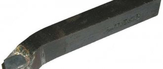
Replaceable carbide inserts are not used in metalworking using monolithic cutters, in which the holder and cutting part are a single unit.
general information
For the manufacture of all models of attachments for cutters, only alloys characterized by an improved formula are used - AL 20 (40) and AP 25 (40) . The geometry of any sample is thought out to the smallest detail. This allows the corresponding technological operations to be carried out with maximum accuracy and in a short time, with a significant reduction in the percentage of defects.
Existing standards
Carbide inserts come in several types. A detailed description of each of them can be found in the relevant GOST.
- 19042 from 1980. This standard defines the designation system, categorization and requirements for the shape of carbide inserts (replaces GOST under the same number from 1973).
- 19086 from 1980. This document outlines all the characteristics of chipbreakers, as well as replaceable attachments of the supporting and cutting type.
- 25395 from 1990. GOST applies to the type of carbide inserts that are fastened to the holders of through-cutting, boring and revolving cutters by soldering (01, 61, 02 and 62).
Designation of replaceable polyhedral inserts
According to GOST 19042-80, replaceable multifaceted inserts (SMP) are classified into cutting, supporting and chipbreakers.
To designate replaceable polyhedral plates, a special 10-digit code is used, but, as a rule, the first 7 digits are used to designate plates.
The first four digits can be indicated by letters or numbers:
- plate shape;
- rear corner;
- tolerance class or manufacturing accuracy of platinum;
- design features of the plate (type).
The next three digits are indicated by a six-digit number (separated by a dash):
- plate size;
- working plate thickness;
- The shape of the vertex (or the size of the vertex radius).
The following designations are not mandatory, but may be specified at the request of the manufacturer:
- cutting edge design (letter);
- cutting direction (letter);
- manufacturer's special designations.
What are the benefits of using carbide inserts for cutters?
- Versatility of use of one turning tool. By changing carbide inserts, it is possible to process metals and alloys characterized by different composition, structure and hardness. If you have the necessary set of attachments on hand, then problems with metalworking associated with finding and reinstalling the necessary tool will not arise. This is especially true for automated production facilities with a large range of products.
- Savings. The plate costs much less than the cutter. If the cutting part breaks, you do not have to replace the entire tool. In addition, the service life of its housing increases by more than 20 times compared to a soldered analogue.
- Changing (rotating) the insert takes less time than reinstalling the cutter. And this is one of the components of increasing productivity.
- The attachments allow you to change the cutting mode over a wide range, which creates convenience in work, increases its speed and quality.
- Large assortment of nozzles. Selecting the right insert for each technological operation is much easier than the tool itself. For small industries (especially household lathes), it is more profitable to have a certain set of attachments than to purchase a large number of cutters of various types.
What can you do with carbide inserts?
- Surface treatment of workpieces.
- Thread cutting.
- Internal boring.
- Scan.
- Sampling of grooves, grooves and the like.
- Cut out the materials. For example, sheet glass, getinax, non-ferrous metals.
Types of carbide inserts - explanation of markings, designations, classification
Content:
- Grades of carbide inserts for turning
- An example of deciphering the markings of a turning plate
- Marking of threaded plates
- An example of deciphering the markings of a threaded plate
- Marking of carbide cutting and groove inserts
- Marking of milling inserts
- An example of decoding the markings of a milling plate
There is a huge variety of carbide inserts for turning and milling machines on the market today. Understanding the markings of plates, their types, shapes and sizes, even for a non-novice in turning, is not an easy task. In this article we will try to sort out all the carbide inserts, especially those presented in our online store.
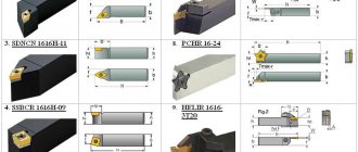
Carbide inserts for specific tools
This characteristic is one of the simplest - the plates are placed on turning tools, drills or milling cutters, which means that this is the purpose we choose.
Turning plates are also easy to understand.
By purpose they are:
- Turning inserts
- Parting and grooving
- Threading Inserts
Turning inserts are selected for specific holders (cutters). You need to know such characteristics as the size and shape of the carbide insert, the grade of the insert, its radius, mode and type of turning (from roughing to finishing). Also, before purchasing replacement inserts, you need to decide what materials this alloy is suitable for processing. There are more universal alloys, and there are narrowly targeted plates.
How to understand the markings of carbide inserts
Grades of carbide inserts for turning
There are many standards and manufacturers, on average the plate markings are more or less the same (for example, according to ISO), there are slight variations among some brands. You need to “read” the insert from left to right; the name of the interchangeable tool says a lot - shape, angles, tolerances, length of the cutting edge, shape of the chipbreaker, etc.
The tables below provide explanations for the designation of turning plates .
Designations of the main GESAC chip breakers:
The letters and numbers after the chipbreaker designation indicate the type of alloy from which the tool is made. Here, each manufacturer has its own traditional designations.
An example of deciphering the markings of a turning plate
For clarity, let's decipher the turning insert CNMG090304-QF GP1115 from GESAC.
Let's look at the first four letters - CNMG . C – rhombus, N – clearance angle 0°, M – height tolerance limit +/- 0.08-+/- 0.18 mm; thickness +/- 0.13; the size of the inscribed circle is d +/- 0.05-+/- 0.13 and G indicates that the plate has a hole.
Let's go further - the numbers 090304 in the name of the plate “say” that the length of the cutting edge is 9.52 mm (09), the thickness of the plate is 3.18 mm (03) and the corner radius is 0.4 mm (04). The chipbreaker is at the insert in the example QF, which means that it is intended for finishing of steel and steel-based alloys. The most recent designation in the marking is alloy GP1115.
You can always seek advice from CNCMagazine managers to select the right tools for turning and milling machines in Kazakhstan. Write to us by E-mail: . Phone in Pavlodar +7-705-894-51-07 (+ WhatsApp).
Marking of threaded plates
The designation of replacement inserts for thread cutting is easy to understand. The major manufacturers of carbide inserts have more or less the same markings.
Below is a table to decipher the name of the threaded plate :
Threaded inserts are available for cutting internal and external threads, usually in right-handed or left-handed versions. An important characteristic of the tool is the thread profile. The CNCMagazine online store offers a tool with the following profile :
- ISO metric thread full profile
- Thread partial profile 60° and 55°
- Whitworth Pipe Thread
- British BSPT pipe thread for steam, gas and water pipes
- American Tapered Pipe Thread (NPT)
- American ABUT profile
- Trapezoidal thread 30°
- API thread (round)
- American UN thread, full profile
Each profile has its own standards, recommendations, and technical characteristics.
Let us take an example of the markings of a carbide insert for thread cutting.
An example of deciphering the markings of a threaded plate
Let's take a 16ER0.75ISO DM215 plate. 16 is the plate size (9.525 mm). ER in the marking indicates that the insert is intended for cutting external threads, right-handed. The following number - 0.75 means that the thread pitch is 0.75 mm. ISO - indicates that the thread standard is metric according to ISO. The last thing in the name is the alloy from which the tool is made.
Carbide insert codes often overlap between different manufacturers. Most often, only the names of the alloys used differ.
Marking of carbide cutting and groove inserts
brands of tools for cutting and grooving , as well as manufacturers. Different brands have their own markings. To quickly and easily decipher the purpose of the tool and find out its characteristics, look at the tables below.
Let's try to decipher the plate ZTFD0303-MG YBG202 . ZT means the tool is designed for grooving and turning, F means the insert is 3.0 wide, and D means it's a double-sided insert. 03 – cutting edge width is 3 mm, and apex radius is 0.3. M is the accuracy grade and G means the insert has a conventional chipbreaker. YBG202 is an alloy.
A breakdown of triangular-shaped cutting plates for processing straight and radius grooves from one Chinese brand is presented below.
Marking of milling inserts
Replaceable inserts for cutters come in trigonal (W), square (S), round (R), octagonal (O), rhombic 86° (M), rectangular 85° (A), pentagonal (P) and other shapes (Z). The shape of the cutter plate can be recognized by the first letter in the name. The second letter is the clearance angle of the insert, followed by the accuracy class, then the insert type. The first number after the letters in the name of the insert is the length of the cutting edge in mm.
Then comes the thickness of the plate, also in mm. You can tell the nose radius by the name of the milling insert.
As an example, let's look at the markings of milling inserts from the manufacturer SANDVIK.
An example of decoding the markings of a milling plate
APKT11T308-APM YB9320 cutters using this diagram
Insert shape – rectangular, relief angle 11°, accuracy class K, insert size 11, radius 0.8, alloy YB9320.
On our website, each product is described in detail, its characteristics, recommended types of processing, materials, etc. are indicated.
If you find it difficult to choose the right tool for metal turning and milling, we are always happy to help you.
We are waiting for your questions and requests for metalworking tools: by E-mail, by phone in Pavlodar +7-705-894-51-07 (+ WhatsApp) or fill out the application below.
Online store
SEND YOUR APPLICATION
Features of using carbide inserts
Dimensions – in mm.
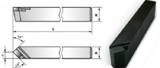
- Primary sharpening of the cutting edge is carried out at the manufacturer. Since it gradually wears out, the product simply turns over, that is, its other face, previously unused, becomes working. Therefore, there is no need to systematically sharpen the edge, which is typical for brazed turning tools.
- For rough processing of workpieces, thicker plates (up to 6) with long edges (up to 25) are used. Technological operations called finishing (for example, grinding) are performed with small products. Their minimum dimensions are: length – 7, thickness – 3.
Manufacturers of quality carbide inserts
Judging by the reviews of amateurs and professionals on thematic websites, there are no significant complaints about the products of the following manufacturers.
- Ceratizit (Luxembourg).
- Proxxon, BDS-Machinen (Germany).
- Ukrainian "Instrument-Service".
What to consider when choosing replacement nozzles
It is understood that they are purchased as a set, but without a cutter.
- Correspondence of linear parameters of tool and inserts.
- Specifics of product use. If metalworking involves removing significant layers from the workpiece, then you should select attachments whose material is inert to high temperatures. Working at high speeds is accompanied by increased vibrations. In this case, you need to pay attention to such characteristics of the samples as resistance to loads (mechanical).
- Type of parts processing. This already comes to the question of the required shape of the nozzles.
Polyhedral plate shape
Based on their form, SMPs are divided into 4 groups.
- Equilateral and equiangular plates (Fig. 1).
This group includes plates that have the shape of a regular polygon or circle. H - hexagon, O - octagon, P - pentagon, R - circle, S - square, T - triangle.
- Equilateral and unequal-angled plates (Fig. 2).
This group includes plates in the shape of an irregular hexagon (W) and a rhombus with an angle = 80, 55, 75, 86, 35 degrees and the designation C, D, E, M, V, respectively.
- Non-equilateral and equiangular plates (Fig. 3).
The third group includes plates shaped like a rectangle.
- Non-equilateral and non-equiangular plates (Fig. 4).
These include SMP in the form of a parallelogram with an angle = 85, 82, 55, 84 degrees and the designation A, B, K, F, respectively. Inserts of this shape can be produced with one of four types of cutting edges: sharp, rounded, chamfered and rounded with chamfer.
Cost of carbide inserts
They are sold in sets, so the price depends on the configuration, shape, size and a number of other indicators. In addition, they may also include cutter bodies, which increases the cost. If we talk about its average value, then a kit without tools will cost 5,310 rubles, and with it – about 7,980.
In principle, it’s not that expensive, considering that, according to experts, the use of replaceable attachments gives a monthly saving of about 450 rubles on one lathe (with average equipment load).
Designation of inserts / ISO insert designation chart
Interpretation of the designation of replaceable cutting inserts according to the ISO standard Part 1 Turning tools Insert shape Hexagonal Octagonal Pentagonal
Decoding of the designation of replaceable cutting inserts according to the ISO standard Part 1 Turning tools Insert shape Hexagonal Octagonal Pentagonal _ Square Triangular c Rhombic 80 o D Rhombic 55 Z7 E Rhombic 75 o F Rhombic 50 7 M Rhombic 86 V Rhombic 35 Z7 W Three-tone L Rectangular o A Rhombic 85 o B Rhombic 82 o K Rhombic 55 R Round O X Special design Insert shape designation AG 0D1 S1 Triangular chamfered insert (Auxiliary cutting Tolerance class designation Features of tolerance of class M inserts Tolerance for cutting edge height m (mm) (Kime Height tolerance cutting edge m (mm) Inscribed circle diameter tolerance 0D1 (mm) Insert thickness tolerance S1 (mm) Triangular Square Rhombic 80 Rhombic 55 Rhombic 35 Round A 0.005 0.025 +0.025 F 0.005 0.013 +0.025 6.35 0.08 0.08 0.08 0.11 0.16 C 0.013 0.025 +0.025 9.525 0.08 0.08 0.08 0.11 0.16 N 0.013 0.013 +0.025 12.70 0.13 0.13 0.13 0.15 E 0.025 0.025 +0.025 15.875 0.1 5 0.15 0.15 0.18 G 0.025 0.025 +0.13 19.05 0.15 0.15 0.15 0.18 J 0.005 0.05 0.15 +0.025 25.40 0.18 K 0.013 0.05 0.15 +0.025 31.75 0.20 1 +0.025 +0.05 +0.15 +0.025 Tolerance for piston circle diameter (ft w) M 0.08 0.18 0.05 0.15 0.13 Circular Triangular Square Rhombic 80 Rhombic 55 Rhomb ical 35 Round N 0.08 0.18 0.05 0.15 0.025 The sign indicates the surfaces of the sintered plates. 12.70 0.08 0.08 0.08 0.08 - 0.08 15.875 0.10 0.10 0.10 0.10 - 0.10 19.05 0.10 0.10 0.10 0.10 - 0.10 25.40 - 0.13 - 0.13 31.75 - 0 .15 - 0.15 Designation of tolerance class C N M G Designation of rear angle INN Standard angle A 3 B 5 C 7 15 E 20 F 25 -JV G 30 N 0 P 11 O Other angle values Main angles used Chipbreaker fixation designation Metric system Presence of hole Hole shape Chipbreaker Fig. Both Presence of hole Hole shape Chipshopper Fig. W With a cylindrical hole + one countersink (40-60) No I 1 I A With a cylindrical hole No 1111 1 With a hole One-sided GI1 VH7 With a cylindrical hole One-sided VI 17 Q With a cylindrical hole + two countersinks (40-60) No G With a hole cylindrical double-sided and with hole double-sided N Carried hole. — No B With a cylindrical hole + one countersink (70-90) No P7 R Without holes. — Single-sided GIG 7 With Hole Single-sided F Without hole. — double-sided rm VM7 LJ With a cylindrical hole + two countersinks (70-90) No X — Special design J With a double-sided hole A002 DESIGNATION OF PLATE FOR TURNING
Advantages of using turning inserts
Inserts for cutting or boring cutters are produced on the basis of different grades of carbide alloys. This is very convenient, since it will allow you to equip yourself with a large set of cutting elements that will process workpieces made from different elements.
And the use of replaceable turning devices for a cutting tool can confidently be called a profitable solution from an economic point of view, since if a breakdown or wear occurs, there will be no need to change the entire cutter, only its cutting part. It is best to use a tool equipped with replaceable carbide inserts when it is necessary to automate technological processes. This is especially important for small and medium-scale production of various products.
Carbide products that are placed on turning tools have a number of advantages:
- they are cheaper compared to solid incisors;
- you can replace the carbide cutting element with a new one very quickly;
- plates based on hard alloys are highly reliable even under intensive use;
- if necessary, such replaceable cutting parts can be readjusted;
- All existing models of these cutting elements for cutters are unified, so you can easily select the appropriate option for a particular type of processing, as well as the grade of material of the workpiece being processed.
And the use of replaceable carbide inserts equipped with mechanical fastening can significantly increase the service life of the turning tool holder, and there is also no need to sharpen and solder the cutting part. In addition, under the conditions of use of this tool, the temperature and cutting force can be reduced by up to 40 percent. Carbide alloys have such properties that they can be used for the production of plates, and they can be used to process metals, subject to changing cutting conditions.
Currently, different types of carbide products are produced. The requirements for each type are specified in state standards. They are presented below:
- GOST 19086–80 - implies the characteristics of support and cutting plates, as well as chipbreakers;
- GOST 19042–80 - prescribes the requirements for the shape, classification, as well as the designation system for replaceable inserts based on carbide materials;
- GOST 25395–90 regulates the production of several types of carbide inserts; they are fixed to the cutter holder by soldering. This applies to elements connected by soldering to turret, pass-through or boring cutters.
Tolerance class
According to GOST 19042-80, there are 12 tolerance classes of replaceable plates: A (6), F, C (4), H, E (5), G (3), J, K (7), L, M (2), N, U (1).
Plate type or design features
- According to the number of working edges, SMPs are: one-sided - R, M; double-sided - N, A, F, G.
- According to the shape of the front edge (the presence of chip-breaking grooves), the replacement inserts are: without chip-breaking grooves (with a flat edge) - N, A, W; with chip-breaking flutes - R, M, F, G, T.
- Based on the presence of holes, SMPs are divided into: without holes - N, R, F; with hole - A, M, G, W, T.