What is a transformer?
In short, this is a stationary device used to convert alternating voltage while maintaining the frequency of the current. The operation of the transformer is based on the properties of electromagnetic induction.
Some historical facts
The operation of the transformer was based on the phenomenon of magnetic induction, discovered by M. Faraday in 1831. The physicist, working with direct electric current, noticed a deflection of the needle of a galvanometer connected to one of two coils wound on the core. Moreover, the galvanometer reacted only at the moments of switching the first coil.
Since the experiments were carried out from a direct current source, Faraday could not explain the discovered phenomenon.
The prototype of the transformer appeared only in 1848. It was invented by the German mechanic G. Ruhmkorff, calling the device an induction coil of a special design. However, Ruhmkorf did not notice the transformation of the output voltages. The date of birth of the first transformer is considered to be the day the patent was issued to P. N. Yablochkov for the invention of a device with an open core. This happened on November 30, 1876.
Types of devices with closed cores appeared in 1884. They were created by the Englishmen John and Edward Hopkinson.
By and large, the technical interest of electromechanics in alternating current arose only thanks to the invention of the transformer. The ideas of the Russian electrical engineer M. O. Dolivo-Dobrovolsky and the world famous Nikola Tesla won the debate about the advantages of alternating voltages precisely because of the possibility of current transformation.
With the victory of the ideas of these great electrical engineers, the need for transformers increased sharply, which led to their improvement and the creation of new types of devices.
How to choose a power transformer
The choice of power transformer for operation in enterprises is based on the selection of power, as well as in accordance with the requirements for power reliability. To ensure uninterrupted power supply, in some cases it is necessary to install several transformers. The power of each device is selected in such a way that if it fails, other devices are able to take over the functions of this missing link, taking into account possible overloads.
Another important criterion is the availability of protection:
- From internal damage. Provided with devices that monitor the presence of gases, temperature, pressure and oil cooler level;
- From overloads. The so-called differential protection is used when current transformers are installed on each phase.
General structure and principle of operation
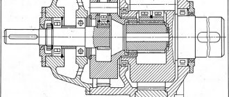
Let's consider the design of a simple transformer with two coils mounted on a closed magnetic circuit (see Fig. 2). The coil that receives current will be called the primary coil, and the output coil will be called the secondary coil.
Figure 2. Transformer design
Virtually all types of transformers use electromagnetic induction to convert the voltage entering the primary winding circuit. In this case, the output voltage is removed from the secondary windings. They differ only in shape, magnetic core materials and methods of winding the coils.
Ferromagnetic cores are used in low-frequency models. The following materials are used for such cores:
- steel;
- permalloy;
- ferrite.
In some high-frequency models, magnetic cores may be absent, and in some products materials made from high-frequency ferrite or alsifer are used.
Due to the fact that the characteristics of ferromagnets are characterized by nonlinear magnetization, the cores are assembled from sheet materials onto which windings are placed. Nonlinear inductance leads to hysteresis, to reduce which the method of lamination of magnetic circuits is used.
The core shape can be W-shaped or toroidal.
Basic principles of operation
When a sinusoidal current is supplied to the terminals of the primary windings, it creates an alternating magnetic field in the second coil that penetrates the magnetic circuit. In turn, a change in the magnetic flux provokes the induction of an emf in the coils. In this case, the magnitude of the EMF voltage in the windings is proportional to the number of turns and the frequency of the current. The ratio of the number of turns in the primary winding circuit to the number of turns of the secondary coil is called the transformation ratio: k = W1 / W2, where the symbols W1 and W2 indicate the number of turns in the coils.
If k > 1, then the transformer is step-up, and if 0 < k < 1, then the transformer is step-down. For example, when the number of turns that make up the primary winding is three times less than the number of secondary turns, then k = 1/3, then U2 = 1/3 U1.
Transformers and their applications
A transformer is a device used to increase or decrease alternating voltage without changing its frequency and with virtually no power loss. A transformer consists of two or more coils mounted on a common core. The coil that is connected to the AC voltage source is called primary, and the coil to which the load (consumers of electrical energy) is connected is called secondary. Transformer cores are made of electrical steel and assembled from separate plates insulated from each other (to reduce energy losses due to the occurrence of eddy currents in the core).
Transformer coils typically contain different numbers of turns, with more voltage being applied to the coil with more turns. If a transformer is used to increase voltage, the winding with fewer turns is connected to the voltage source, and the winding with more turns is connected to the load. To lower the voltage, everything is done the other way around. At the same time, we should not forget that no more than the rated voltage (the one for which it is designed) can be applied to the primary winding.
The transformation ratio is the ratio of the number of turns in the primary winding to the number of turns in the secondary winding. It is also equal to the ratio of the EMF in the windings. In the absence of losses in the windings, the transformation coefficient is equal to the ratio of the voltages at the winding terminals: k=U1/U2. For a step-down transformer, the transformation ratio is greater than 1, and for a step-up transformer, it is less than 1. The operating principle of the transformer is based on the phenomenon of electromagnetic induction. When alternating current flows through the primary coil, an alternating magnetic field and magnetic flux arise around it, which also penetrates the second coil. As a result, a vortex electric field appears in the secondary coil and an induced emf appears at its terminals.
The transformer is characterized by an efficiency equal to the ratio of the power released in the secondary coil to the power consumed by the primary coil from the network. Good transformers have an efficiency of 99 - 99.5%. An important property of a transformer is its ability to transform load resistance. Consider a transformer with an efficiency of approximately 100%. In this case, the power released in the secondary circuit of the transformer will be equal to the power consumed by the primary winding from the voltage source. For such a transformer, the power consumed from the voltage source will be purely active. Power in the primary circuit of the transformer P1=(U12)/R1, and in the secondary circuit P2=(U22)/R2.
It will be interesting➡ Idle mode for transformers
Since P1=P2 and U1=kU2, then R1=k2R2.
Thus, a load with resistance R2 connected to an alternating voltage source through a transformer will be equivalent in power to a load with resistance R1 connected without a transformer. Laboratory autotransformers are widely used to regulate alternating voltage. Autotransformers are designed for connection to an alternating voltage network of 220 V or 127 V. As a rule, the output voltage of the autotransformer is smoothly regulated up to 250 V.
The transformer winding is made of insulated wire in one layer. In areas of the winding that are touched by the moving contact with the carbon insert, the insulation is cleaned. When the contact moves, the carbon insert short-circuits a turn of wire. However, due to the small voltage on one turn and the noticeable resistance of the carbon insert, an allowable current flows through the closed turn.
The primary winding of an autotransformer is part of its secondary winding and therefore there is a galvanic connection between the primary and secondary windings of the transformer. Consumers cannot be directly connected to the secondary winding of the autotransformer, one of the wires of which may be connected to ground. This connection will lead to an accident or mishap. When working with an autotransformer, it is prohibited to ground the secondary circuit. Let us briefly consider the simplest calculation of low-power transformers for household radio equipment.
The power of the transformer (in W) is numerically equal to the square of the area (in cm2) of the cross section of the middle core of the magnetic core. Knowing the rated power of the transformer, you can find the current in the primary winding at the rated load in the secondary windings. The diameter of the winding wire is selected based on (2.5-3) A/mm2 of the wire cross-section. For standard magnetic cores used for the manufacture of transformers, the number of turns per 1 volt is approximately equal to the quotient of 50 divided by the cross-sectional area of the central core of the magnetic core, expressed in cm2. However, depending on the quality of the magnetic core, the coefficient can vary from 35 to 65.
Transformer.
The total resistance of an inductor with a ferromagnetic core depends on the strength of the current flowing through it. The resistance of the coil, depending on the strength of the flowing current, first increases, reaches a maximum value, and then decreases. The nonlinear increase in no-load current depending on the voltage applied to the primary winding begins at approximately 0.8 Un. The rated voltage of the primary winding of the transformer is selected so that the no-load current is 5-10% of the rated current. At a voltage of 1.1 Un, the no-load current should not exceed 20-25% of the rated current of the loaded transformer.
Material on the topic: how a toroidal transformer works and what are its advantages.
Operating modes
The characteristics of transformers are determined by operating conditions, where the load resistance plays a key role. The following modes are used as a basis:
- Idle move. The outputs of the secondary circuit are in an open state, the load resistance is equal to infinity. Measuring the magnetizing current flowing in the primary winding makes it possible to calculate the efficiency of the transformer. Using this mode, the transformation ratio is calculated, as well as losses in the core;
- Under load (working). The secondary circuit is loaded with a certain resistance. The parameters of the current flowing through it are directly related to the ratio of the turns of the coils.
- Short circuit. The ends of the secondary winding are short-circuited, the load resistance is zero. The mode informs about losses that are caused by heating of the windings, which in professional language is referred to as “copper losses”.
Short circuit mode
Information about the behavior of the transformer in various modes is obtained experimentally using equivalent circuits.
Idling speed (XX)
This operating procedure is implemented by opening the secondary network, after which the flow of electric current in it stops. An no-load current flows in the primary winding; its component element is the magnetizing current.
When the secondary current is zero, the electromotive force of induction in the primary winding completely compensates for the voltage of the supply source, and therefore, when the load currents disappear, the current passing through the primary winding corresponds in its value to the magnetizing current.
The functional purpose of idle operation of transformers is to determine their most important parameters:
- efficiency;
- transformation indicator;
- losses in the magnetic circuit.
Load mode
The mode is characterized by the operation of the device when voltage is applied to the inputs of the primary circuit and a load is connected to the secondary circuit. The loading current flows through the “secondary”, and in the primary - the total load current and the no-load current. This operating mode is considered predominant for the device.
The question of how a transformer operates in the main mode is answered by the basic law of induced emf. The principle is this: applying a load to the secondary winding causes the formation of a magnetic flux in the secondary circuit, which forms a loading electric current in the core. It is directed in the direction opposite to its flow, created by the primary winding. In the primary circuit, the parity of the electromotive forces of the electricity supplier and induction is not respected; in the primary winding, the electric current is increased until the magnetic flux returns to its original value.
Short circuit (SC)
The device switches to this mode when the secondary circuit is briefly closed. A short circuit is a special type of load, the applied load - the resistance of the secondary winding - is the only one.
The principle of operation of a transformer in short-circuit mode is as follows: a slight alternating voltage comes to the primary winding, the terminals of the secondary are short-circuited. The input voltage is set so that the value of the closing current corresponds to the value of the rated electric current of the device. The voltage value determines the energy losses due to heating of the windings, as well as active resistance.
This mode is typical for measuring type devices.
Based on the variety of devices and types of purposes of transformers, we can confidently say that today they are indispensable devices used almost everywhere, thanks to which stability is ensured and the voltage values required by the consumer are achieved, both in civil networks and industrial networks.
Repair and service
A transformer is a complex piece of equipment. Periodic maintenance and repair will be required. It is recommended to entrust this work to professionals. Only a person with appropriate training has the right to carry out such work.
With an increased heating rate and the presence of noise, it is necessary to rewind the transformer circuits. This procedure can only be performed by an unqualified specialist with a minimum level of knowledge in the field of electrical engineering.
The device has a magnetic drive. It is common to coils. The first circuit is responsible for reducing, and the second circuit is responsible for increasing electricity in the network. Inspection of the transformer is carried out using a certain technology.
Examination
First, a visual inspection of the block is carried out. If overheating is observed during operation, deformations, irregularities, and swelling of the insulation appear on the surface. If the inspection does not reveal any deviations, you need to find the input and output of the device. The first of them is connected to the first coil. This is where a magnetic field appears when electricity is supplied. The output is connected to the secondary winding.
The output signal is filtered. This indicator needs to be measured. The collapsible parts of the housing structure are removed. You need to gain access to the microcircuits. This will allow you to measure the voltage with a multimeter. In this case, you will need to take into account the nominal indicators. If the measurement result is less than 80% of the value specified by the manufacturer, the primary circuit is not functioning correctly.
The first coil is disconnected from the device. It no longer receives electricity. Then the secondary circuit is checked. If there is no filtering, power from the measuring device is used. If there is no normal voltage in the system, the equipment requires repair.
After checking, if the component elements are in good condition, the structure is assembled in the reverse order. If necessary, the unit is repaired.
Principle of operation
The operating principle of the transformer is based on the effect of mutual induction. The supply of a variable frequency current from a third-party electricity supplier to the inputs of the primary winding forms a magnetic field in the core with a variable flux passing through the secondary winding and inducing the formation of an electromotive force in it. Short-circuiting the secondary winding at the electricity receiver causes an electric current to pass through the receiver due to the influence of the electromotive force, and at the same time a load current is generated in the primary winding.
The purpose of the transformer is to move converted electrical energy (without changing its frequency) to the secondary winding from the primary with a voltage suitable for the functioning of consumers.
Connection diagrams
Connection diagrams for single-phase voltage transformers:
Connection diagrams for three-phase voltage transformers:
Diagrams and groups of connections of windings of three-phase three-winding transformers with main and additional secondary windings
Also read: Features and why sovtol transformers are being replaced
Design
The transformer design assumes the presence of one or more individual coils (tape or wire), located under a single magnetic flux, wound on a core made of a ferromagnet.
The most important structural parts are as follows:
- winding;
- frame;
- magnetic circuit (core);
- cooling system;
- insulation system;
- additional parts necessary for protective purposes, for installation, to provide access to the output parts.
In devices you can most often see two types of winding: the primary, which receives electric current from an external power source, and the secondary, from which the voltage is removed.
The core provides improved return contact of the windings and has reduced magnetic flux resistance.
Some types of devices operating at ultrahigh and high frequencies are produced without a core.
The production of devices is established in three basic winding concepts:
- armored;
- toroidal;
- core.
The design of core transformers involves winding the winding onto the core strictly horizontally. In armor-type devices it is enclosed in a magnetic circuit and placed horizontally or vertically.
Reliability, operational features, design and principle of operation of the transformer are taken without any influence from the principle of its manufacture.
Transformer winding made of aluminum wire (main sizes):
| Winding symbol | Transformer type | Side | Connection diagram | Voltage, kV | Overall dimensions, mm | ||
| Height | Inner diameter | Outer diameter | |||||
| B 4-25-10/0.4 | TM-25/10 | VN | Y/Y0-0 | 10 | 328 | 135 | 199 |
| VN 4-25-10/0.4 | 304 | 150 | 205 | ||||
| VN 4-40-10/0.4 | TM-40/10 | 392 | 160 | 230 | |||
| VN 4-40-10/0.4 | 344 | 160 | 241 | ||||
| VN 4-63-10/0.4 | TM-63/10 | 418 | 160 | 250 | |||
| VN 4-100-10/0.4 | TM-100/10 | 504 | 190 | 266 | |||
| VN 4-160-10/0.4 | TM-160/10 | 492 | 210 | 301 | |||
| VN 4-250-10/0.4 | TM-250/10 | 527 | 235 | 324 | |||
| VN 4-400-10/0.4 | TM-400/10 | 595 | 255 | 355 | |||
| VN 4-630-10/0.4 | TM-630/10 | 629 | 295 | 412 | |||
| NN 4-25-0.4/6-10 | TM-125/10 | NN | 0,4 | 328 | 90 | 127 | |
| NN 4-25-0.4/6-10 | 304 | 96 | 132 | ||||
| NN 4-40-0.4/6-10 | TM-40/10 | 392 | 107 | 146 | |||
| NN 4-40-0.4/6-10 | 344 | 106 | 144 | ||||
| NN 4-63-0.4/6-10 | TM-63/10 | 418 | 118 | 149 | |||
| NN 4-100-0.4/6-10 | TM-100/10 | 504 | 128 | 181 | |||
| NN 4-160-0.4/6-10 | TM-160/10 | 492 | 147 | 201 | |||
| NN 4-250-0.4/6-10 | TM-250/10 | 527 | 163 | 225 | |||
| NN 4-00-0.4/6-10 | TM-400/10 | 595 | 188 | 246 | |||
| NN 4-630-0.4/6-10 | TM-630/10 | 629 | 212 | 285 | |||
| VN 4-25-6/0.4 | TM-25/6 | VN | 6 | 328 | 135 | 199 | |
| VN 4-40-6/0.4 | TM-40/6 | 392 | 160 | 230 | |||
| VN 4-63-6/0.4 | TM-63/6 | 418 | 160 | 252 | |||
| VN 4-100-6/0.4 | TM-100/6 | 504 | 190 | 265 | |||
| VN 4-160-6/0.4 | TM-160/6 | 492 | 210 | 303 | |||
| VN 4-20-6/0.4 | TM-250/6 | 527 | 235 | 319 | |||
| VN 4-400-6/0.4 | TM-400/6 | 595 | 255 | 357 | |||
| VN 4-630-6/0.4 | TM-630/6 | 629 | 295 | 410 | |||
| VN 4-25-10/0.4 | TM-25/10 | VN | 10 | 290 | 145 | 208 | |
| VN S*-25-10/0.4 | 320 | 135 | 194 | ||||
| VN S-25-10/0.4 | 320 | 140 | 205 | ||||
| NN S-25-0.4/10 | NN | 0,4 | 290 | 95 | 135 | ||
| NN S*-25-0.4/10 | 320 | 91 | 124 | ||||
| NN S-25-0.4/10 | 320 | 90 | 130 | ||||
| VN S-40-6/0.4 | TM-40/6 | VN | 6 | 337 | 155 | 230 | |
| VN S-40-10/0.4 | TM-40/10 | 10 | 337 | 159 | 216 | ||
| NN S-40-0.4/6-10 | NN | 0,4 | 337 | 105 | 144 | ||
| VN S-100-10/0.4 | TM-100/10 | VN | 10 | 540 | 160 | 234 | |
| NN S-100-0.4/10 | NN | 0,4 | 540 | 115 | 148 | ||
| VN S-160-10/0.4 | TM-160/10 | VN | 10 | 530 | 203 | 280 | |
| NN S-160-0.4/10 | NN | 0,4 | 530 | 142 | 190 | ||
Design features of transformers
The design of the device is based on secondary and primary windings and a core made of a ferromagnetic alloy (usually a closed type). The windings are placed on a magnetic wire and are connected to each other inductively. Thanks to the presence of a magnetic drive, a significant part of the magnetic field is accumulated, and the efficiency of the device increases. The magnetic circuit itself is a complex of metal plates covered with insulation. Insulation is needed to prevent stray currents from appearing in the core.
Types of transformers
In order to solve the problems of voltage transformation in various circuits, transformers of various designs have been invented. Manufacturers choose their own magnetic core concepts (see Fig. 4), which do not affect the operation and parameters of devices:
- rod type (mainly used for three-phase structures);
- armor type (three-phase devices);
- The toroidal core type is often used in transformers used in various electrical devices.
Types of magnetic circuits
A wider range is covered by classification by purpose.
Power
An AC power transformer is a device used to transform electricity in supply networks and electrical installations of significant power.
The need for power plants is explained by the serious difference in operating voltages of main power lines and city networks coming to end consumers required for the operation of electrically powered machines and mechanisms.
Autotransformers
The design and principle of operation of a transformer in this design implies direct coupling of the primary and secondary windings, thanks to which their electromagnetic and electrical contact is simultaneously ensured. The windings of the devices have at least three terminals, differing in their voltage.
The main advantage of these devices should be called good efficiency, because not all the power is converted - this is significant for small differences in input and output voltages. The downside is that the transformer circuits are not isolated (lack of separation) from each other.
Current
You can connect the primary winding in series in an electrical circuit with other devices and obtain galvanic isolation. Such devices are called current transformers. The primary circuit of such devices is controlled by changing the single-phase load, and the secondary coil is used in measuring instrument or alarm circuits. The second name for the devices is instrument transformers.
A special feature of the operation of instrument transformers is the special mode of the output winding. It operates in critical short circuit mode. When the secondary circuit breaks, a sharp increase in voltage occurs in it, which can cause breakdowns or damage to the insulation.
Current transformer
Voltages
A typical application is to isolate high-voltage protection logic circuits for measuring instruments. A voltage transformer is a step-down device that converts high voltage to lower voltage.
Pulse
These types of transformers are necessary for changing short-term video pulses, which, as a rule, are repeated in a certain period with a significant duty cycle, with a minimum change in their shape. The purpose of use is the transfer of an orthogonal electrical pulse with the steepest cut and front, a constant amplitude indicator.
The main requirement for devices of this type is the absence of distortion when transferring the shape of the converted voltage pulses. The action of a voltage of any shape on the input causes the output of a voltage pulse of an identical shape, but probably with a different range or changed polarity.
Dividing
For isolation transformers, interaction between the windings is eliminated. The devices increase the safety of electrical equipment in the event of damaged insulation.
Isolation transformer
Welding
In addition to the above, there is the concept of welding transformers. Specialized devices for welding work lower the voltage of the household network while simultaneously increasing the current, measured in thousands of amperes. The latter is adjusted by dividing the windings into sectors, which affects the inductive reactance.
Welding transformer
Coordinator
Matching transformers are used to equalize resistance between stages of electronic circuits. While maintaining the signal shape, they play the role of galvanic isolation.
Peak transformer
Using a peak transformer, sinusoidal voltage is converted into pulse voltage. In this case, the pulses change polarity with each half-cycle.
Twin throttle
A feature of a dual inductor is the identity of the windings. The mutual induction of the coils makes it more efficient than standard chokes. The devices are used as input filters in power supplies, audio and digital equipment.
Twin throttle
Air and oil
Power transformers are dry (air-cooled) (see Fig. 7) and oil-oil (see Fig. 8).
Models of dry power transformers are most often used to convert network voltages, including in three-phase network circuits.
Figure 7. Dry three-phase transformer
When a load is connected, the windings heat up, which threatens to destroy the electrical insulation. Therefore, oil-cooled devices operate in networks with voltages above 6 kV. Special transformer oil increases insulation reliability, which is very important at high output powers.
Rice. 8. Structure of an oil-cooled industrial transformer
Rotating
Used to exchange signals with rotating reels. Structurally, they consist of two halves of a magnetic circuit with coils. These parts rotate relative to each other. Signal exchange occurs at high rotation speeds.
Operation
To understand what voltage-increasing transformers are, you need to understand the principle of operation. The equipment is manufactured for power plants whose design schemes belong to the pass-through category.
A step-up transformer at power plants is used to provide populated areas and other objects with current with certain technical indicators. Without a converter, the high voltage gradually decreases along its path. The end consumer would receive insufficient electricity. At the final power plant in the circuit, thanks to this installation, electricity of the appropriate value is received. The consumer receives a network voltage of up to 220 V. Industrial networks are provided with up to 380 V.
A diagram showing the operation of a transformer in a line includes several elements. The generator at the power plant produces 12 kV electricity. It is supplied through wires to step-up substations. A transformer apparatus is installed here, designed to increase the indicator in the line to 400 kV.
From the substation, electricity enters the high-voltage line. Next, the energy enters the step-down substation. Here it drops to 12 kV.
Transformers with a reverse operating principle direct the current to the low-voltage transmission line. At the end, another step-down unit is installed. From it, electricity with an indicator of 220 V is supplied to houses, apartments, etc.
A little history
Thanks to the English physicist Michael Faraday, in 1831, humanity became acquainted with electromagnetic induction. The great scientist was not destined to become the inventor of the transformer, since his experiments involved direct current. The prototype of the device can be considered the unusual induction coil of the Frenchman G. Ruhmkorff, which was presented to the scientific world in 1848.
In 1876, Russian electrical engineer P. N. Yablochkov patented an alternating current transformer with an open core. The device owes its modern appearance to the English brothers Hopkinson, as well as the Romanians K. Tsiperanovsky and O. Blati. With their help, the design acquired a closed magnetic circuit and has preserved the circuit to this day.
Types of magnetic cores
Scope of application
The school physics course gave students some concepts about the work and application of transformers. For example, that power loss is always directly proportional to the square of the electric current, so you need to increase the voltage to transmit electricity over a significant distance. Before the current passes to consumers, the indicator, on the contrary, must be lowered. This is precisely what different types of transformers are used for.
The equipment is also used in power supply circuits for household appliances. Units with several groups of windings are installed in televisions and computer monitors. They power the circuits and perform the functions of a transistor and a kinescope. The structure of transformers is also studied in school lessons.
Without transformers, electrical networks and some types of equipment will not be able to function normally, so it is necessary to at least superficially know the structure of the units, the principles of their operation, design features and differences in different models. This will allow you to independently troubleshoot some home appliances, industrial equipment and mobile gadgets.
Decoding the main parameters
The diversity in design and wide range of parameters of transformers have led to the need for their marking according to a special standard. Without having a technical description at hand, the characteristics of the device can be determined by the information printed on its surface, expressed in an alphanumeric code.
The marking of power transformers contains 4 blocks.
Let's decipher the first three blocks:
Decoding of markings: 1,2,3 blocks
- The first letter "A" is attached behind the autotransformers. In its absence, the letters “T” and “O” correspond to three-phase and single-phase transformers.
- The further presence of the letter “P” informs about devices with split winding.
- The third letter means cooling; the oil natural cooling system is assigned the letter “M”. Natural air cooling is marked with the letter “C”, oil cooling with forced airflow is designated “D”, with forced oil circulation – “C”. The combination “DC” indicates the presence of forced oil circulation with simultaneous air blowing.
- The letter “T” marks three-winding converters.
- The last sign characterizes the features of the transformer:
- “N” – on-load tap-changer (voltage regulation under load);
- space – switching without excitation;
- “G” – lightning protected.
Marking
Manufacturers have developed special markings for the equipment presented. This allows consumers and inspectors to easily identify the type of equipment.
In general, the designation looks like this - TM/N - X , where:
The marking may include other characteristics. A plate indicating the parameters of the device is installed on its body. When installing equipment, the marked information must be in a place accessible for visual inspection. Read more about transformer markings here.
Safety precautions
During operation, certain rules must be observed:
- if cracks appear on the case, noise or vibration, the autotransformer is immediately turned off;
- It is prohibited to leave equipment for which continuous monitoring is provided unattended;
- you cannot connect a motor whose power is more than 70% greater than the power of the autotransformer;
- These devices must not be used openly, covered, covered with ventilation openings, or placed on them with other equipment or objects.
When carrying out repairs on an autotransformer or the device it is part of, it is necessary to disconnect it from the power supply.
Types of transformers
Depending on their application and characteristics, transformers come in several types. For example, in electrical networks of populated areas and industrial enterprises, power transformers are used, the main task of which is to reduce the voltage in the network to the generally accepted 220 V. If a transformer is designed to regulate current, it is called a current transformer, and if the device regulates voltage, then it is a transformer voltage. In ordinary networks, single-phase transformers are used; in networks with three wires (phase, neutral, ground), a three-phase transformer is needed. Household transformer, 220V, is designed to protect household appliances from voltage surges.
Types of transformers
The welding transformer is designed to separate the welding and power networks, to reduce the voltage in the network to the value required for welding. The oil transformer is intended for use in networks with voltages above 6,000 Volts. The design of the transformer includes: a magnetic core, windings, a tank, as well as covers with inputs. The magnetic core consists of 2 sheets of electrical steel, which are insulated from each other; the windings are usually made of aluminum or copper wire. Voltage regulation is done using a tap that connects to the switch. There are two types of tap switching: switching under load - on-load tap-changer (regulation under load), and also without load, after the transformer is disconnected from the external network (PBV, or switching without excitation). The second method of voltage regulation has become more widespread.
Speaking about the types of transformers, it is impossible not to talk about the electronic transformer. An electronic transformer is a specialized power source that is used to convert 220V voltage to 12 (24)V at high power. The electronic transformer is much smaller than a conventional one, with the same load parameters.
Sources
- https://www.asutpp.ru/transformator-prostymi-slovami.html
- https://OFaze.ru/elektrooborudovanie/transformator
- https://ProTransformatory.ru/vidy/naznachenie-i-ustrojstvo
- https://agregat-impuls.ru/info/24-tipy-i-klassifikacija-transformatorov.html
- https://oooevna.ru/vidy-transformatorov/
How to correctly understand: what is a turn of a winding?
A coil is the main technical element of a winding, which consists of single or group wiring located in parallel on the magnetic core. Taken as a unit of measurement, the set of turns, which, accordingly, is formed in a particular electrical circuit, is the winding of the transformer.
The winding itself consists of two important components: the first is conductors, the second is insulating parts. The task of the second elements is to protect the turns, prevent electrical failures in the network, and prevent the displacement of components in 1 winding of transformers
Important to remember! Transformer windings differ in technical characteristics and parameters. Thus, the windings of transformers differ in the way they are placed on the rod, and they can be different in the direction and method of winding. Experts also evaluate the transformer windings by the number of turns, evaluate the unit used by voltage class, and study the connection diagram of the windings to each other before use. Each designated factor should be taken into account when choosing a unit.
Another term associated with the concept of “winding turn” is “winding layer”. We will also try to reveal what it means in this article.
A coil is a measure, but a layer is a consequence of a technical process, during which the laid layers, one, two or many, are formed by coils. But remember that nothing should be taken literally, since there can be one or several dozen turns in one layer. And the coil itself can be formed from 6-8 parallel wires of the required shape.