CNC lathes are well-proven equipment designed for mass production. Thanks to it, it becomes possible to make parts with high precision, which is important for lathes.
CNC allows it to improve its operation without human intervention, making it almost ideal for turning work and giving it autonomy.
What can a CNC turning and milling machine do?
We are not talking about hobby-class lathes, on which a milling device is mounted and which are used in repair shops.
CNC turning and milling machines are a relatively new class of industrial machines that have higher productivity and advanced capabilities than classic CNC lathes.
The turning-milling machine can do everything that a conventional 2-axis CNC lathe can do + has an additional rotary C-axis and a turret with a driven tool, which allow off-axis processing (drilling, milling, tapping, etc. .).
For example, a part such as a flange is usually processed on two machines: a lathe and a drilling (or milling) machine. The turning and milling machine will produce a flange in one installation in a minimum of time.
Main advantages
Compared to manual machines, those equipped with CNC are four times more productive. Although the performance range varies from the specified settings and can be from one and a half to five times.
Due to the fact that a CNC machine combines the flexibility of universal equipment and the high productivity of an automatic machine, the problem of using such technology in both serial and individual production is solved.
Important!
Thanks to the latest electronics and the best computer technology, mechanical engineering, namely the production of parts for automobiles, is reaching a predominantly new level.
Due to the fact that the process is becoming almost completely automated, the need for qualified workers to operate the machines is falling. However, this cannot lead to unemployment, since craftsmen are now required who will monitor the serviceability of the CNC machine. Thanks to this, the quality of work improves without consequences.
The time required for fitting work is significantly saved due to the fact that the parts are made, one might say, according to one template, so they are interchangeable.
Due to the fact that all programs for the production of new products are recorded in the computer, there is no need to retrain personnel before switching to working with new products. You just need to turn on the desired program.
Parts that are made on a CNC machine are produced much faster. In addition, due to the absence of a person, the level of defects and unfinished work is significantly reduced.
How does a programmable C axis work?
The C axis - in CNC lathes - is a software control of the spindle rotation angle and holding it. Used synchronously with driven tools. The main parameter is the minimum spindle rotation angle (usually the minimum controlled rotation angle is 0.001°).
The C-axis provides precision bidirectional spindle motion that is fully interpolated with X- and/or Z-axis motion. Spindle speed can be commanded from 0.01 to 60 rpm.
Machines with a C axis, accordingly, must have a 3-coordinate CNC system with the possibility of linear and circular interpolation.
The C-axis can be driven by a spindle motor or a separate servo motor. An angular position sensor is mounted on the spindle body.
The operation of the C-axis depends on the mass, diameter and length of the workpiece and/or clamping equipment (chuck).
In machines with a C axis, the spindle operates in 2 modes:
- Main movement mode (turning) - the spindle is driven by the main drive and rotates at a given speed in accordance with the turning mode. The rotation speed is set by the CNC.
- C-axis mode - the spindle, at the CNC command, rotates to a given angle and is fixed (the C-axis is indexed).
C axis control
Basic spindle and C-axis control commands:
- M03 commands the spindle to rotate in the forward direction
- M04 commands the spindle to rotate in the reverse direction
- M05 commands the spindle to stop
- M154 includes C axis
- M155 disables C axis
The lathe automatically turns off the spindle brake if a C-axis motion command is given, and then turns it on again if the M codes are still active.
It is possible to move the C axis relative by using the H address code, as shown in the example:
- G0 C90. (C-Axis moves to 90. deg.) ;
- H-10. (C-Axis moves to 80. deg. from the previous 90 deg position) ;
Typical C-axis control program
Commands in Cartesian coordinates are converted into linear axis movements (turret movements) and spindle movements (rotation of the part).
Interpolation to Cartesian coordinates, example 1.
- (1) Designated cutting path;
- (A) Feeding a 1″ end mill into the workpiece from one side;
- (B) The C axis is rotated 180 degrees to complete the arc contour;
- (C) Feeding a 1″ end mill out of the workpiece.
Example of Cartesian interpolation
- o51121 (CARTESIAN INTERPOLATION EX 1) ;
- (G54 X0 Y0 is at the center of rotation) ;
- (Z0 is on face of the part) ;
- (T1 is an end mill) ;
- (BEGIN PREPARATION BLOCKS) ;
- T101 (Select tool and offset 1) ;
- G00 G18 G20 G40 G80 G99 (Safe startup) ;
- G98 (Feed per min) ;
- M154 (Engage C Axis) ;
- G00 G54 X2. C90 Z0.1 (Rapid to 1st position) ;
- P1500 M133 (Live tool CW at 1500 RPM) ;
- M08 (Coolant on) ;
- (BEGIN CUTTING BLOCKS) ;
- G01 Z-0.1 F6.0 (Feed to Z depth) ;
- X1.0 (Feed to Position 2) ;
- C180. F10.0 (Rotate to cut arc) ;
- X2.0 (Feed back to Position 1) ;
- (BEGIN COMPLETION BLOCKS) ;
- G00 Z0.5 M09 (Rapid retract, coolant off) ;
- M155 (Disengage C axis) ;
- M135 (Live tool off) ;
- G18 (Return to XZ plane) ;
- G53 X0 Y0 (X & Y home) ;
- G53 Z0 (Z home) ;
- M30 (End program) ;
Cartesian interpolation example 2
Cartesian interpolation example 2
- o51122 (CARTESIAN INTERPOLATION EX 2);
- (G54 X0 Y0 is at the center of rotation) ;
- (Z0 is on face of the part) ;
- (T1 is a drill) ;
- (BEGIN PREPARATION BLOCKS) ;
- T101 (Select tool and offset 1) ;
- G00 G18 G20 G40 G80 G99 (Safe startup) ;
- G19 (Call YZ plane) ;
- G98 (Feed per min) ;
- M154 (Engage C-Axis) ;
- G00 G54 X3.25 C0. Y0. Z0.25 ;
- (Rapid to 1st position) ;
- P1500 M133 (Live tool CW at 1500 RPM) ;
- M08 (Coolant on) ;
- G00 Z-0.75 (Rapid to Z depth) ;
- (BEGIN CUTTING BLOCKS) ;
- G75 X1.5 I0.25 F6. (Begin G75 on 1st hole) ;
- G00 C180. (Rotate C axis to new position) ;
- G75 X1.5 I0.25 F6. (Begin G75 on 2nd hole) ;
- G00 C270. (Rotate C axis to new position) ;
- G75 X1.5 I0.25 F6. (Begin G75 on 3rd hole) ;
- (BEGIN COMPLETION BLOCKS) ;
- G00 Z0.25 M09 (Rapid retract, coolant off) ;
- M155 (Disengage C axis) ;
- M135 (Live tool off) ;
- G18 (Return to XZ plane) ;
- G53 X0 (X home) ;
- G53 Z0 (Z home) ;
- M30 (End program) ;
What metal operations can be performed
Thanks to the fact that the human factor has been reduced to a minimum, metal operations have become much easier and result in less waste. It turns out this way because of the program that is embedded in the computer.
It is a kind of template by which the computer understands whether the part is ready or not. This section will talk about the operations that a CNC machine can perform on metal.
External and internal turning of parts
Everything is simple here, at least for the car. The installed workpiece, which in the future will become a part, is fixed on the machine. It can be secured manually or, if the appropriate equipment is installed automatically (most often the automatic option is used).
Afterwards, external turning of the part begins using either a laser or a blade that is installed on the machine. Gradually cutting off the excess, the workpiece takes the shape of the desired part. This is how external turning of parts is done on a CNC machine.
With the internal everything is about the same, only with changes. After installing the workpiece, the machine begins to drill, or as it is called differently, drill a hole at the base of the workpiece.
Once the hole is ready, the computer will compare it with the template that is written in the given program. If there are any flaws, he will analyze whether it can be corrected (as a rule, yes, because machines rarely make mistakes). Afterwards the workpiece is polished and the part is ready.
Longitudinal processing of the workpiece
Longitudinal processing is a method that is used for the manufacture of strips, strips, tapes. Depending on the program that is installed on the computer.
Such work on a CNC machine is carried out mainly using a laser, as this allows you to get rid of defects and speeds up the work process. After installing the workpiece, the numerical control on the machine will process it in accordance with the specified algorithm of actions. The laser portal is driven by stepper motors on which it is mounted.
Roughing and finishing
To begin with, what is this anyway? Roughing of metal consists of adjusting the part to the desired size by removing layers of metal.
Typically, in a CNC machine, this role is performed by the computer after the part has already been cut. Finishing comes next and consists of polishing the surface of the product. The machine performs all this according to given algorithms.
Adjusting the length of parts
The program that is given to the computer clearly states the dimensions of the part. The blanks are also given in suitable sizes. Before inserting a part, the machine adjusts and sets itself up for production.
After that, he begins to do the work, after which he compares the size with those given by the person. If there are no deviations, the part is ready. If there is, the CNC machine begins to grind the part, removing layers of metal and adjusting the length.
Making grooves, recesses and holes
Grooves and recesses are holes that are made into a part. Such holes can serve either to allow another part to fit into them, or for installation to some device. A CNC machine makes such holes using a laser, making high-precision cuts.
They can be rectangular, T-shaped, dovetail, shaped, through, open, closed and others. What shape the hole will be depends on the part and the program that the person has installed in the numerical control.
Inch and metric thread cutting
Almost everyone has seen this type of carving. It is used mainly so that one part can be screwed to another. The main parameters in the manufacture of such threads are pitch and size. In this case, a step means:
- outer diameter, measured between the top points of the threaded ridges located on opposite sides of the pipe;
- internal diameter as a value characterizing the distance from one lowest point of the cavity between the threaded ridges to another, also located on opposite sides of the pipe.
All parameters need to be entered into the machine’s computer, after which it will cut out an excellent and even thread using a laser.
Reference! In any case, the parameters for making threads on a product are entered by a person into the computer of the machine, and the latter, acting according to an algorithm, uses a laser to make an excellent thread.
How does a driven tool work?
The driven tool allows you to significantly expand the capabilities of the machine, making the CNC lathe a machining center. The driven tool always works with the C axis.
The drive tool mechanism consists of the following components:
- A turret with a drive electric motor installed inside, which transmits rotation to the drive unit through a coupling;
- Drive units with tools (drills, taps, cutters), which are installed in the tool disk of the turret head. The drive unit has a specialized shank that acts as a coupling to transmit torque from the electric motor to the tool.
Technological operations performed by the driven tool:
- Milling of planes, flats, grooves, depressions, etc.
- Drilling coaxial holes of different diameters, both along the axis of the part and with an offset
- Machining surfaces and holes at an angle to the axis of the part
- Thread cutting using milling method.
Today in the world there are two most common tool holding systems for turning centers with driven tools.
These are VDI and BMT® systems. The BMT® system (Built-in Motor Turret - with a tool drive built into the turret) has the advantage of rigidly attaching the block to the turret head due to fastening with 4 bolts.
In addition, the BMT® system provides the ability to expand the number of tools due to intermediate positions of the turret (up to 24).
Approximate characteristics of the driven tool:
- rotation speed 4000..6000 rpm
- Power 4 kW
- Maximum torque 40 Nm
- Tool position change time 0.15 s
BMT turret
Drive tool control
Power-on commands
- M133 - turns on the spindle rotation in the forward direction
- M134 - turns the spindle in the opposite direction
- M135 - stops the spindle of the driven tool.
The spindle speed is controlled by address code P. For example, P1200 sets the spindle speed to 1200 rpm.
- M138 - spindle speed change on
- M139 - spindle speed change off
Spindle Speed Variation (SSV) allows you to specify a range over which the spindle speed continuously changes. This is useful for suppressing tool vibration, which can cause unwanted deterioration of the workpiece and/or damage to the cutting tool.
The control changes the spindle speed according to settings 165 and 166. For example, to change the spindle speed +/-100 rpm from its current speed on a command with a duty cycle of 1 second, set setting 165 to 100 and setting 166 to by 1.
This change will depend on the material, tooling and performance in your particular application, but 100 rpm for 1 second is a good start.
You can override settings 165 and 166 using address codes P and E when used in conjunction with the M138. Where P is the change in SSV (rpm), E is the SSV cycle (sec). See example below:
- M138 P500 E1.5 (Turn SSV On, vary the speed by 500 RPM, cycle every 1.5 seconds);
- M138 P500(Turn SSV on, vary the speed by 500, cycle based on setting 166);
- M138 E1.5 (Turn SSV on, vary the speed by setting 165, cycle every 1.5 seconds);
M138 is independent of spindle commands; After executing this command, it remains active even when the spindle is not running. In addition, M138 remains active until it is canceled by M139 or M30, or by the Reset or Emergency Stop command.
Turning and milling machines may have the letter “M” (Milling) in their names. This means that such a machine has the function of a driven tool.
Features of machine programming
In order for the use of lathes equipped with a CNC system to be as efficient as possible, it is necessary to carefully develop the technological processing process, as well as create a program that will control the operation of the equipment. When solving these issues, it is necessary to take into account a number of important parameters: the need to link the coordinate systems of the equipment, the location of the workpiece being processed on it, and the initial position of the working tool with its further movements, which it must automatically perform during the work process.
Principle of numerical control of a lathe
When drawing up a program for such a machine, it is taken into account that the working tool moves along the coordinate axes of the workpiece, which is in a stationary state. What is important is that it moves in a linear direction along axes parallel to the axes of the workpiece being processed.
The essence of programming a separate technological operation performed on such a machine is that the computer program describes the route that the cutting tool must take in order to form a part with the given geometric parameters.
When compiling such a program, the following algorithm is followed.
- The technological process is divided into three stages: roughing, finishing and finishing. In order to increase the productivity of work and reduce their labor intensity, they try to combine roughing and finishing operations.
- To minimize errors in fixing and positioning the workpiece, its technological and design bases are combined according to certain rules.
- It is advisable to perform complete turning of a part with a minimum number of settings.
- It is necessary to adhere to a rational approach to the processing of workpieces. This involves, for example, turning parts of cylindrical and conical workpieces with low rigidity only after processing their areas of sufficient rigidity.
In a technological process that involves the use of CNC-equipped lathes for processing, a separate operation refers to processing performed on one machine. In this case, such operations can be divided into separate transitions, subdivided into independent passages.
The transitions that a CNC-equipped lathe can perform are divided into positional, elementary, instrumental and auxiliary.
There are certain rules for developing programs for the sequence of work with the workpiece being processed, adhering to which you can ensure high quality of the finished product. In accordance with these rules, the following parameters are set in the computer program for the lathe: the number of transitions and passes, the total number of settings, the type of processing to which the workpiece is subjected, the number of cutting elements and their standard sizes. If the technical capabilities of the equipment allow, then it is advisable to place all the tools involved in the work in one tool holder.
SAUTER turret for CNC lathe
But the tool holders of the unit do not always allow the installation of all the elements that are involved in processing. In such cases, which are not very rare, the control program provides for a suspension of work, which is necessary to replace the tool. In addition, when using such machines, it is possible to split the processing process into several parts, so as not to pause it to change tools. Most models of lathes with CNC systems are equipped with tool holders in which a limited set of cutting tools can be fixed. In most cases, to operate such devices, a tool equipped with multifaceted cutting inserts is used. To quickly put it in order if the cutting edge is worn out, just turn the plate and continue working.
Among the most common tools that are equipped with CNC turning units, the following can be noted: for boring - cutters, the cutting plates of which are welded or secured mechanically; for thread cutting - triangular prefabricated cutters; for processing holes and performing trimming - rhombic cutters with carbide plates. All tools are installed in the tool holder in the sequence in which they are involved in processing. The reference point specified in the computer control program is the rounding at the tip of the cutter or its tip itself.
CNC lathe DMTG model CKE6150Z
How the Y axis works
The Y axis is an additional axis on lathes. Installing the Y axis allows you to expand the capabilities of your CNC lathe. The Y axis adds the function of machining the workpiece, outside the workpiece rotation axis or outside the perpendicular to the workpiece rotation axis. In other words, the presence of the Y axis allows for linear milling and off-axis drilling.
The Y-axis drive lifts the turret head above the spindle axis. The Y axis moves tools perpendicular to the spindle centerline. This movement is achieved by complex movement of the ball screws of the X and Y axes. Movement along the Y axis is realized through the simultaneous movement of the turret along the X axis and an additional axis with sliding guides. Today, this is the most advanced, reliable and stable solution.
A typical application for the Y-axis is making security holes on nuts.
Y axis
Y axis control
The Y axis can be controlled by commands and behaves similarly to the standard X and Z axes. There is no special command to enable the Y axis.
After a tool change, the lathe automatically returns the Y axis to the spindle centerline. Make sure the turret is positioned correctly before commanding rotation.
Standard G and M codes are available when programming using the Y axis.
When performing live tool operations, cutter type tool compensation can be applied in both the G17 and G19 planes. Cutter compensation rules must be followed to avoid unpredictable movement when applying and canceling compensation. The radius value of the tool being used must be entered into the RADIUS column on the geometry page for the corresponding tool. The tool tip is set to "0" and no value needs to be entered.
The following canned cycles can be used with the Y axis.
Axial cycles only:
- Drilling: G74, G81, G82, G83,
- Boring: G85, G89,
- Threading: G95, G186,
Radial cycles only:
- Drilling: G75 (grooving cycle), G241, G242, G243,
- Boring: G245, G246, G247, G248
- Threading: G195, G196
Example milling program with Y axis
- (1) Submission;
- (2) Accelerated movement;
Example milling program with Y axis
- o51121 (CARTESIAN INTERPOLATION EX 1) ;
- o50004 (Y AXIS MILLING) ;
- (G54 X0 Y0 is at the center of rotation) ;
- (Z0 is on face of the part) ;
- (T1 is an end mill) ;
- (BEGIN PREPARATION BLOCKS) ;
- T101 (Select tool and offset 1) ;
- G00 G18 G20 G40 G80 G99 (Safe startup) ;
- G19 (Call YZ plane) ;
- G98 (Feed per min) ;
- M154 (Engage C-Axis) ;
- G00 G54 X4. C90. Y0. Z0.1 ;
- (Rapid to clear position) ;
- M14 (Spindle brake on) ;
- P1500 M133 (Live tool CW at 1500 RPM) ;
- M08 (Coolant on) ;
- (BEGIN CUTTING BLOCKS) ;
- G00 X3.25 Y-1.75 Z0. (Rapid move) ;
- G00 X2.25 (Rapid approach) ;
- G01 Y1.75 F22. (Linear feed) ;
- G00 X3.25 (Rapid retract) ;
- G00 Y-1.75 Z-0.375 (Rapid move) ;
- G00 X2.25 (Rapid approach) ;
- G01 Y1.75 F22. (Linear feed) ;
- G00 X3.25 (Rapid retract) ;
- G00 Y-1.75 Z-0.75 (Rapid move) ;
- G00 X2.25 (Rapid approach) ;
- G01 Y1.75 F22. (Linear feed) ;
- (BEGIN COMPLETION BLOCKS) ;
- G00 X3.25 M09 (Rapid retract, Coolant off) ;
- M15 (Spindle brake off) ;
- M155 (Disengage C axis) ;
- M135 (Live tool off) ;
- G18 (Return to XZ plane) ;
- G53 X0 Y0 (X & Y Home) ;
- G53 Z0 (Z Home) ;
- M30 (End program) ;
Turning and milling machines may have the letter “Y” in their names. This means that such a machine is equipped with a Y-axis, which automatically means that this machine also has a driven tool (“M”).
How does the counter spindle work?
Installing a counter-spindle (counter-spindle) S2 with a full C axis allows you to process the part from the reverse side (drilling, milling, perforation) without additionally moving the part into the machine, therefore saving the time required to completely process the part. This capability allows the processing of parts of increased complexity and precision.
A typical application of a counter spindle is the manufacture of shafts and end machining on both sides.
The spindle and counter spindle of the turning machining center are synchronized to ensure high precision workpiece positioning, which improves the precision of heavy machining.
Turning and milling machines with a sub-spindle may have the letter “S” in their name.
CNC lathe with Y axis and counter spindle
How to write a control program
Programs for operating CNC machines are made in three steps, each of which determines what the new part will look like:
- Creation of a three-dimensional model. This stage is the creation of a model of the workpiece with which the work will be carried out. This is mainly done not by operators, but by designers, since not everyone understands so well how to make a good three-dimensional model.
- Instructions. Having a three-dimensional model, the operator sets the parameters that the machine will have to perform when working with the workpiece in order to get the part.
- Test run. It is necessary to check whether the program was written correctly to work. After all, if you run a bad program on a machine right away, without a test, it will ruin all the workpieces. Therefore, the operator looks to see whether the machine is performing the job correctly with the given program, and then looks at the result and decides whether modification is required or not. Most often it is, of course, required, but it cannot display any critical errors.
Once the program has been installed, the machine is ready for use. There are five special applications for writing such programs:
- AutoCAD.
- T-FlexCAD.
- NanoCAD.
- ArtCam.
- SolidWorks.
Now we will talk about each one separately.
AutoCAD
This program was developed by Autodesk specifically for automatic design of turning operations. AutoCAD has 3D modeling functions, as well as the ability to work with 3D scan data, which allows you to save money on designers. But, due to the lack of three-dimensional parameterization, this program is not the best choice.
T-FlexCAD
This program was developed to develop different types of work with lathes. It has all the necessary functions, but it is not the best choice and is not popular.
NanoCAD
This program can work with both three-dimensional and two-dimensional models. With its help, work calculations can be carried out, 3D and 2D models, various drawings and much more can be prepared. Thanks to this program, the work of operators is greatly facilitated.
ArtCam
This program is needed exclusively for creating a three-dimensional model. Calculations of work or anything similar cannot be done on it, but the models are of very high quality.
SolidWorks
This is not just a program, but a whole software complex. It was released back in 1995, but is still considered one of the best among the development of programs for lathes using a CNC system. True, this software package costs a decent amount, but it perfectly demonstrates the principle “price equals quality.”
Multi-purpose turning and milling machines
C-axis lathes with driven tools are significantly superior to classic CNC lathes in terms of capabilities and performance, but they also have their drawbacks: one of which is a small number of tools in the turret (maximum 24).
The shortcomings are completely compensated for by the use of a separate rotary turning and milling spindle with a tool magazine.
After installing the milling spindle, the lathe can be called a multi-purpose lathe. Multi-purpose machines combine the functions of a CNC lathe and a machining center and implement the Done-In-One concept (done in one setup).
INTEGREX e-500H II multi-purpose turning and milling machine
Multi-purpose turning and milling machine INTEGREX e-500H II
The multi-purpose turning and milling machine INTEGREX e-500H II has the ability to use all types of operations in one setup - turning and boring operations, milling, drilling, intercepting parts from the main to the second spindle and much more. Ideal for high precision machining of large shaft type parts for most industries.
The machine is equipped with a powerful, high-torque integrated motor-spindle with two speed levels to improve processing capabilities under heavy cutting conditions.
The C axis (with a rotation resolution of 0.0001°) is activated using a plug-in worm gear characterized by high positioning accuracy.
Single spindle milling head (50 taper) with automatic tool changer ensures easy tool installation with minimal risk of collision.
Thanks to the B-axis contouring mode, the milling spindle can perform various types of operations in one workpiece setup.
The automatic CNC-controlled steady rest and rear center ensure safe machining of long parts.
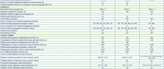
Main parameters of the multi-purpose turning and milling machine INTEGREX e-500H II
- The 37 kW milling head has a stroke in three axes (X - 870 mm, Y - 500 mm, Z - 1598 mm) and rotation along the B axis (240° (-30° +210°), indexing 0.0001°).
- 40 HP spindle The C axis (with a rotation resolution of 0.0001°) is activated using a plug-in worm gear.
- CNC-controlled automatic steady rest (optional)
- 5-axis machining
- Automatic tool changer with 80 or 120 positions (optional)
- Long boring bar system (max. length 1,000 mm) for 2 tools (optional)
Symbols, terms and explanations
Symbols for the configuration of turning machining centers:
- M - (Milling) driven tool;
- Y - controlled Y axis;
- S — (Spindle) counter spindle;
- T - (Tailstock) tailstock.
Explanation of terms
The spindle motor is an integrated spindle drive (ISM). The machine spindle is the axis of the drive motor. The CTX series (DMG) uses 9 standard sizes of motor spindles. The motor spindles have high precision and thermal stability due to liquid cooling. Motor spindles are used both in the main drive and in the counter spindle. (The CTX beta 800 machine is equipped with an ISM 76 - power (100% ED) 25 kW, torque (100% ED) 280 Nm. Rotation speed up to 5000 rpm, built-in C-axis (0.001°).
C-axis - in CNC lathes - software control of the spindle rotation angle and holding it. Used synchronously with the driven tool. The main parameter is the minimum spindle rotation angle (In the CTX series, the minimum controlled rotation angle is 0.001°). Can be built into the spindle motor or have a separate servo motor.
Y-Axis - The Y-axis expands the capabilities of live tools. Y-axis mechanisms allow you to guide the tool offset to the axis of rotation of the part. The main parameter is the maximum stroke
Counter spindle - in CNC lathes - an additional spindle (counter spindle) installed in place of the tailstock. If it is necessary to process a part from the opposite side, it is transferred from the main spindle to the counter spindle. To do this, upon command from the CNC, the rotation speed of the counter spindle is synchronized with the speed of the main spindle, the counter spindle moves, grabs and clamps the workpiece. Processing continues on the other side of the part.
Linear guides are rolling guides. To move the turret head along the X and Z axes, CTX series lathes use ball screws and ball (roller) linear guides, which have a low coefficient of friction (low heat generation), no “sticking” effect (high speed up to 30 m/min), Consistent precision (low wear) and very low lubrication requirements.
Linear drive – highly dynamic drive for maximum dynamics and long-term precision in the X-axis (upper turret). The drive with high speed strokes of up to 60 m/min and accelerations of up to 1.5 g reduces the auxiliary time to a minimum. The linear drive consists of linear guides and a linear motor, the ball screw assembly is excluded and the friction force approaches 0.
Direct Drive is a technology for driving a driven tool directly from an electric motor.
TRIFIX® is a three-point mounting method for mounting a tool onto a VDI turret with greater precision than conventional mounting.
A driven tool is a rotating tool (drill, cutter, tap) designed for installation in a turret.
VDI - (Verein Deutscher Ingenieure - Association of German Engineers) turret head with tool holders for CNC lathes (Tool holder fastening: a wedge with teeth on the shank of the holder), made according to the German standard DIN 69880 (VDI 3425) (GOST 24900-81). VDI connections are available in six sizes 16, 20, 25, 30, 40, 50 depending on machine power and tool size. Used for fastening both driven and non-driven tools.
BMT® - (Built-in Motor Turret) turret with built-in tool drive.
BOT - (Bolt-On Tools) turret with bolt-on non-drive tools. Haas documentation term.
TWIN is a machine with two independent working areas - two turret heads that work simultaneously with spindles. Patented concept from DMG.
Design
Unlike older analogues, modern machines with numerical control have a higher rigidity index and allow complex processing of parts to be completed in a shorter period. These advantages are due to design features:
- absence of gaps between subordinate elements;
- high level of strength of load-bearing elements, unit components and other components;
- minimum length of kinetic chains and number of mechanical gears;
- presence of feedback alarms;
- increased resistance to vibration loads arising during processing of parts;
- the presence of special systems designed to reduce the risk of thermal deformation.
Turning on machines is ensured thanks to guides. These components are subject to wear, but are resistant to friction. The structural elements are interconnected and operate in the same mode. This condition is associated with the high precision of products.
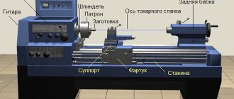
The basic design of a lathe consists of:
- beds;
- spindle or headstock;
- calipers;
- feed boxes;
- electrical part;
- turret heads.
The bed is the basis of the equipment on which the remaining components of the machine tool are placed. The headstock consists of two main elements of the unit: the gearbox and the spindle. The support includes a lower and upper carriage - elements that fix the working mechanism. The caliper receives movement through the feed box. The device operates using an electric motor. This component is similar for different models of lathes, and may differ only in power. Tool turrets are used to automatically change tools.
When working with large workpieces, machines can be used whose design includes special stands. They are used to fix the part at the desired height.
There are also turning centers on sale that add the functions of a milling machine to a lathe.
Russian manufacturers of turning and milling machines
JSC NIPTI "Mikron", Vladimir
Mikron NIPTI (Research Design and Technology Institute) was founded in 1957. Address: 600001, Russia, Vladimir, st. Dvoryanskaya, 27a bldg. 7, Website https://mikron33.ru/history.html
Currently, NIPTI Micron produces:
- TFC 1200-5 is a multi-purpose turning and milling center.
Southern Heavy Machine Tool Plant, LLC (YUZTS), Krasnodar
YuZTS Southern Heavy Machine Tool Plant, Krasnodar - was created in 2016 on the basis of the Krasnodar Machine Tool Plant named after Sedin (KZTS).
Currently, YuZTS produces:
- MF4M - Portal turning and milling center for processing large-sized parts of complex shape with various holes and grooves.
- VMM - Portal turning and milling center for processing large-sized parts of complex shapes with various holes and grooves.
- VC GANTRY MACHINE - Portal turning and milling center for processing large-sized parts of complex shapes with various holes and grooves.
- VCPR GANTRY MACHINE - Portal turning and milling center for processing large-sized parts of complex shapes with various holes and grooves.
Machine tool group STAN, Moscow
STAN - Machine Tool Group, Moscow - private company founded in 2012.
The companies of the Stan group produce turning and milling machines:
- STT 55F (1728F) – Turning and milling machining center
- STT 70F (1740F) – Turning and milling machining center
- STT 125F (1750F) – Turning and milling machining center
- STT 30 (1715) – Turning and milling machining center
- STT 55 (1728) – Turning and milling machining center
- STT 70 (1740) – Turning and milling machining center
Project "Machine Tool Building". FORT brand machines
FORT is a trademark of machine tools produced within the framework of the Machine Tool Building .
The project is being implemented by the partners of the “Machine Tool Building” project, which produce turning and milling machines:
- VNS – CNC lathe with horizontal bed
- VNS-1800 – CNC lathe with horizontal bed
- VNS-2200 – CNC lathe with horizontal bed
- VNS-2600 – CNC lathe with horizontal bed
- VNS-5000 – CNC lathe with horizontal bed
- VNS-6500 – CNC lathe with horizontal bed
- VNS-2800A – CNC lathe with horizontal bed
- VNS-3000 – CNC lathe with horizontal bed
- VNS-3500 – CNC lathe with horizontal bed
- VNS-4000 – CNC lathe with horizontal bed
- MT-52 – CNC lathe with inclined bed
- NT-500 – CNC lathe with inclined bed
- NT-700 – CNC lathe with inclined bed
- TS-35A – CNC lathe with inclined bed
- TS-35V – CNC lathe with inclined bed
- S-300TMU – CNC lathe with inclined bed
- T-42MSU - Lathe with counter spindle
- S-200TS — Lathe with counter spindle
- S-200TSM — Lathe with counter spindle
Ulyanovsk Machine Tool Plant, LLC (DMG MORI)
The world's largest Japanese-German machine tool concern DMG MORI has built an assembly plant in Ulyanovsk. The plant was launched (registered) on 06/04/2012
CNC lathes:
- CTX 310 ecoline – CNC lathe Ø 200 × 455 mm
- CTX 510 ecoline – CNC lathe Ø 465 × 1050 mm
- CTX alpha 500
– CNC lathe Ø 200 × 575 mm - CTX beta 800
– CNC lathe Ø 410 × 850 mm - CTX beta 800 TC
– turning and milling center Ø 500 × 750 mm - CTX gamma 2000
- CNC lathe Ø 700 × 2065 mm - CTX gamma 2000 TC
– CNC lathe Ø 700 × 2000 mm
Kovrov Electromechanical Plant Federal State Unitary Enterprise, KEMZ Kovrov
Kovrov Electromechanical Plant, KEMZ was founded in 1898 in the city of Trekhgorny, Vladimir region.
- KTS 3000 (Y, S) – Turning and milling machining center
- KTS 4000 (Y, S) – Turning and milling machining center
- KTS 5000 (Y, S) – Turning and milling machining center
- KTS 4000 TM - Turning and milling machining center with 2 turrets
- KTS TK 3108 – Turning and milling machining center with BMT tool blocks
- KTS TK 3110 – Turning and milling machining center with BMT tool blocks
StankoMashStroy, LLC Penza
Machine tool manufacturing company founded in 2006. Enterprise address: 440028, Penza, st. German Titova, 9A. Website: https://16k20.ru
The company produces universal screw-cutting lathes, CNC lathes and machining centers:
- ST25L — Turning machining center
- ST25LM – Turning machining center
Moscow Machine Tool Building
DMTG Moscow machine tool building was founded in 2022.
The company has established large-unit assembly of milling, drilling, and lathes. They make it possible to make parts for the automotive, aviation, military industries, as well as medical equipment. This is a new generation of technology in machine tool industry.
- CL - Turning center
- CL-15 – Turning center
- CL-20A – Turning center
- DL20M – Turning center
- DL25M – Turning center
- DL30M – Turning center
- DL32M – Turning center
- DL40M – Turning center
- DL-20MH – Turning center
- DL-25MH – Lathe center
- DL-30MH – Turning center
- DL-32MH – Turning center
- DL-40MH – Turning center
- CLD15 – Turning center
Machine tool plant Tulamash, LLC NPP
The Tulamash Machine Tool Plant was founded in 2013 and is a subsidiary of AK Tulamashzavod JSC, specializing in metalworking equipment. Website: https://cnc-tulamash.ru
NPP Machine Tool Plant Tulamash is engaged in the development and production of machine tools and critical machine components, including spindle units, guides of machine tools of the highest accuracy classes.
- 1TGK-4302 – CNC lathe
- 1TGK-4302 – CNC lathe
- 1TGK-4302+S – CNC lathe
- 1TGK-4302+Y – CNC lathe
- 6TVK-110 – Milling center
5-axis machine. Video.
- Lathe operator's manual. Next generation control system 96-RU8910. Revision M. February 2022. Haas Automation Inc.
Bibliography
Useful links on the topic
- Manufacturers of metal-cutting machines in the USSR and Russia
- Manufacturers of lathes in Russia
- Manufacturers of milling machines in Russia
- Manufacturers of grinding machines in Russia
- Manufacturers of turning centers
- Manufacturers of 5-axis centers in Russia
- Manufacturers of machining centers in Russia
- Manufacturers of drilling machines in Russia
- Manufacturers of forging and pressing equipment in Russia
- Directory of machine tool and KPO manufacturing plants
- Manufacturers of woodworking machines in Russia
- Manufacturers of household woodworking machines in Russia
- Manufacturers of chipping machines in Russia