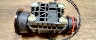
Electromagnetic valves for water are devices with which you can remotely shut off or open the flow of water, gas and any other medium located in the pipeline. These devices are called electromagnetic because they use an electromagnetic coil (solenoid) to operate. There are several types of such devices and each has its own characteristics and differences in operating principles.
An electromagnetic valve is a type of shut-off valve installed on various pipelines, including domestic ones
Purpose and application of solenoid valves
The solenoid valve is designed to control the flow of liquid and gaseous products at a distance. It can be shut-off or regulating. Control can be carried out either manually or using automation systems. In its design and purpose, an electromagnetic shutter is very similar to a regular one, with the difference that the locking element is driven not by muscular force, but by a solenoid, an electromagnet with a movable core. When voltage is applied to the solenoid inductor, it, depending on the polarity, pulls in or pushes out the core connected to the valve stem.
Such shut-off and control devices are used both in complex industrial installations and in home heating and water supply systems, and in household appliances. They are also used in vehicles running on liquid fuel.
Comparison of pneumatic actuated valves with solenoid valves
The main advantage of pneumatically driven valves over solenoid valves is their increased resistance to negative environmental factors and the medium passing through the valve. This is due to the fact that pneumatically operated valves:
- are actuated by compressed air rather than by fluid passing through the valve;
- do not have additional bypass holes, which are easily clogged with the slightest contaminants;
- less susceptible to environmental influences, since it is possible to move the distribution valve to the control cabinet, where it will be protected from harmful influences.
How can a system based on a pneumatically driven valve be more reliable than a system based on solenoid valves? After all, any valve with a pneumatic drive requires its own distributor, which increases the number of series-connected system elements. This should lead to a decrease in the overall reliability of the system. This remark is valid when operating valves under ideal conditions.
However, under unfavorable conditions, the stability margin of the solenoid valve may not be enough. This follows from the features of its design described above.
The next factor that speaks in favor of valves with pneumatic actuators is their lower hydraulic resistance and, as a result, greater flow of medium at the same inlet pressure.
This is achieved thanks to the angular (inclined) design of the valve. The flow passing through it deviates significantly less from straight-line motion, and therefore consumes less energy to overcome the valve resistance. As an example, Table 1 shows the Kv flow coefficient data for GEVAX series 1901R-KBN solenoid valves and VALMA series ASV pneumatic actuated valves. Table 1 - Comparison of flow coefficient Kv of valves of different designs
| Valve type | Solenoid valve | Pneumatic Actuated Valve |
| Fluid flow diagram | ||
| Valve size | Flow coefficient Kv, l/min | |
| DN 15 | 65 | 70 (+ 8%) |
| DN 20 | 110 | 150 (+ 36%) |
| DN 25 | 180 | 308 (+ 71%) |
| DN 32 | 250 | 608 (+ 143%) |
| DN 40 | 390 | 700 (+ 79%) |
| DN 50 | 575 | 910 (+ 58%) |
Unlike solenoid valves, pneumatically actuated valves are predominantly bidirectional, meaning they can flow in both the forward and reverse directions (see Figure 17). The direction shown in the image on the left is called “input under the disk”, in the image on the right - “input above the disk”.
Figure 17 – Allowable directions of fluid movement for valves with pneumatic actuators
Obviously, when the working medium is supplied “above the disk”, its pressure prevents the valve from opening. This effect leads to a decrease in the operating pressure of the valve, but to some extent it can be compensated by increasing the control air pressure.
An example of changes in operating pressure when supplying medium above and below the disk
Figure 18 shows the nameplate of the valve with pneumatic actuator VALMA ASV-T-040-AL063.
Figure 18 – Nameplate of valve with pneumatic actuator VALMA ASV-T-040-AL080-U
The operating pressure of the pneumatic valve when supplying the medium “under the disk” is 6 bar, when supplying the medium “above the disk” – 5 bar. These data are based on a control air pressure of 6 bar. However, by changing the control pressure it is possible to increase the operating pressure of the valve when supplying medium “above the disk”. This dependence is shown in Figure 19.
Figure 19 – Graph of the pressure of the working and control medium
The graph shows that increasing the control pressure to 8 bar allows you to increase the pressure of the working medium (at the inlet “above the disk”) to 10 bar, and increasing the control pressure to 9 bar allows you to increase the pressure of the working medium to 12 bar.
However, solenoid valves also have advantages over pneumatic actuated valves. Systems based on solenoid valves are generally simpler and less expensive than systems based on pneumatic actuated valves because they consist of fewer components.
Solenoid valves can be used in facilities that do not have a pneumatic system. Installing equipment for air compression and purification at such facilities leads to a significant increase in cost and complexity of the system as a whole.
Valve device
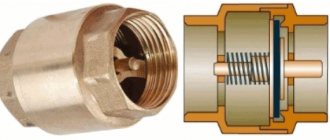
The composition of the main parts and assemblies of the solenoid valve largely coincides with a conventional manually operated device:
- Housing with inlet and outlet pipes.
- Working chamber with saddle.
- Disc, ball or petal locking element.
- Return spring.
- Rod connected to shut-off element and solenoid core
- Solenoid.
The magnetic valve body is made of metal non-magnetic alloys or durable plastics. The high tightness of the body allows the valve to be used in various environments, including active ones. Solenoid valves for water use rubber as sealing gaskets; for more active media, fluoroplastic is chosen. The solenoid must open and close the valve thousands or even tens of thousands of times during its service life, so the highest quality copper wires coated with insulating enamel are used for the windings.
The solenoid valve is controlled via wires; for their connection, contact groups are provided on the outside of the body.
The device must be resistant to external electromagnetic fields, noise and vibration.
There are other types of electromechanical drives, such as an electric motor with gearbox, pneumatic or hydraulic.
Direct acting valve operation
An electromagnetic valve, the diagram of which makes it possible to understand the principle of operation, can have direct action. This device does not have a pilot channel. In the central part there is an elastic membrane that has a metal ring. It is connected to the plunger through the spring. When a magnetic field is applied to the coil, the valve opens, the plunger rises and relieves the force on the membrane. The latter rises and helps open the valve. At the moment when closing occurs, there is no magnetic field, the plunger lowers and acts on the membrane.
For such a device, a minimum pressure drop is not required. The solenoid valve, a photo of which is presented in the article, can be used in pressure systems, as well as on drain tanks. The device can also be installed in storage receivers. Such a device can be installed in places where there is no pressure or is at a minimum level.
Operating principle of electromagnetic systems
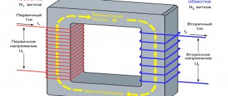
The operating principle of the electromagnetic shut-off valve is based on the physical phenomenon of electromagnetic induction. When current flows through an inductor, a magnetic field arises inside it, acting on a core of magnetic materials with a force applied in the longitudinal direction. This force, depending on the polarity of the applied voltage, tries to pull the core inside the coil or push it out. In this case, the shutter element opens or closes.
Solenoid valve coils can operate on either 5 to 36 volt DC or 220 V AC.
Devices with low control voltage have low power and limited force transmitted to the locking element. This allows the use of low-voltage semiconductor circuits to control them. Such devices are used in low pressure systems of the working medium, on pipelines of small diameters.
Drives operating on alternating current develop much greater forces and can be used on main pipelines of high pressure and large diameters.
Installation and connection
According to the type of location, gas valves are:
A remote gas gas solenoid valve is usually mounted in the engine compartment of a car, or placed directly on the gas reducer through an adapter. Built-in, located in the evaporator housing.
Sometimes, for greater safety, two valves are installed at once, after the multivalve (in the flow line before the evaporator) and on the gearbox.
The connection is made using gas equipment wiring, according to the diagram that is included in the gas equipment kit. When installing the 2nd generation, the harness is routed from the control button to the solenoid. During the 4th generation installation, the cable runs from the LPG control unit to the valve. There is no difference where to connect the terminals on the coil.
About the types of products
Products are classified according to several parameters.
Based on the position of the locking element in the absence of voltage on the coil, the following are distinguished:
- Normally open, or BUT. The passage for liquid or gas is open, but when voltage is applied, it closes.
- Normally closed, or NC. The passage for the medium is blocked, and when voltage is applied it opens.
Some models are produced as universal ones, and normally the position of the locking element is adjusted during installation and connection to the control network. Such switched devices are called bistable.
Depending on the working environment, shut-off valves are produced for:
- Air.
- Water.
- Pair.
- Active media
- Fuels and lubricants.
Devices for working in radioactive environments are distinguished by a special selection of materials with increased radiation resistance. The vacuum solenoid valve must provide particularly high tightness
Based on the characteristics of the external environment, the design of the device can be:
- Normal
- For wet areas.
- Heat resistant (for high temperatures).
- Frost-resistant (for extremely low temperatures).
- Explosion-proof. Such devices should not spark when turned on or off. For this purpose, they use special design solutions and materials.
According to the type of supply voltage, coils are divided into
- AC, high voltage. They develop high forces and are used on main pipelines of high pressure and large diameters.
- Direct current, low voltage. Used on pipes of small cross-section and low pressure.
There is a separate class of high pressure solenoid shut-off valves. They are called cutoffs. They are designed to instantly shut off pipelines or seal containers in the event of abnormal or emergency situations.
And finally, according to the type of functioning, valves are divided into
- One-way. This type of valve has only an inlet pipe. Usually they are normally closed and open the way for water or air flow to the external environment. Used as safety precautions.
- Two-way. The most common type has inlet and outlet pipes and is mounted in a pipeline break. They are used to control the flow in one of the circuits of the pipeline system.
- Three-way. They may have one inlet and two outlets, or two inlets and one outlet.
Three-way valves of the first type are used to redirect flows from one circuit to another (for example, in a heating system). This allows you to maintain the temperature of the working environment constant without changing the operating parameters of the heat source. Devices of the second type are used to mix two streams having different temperatures. A typical example is the single-lever ball mixer in the kitchen or bathroom.
You can get acquainted with all types of solenoid valves here.
Operating principle
The basis of its structure and further functioning can be disassembled from the instructions for their use attached to the models. Without taking into account the selected model of solenoid valve, whether it is a device with bistable control, normally open or normally closed, the operation of the device will look like this:
- Before the corresponding signal is sent to the coil, the valve will be in the closed position. The working medium will be locked using a rod equipped with a gasket.
- After the corresponding signal arrives at the coil, a force (electromagnetic) will arise in the solenoid itself, which will pull the plunger inside the coil, making some space above the membrane and between the rod free. The pressure indicator under the membrane will exceed the indicator inherent in the upper section, after which the passage will open and the liquid will flow through the valve body.
If the valve is open, the process will occur in the reverse order.
Area of use
The use of electromagnetic valves is carried out in a variety of areas of human activity, wherever there is a need to control the flow of liquids and gases remotely. This includes:
- Domestic heating systems.
- Water supply and water treatment systems.
- Technological installations.
- Pipeline transport.
- Heat generation and distribution.
- Appliances.
- Sewerage.
- Irrigation.
- Vehicles.
The use of solenoid valves in transportation is gradually declining as more types of vehicles switch to electric power sources and abandon liquid fuels and hydraulics, replacing them with more reliable electric drives. Similar prospects are visible in heating systems. But in water supply, sewerage and other industries, the role of electromagnetic gates will only increase.
Price overview
You can buy a solenoid air, deluge or gas valve with a power of up to 380 volts in Russia, Ukraine, Belarus at any specialized store. You will find devices of this type: freon, Honda, SVM, CEME, SKN for a variety of installations. Each manufacturer offers its own price list; we have collected average prices for valves produced in Russia, Italy, Germany and the CIS countries:
| City | Price, rubles |
| Almaty | 2300 |
| Voronezh | 2100 |
| Ekaterinburg | 2100 |
| Novosibirsk | 2200 |
| Moscow | 2400 |
| Kazan | 2300 |
| Samara | 2100 |
| Ufa | 2200 |
| Permian | 2100 |
All companies provide a one-year warranty on their products; sales are carried out in official dealer stores.
Advantages of solenoid valves for water
The main advantage of the device is the ability to remotely and quickly regulate the flow of the working environment. Without electromagnetic shutters, the operation of complex technological installations and simple household appliances, such as a coffee maker and washing machine, becomes impossible.
In addition, the electric drive allows:
- Connect the solenoid valve to a centralized and automated control system. This greatly increases the accuracy and efficiency of parameter adjustments compared to manual control.
- Reduce labor costs for managing technological processes.
- Increase production safety and eliminate the operator’s exposure to harmful factors in the production environment.
- Increase the efficiency of household appliances and production plants through precise and fast control of the flow of working media and their parameters.
An important advantage of a solenoid drive compared to an electric motor and gearbox is the absence of gears and worm gears, exceptional simplicity of the device and a minimum of moving parts.
This ensures high equipment reliability, minimal wear and a long service life.
The disadvantage of this type of device is the inability to smoothly adjust the degree of shutter opening. Only two positions are provided: “open” and “closed”.
Possible malfunctions and how to fix them
It is worth noting that high-quality installation and compliance with all operating rules specified by the manufacturer ensure reliable and long-term operation of the device.
But there are cases when the valve fails much earlier:
- Valve depressurization - most likely small mechanical particles have gotten inside the device. We recommend dismantling and disassembling the device, and then installing it together with an additional filter.
- The induction coil can fail if the voltage power is incorrectly supplied, or if the temperature or pressure inside the gas pipeline is exceeded. In addition, moisture may enter the coil, causing a short circuit. In all cases, it is recommended to dismantle the devices and replace the coil.
- Incomplete opening or closing of the valve may be due to contamination of the internal parts, a defective membrane, or voltage remaining on the solenoid.
In any case, repairs to the device can only be carried out by a qualified employee of a specialized organization with permission to work.
IMPORTANT!
The solenoid gas valve does not act as a gas tap, so a gas tap must be installed between the gas line and the valve. If you plan not to use gas for a long time, for example in winter, shut off the gas supply using the gas tap, not the valve.
DIY water solenoid valve installation
Before proceeding with installation, you must determine the type of connection. The most commonly used are:
- Threaded. The inlet and outlet pipes are equipped with external or internal threads; through the corresponding fittings, the fittings are built into the pipeline gap. The most convenient for self-installation, it is better to choose this type of connection.
- Flanged. The pipes are equipped with flanges; the ends of the pipes must also have flanges of the appropriate standard size; they are tightened together with bolts. They provide high pressure and flow intensity, often used on high and medium pressure lines.
Before installing the device, a number of preparatory operations should be performed. Pipes must be marked, cut to size and cleaned. The location for installing the electromagnetic device must provide free access to the device for its installation, maintenance and repair. Experienced professionals also formulated several recommendations:
- All work on installing or removing the device can only be carried out when disconnected from the network.
- The pipeline system must be supplemented with a mechanical cleaning filter. This will prevent contamination and damage to parts by foreign matter such as sand, rust flakes and lime deposits.
- The device body should not bear the weight of the pipeline section.
- The device should be connected in accordance with the arrows marked on the housing. They indicate the direction of flow.
- When installed outdoors, the valve should be protected from exposure to natural phenomena. A waterproof casing is usually sufficient. When working in low temperature conditions, the casing must be heated.
- Threaded connections must be sealed with FUM tape or plumbing thread.
- The cable for connecting to the control system should be copper. It must have a sufficient cross-section of at least 2 mm2.
The selection of a specific model is carried out based on calculations of the parameters of the pipeline system.
The pressure, pipe cross-section, required response speed and characteristics of the controlled medium should be taken into account.
Some tips for choosing the right device
There are several important parameters to consider when choosing a solenoid valve. One of the main indicators is the size of the inlet and outlet openings. The range of electromagnetic products is very wide. They may have distinctive design features. But, as a rule, this does not affect performance. One-inch solenoid devices, which have a flow rate of up to 40 l/min, are very popular.
The size of the valve outlet plays an important role; the throughput of the device depends on it
Important! Before purchasing a valve, it is recommended to pay attention to the mechanical regulator that is built into the device. It may have a different number of modes. The more there are, the more accurately the control in the system will be carried out.
If you need a valve with the highest possible throughput, you can purchase a device from the SVR series. The normally closed valve of this series has a fluid flow rate of up to 100 l/min. Prices for different valves differ and are determined by their quality characteristics.
Signs of a malfunctioning carburetor solenoid valve
The latest carburetors use a solenoid drive to control the fuel supply. How to check the solenoid valve for serviceability?
Its breakdown is determined by the following signs:
- The engine runs unsteadily at low speeds.
- The motor stalls when coasting.
- After turning off the engine, detonation of the working mixture is observed.
Indirect signs of a malfunction are also a decrease in speed when connecting powerful electricity consumers, such as a radio, low or high beam, heated windows.
How to choose
Before purchasing a specific valve option, it is recommended that you familiarize yourself with the technical characteristics. Some designs are capable of working at maximum efficiency in only one direction. If this aspect is not taken into account, then after a short period of time the device may fail, which implies additional material costs for repairs or the purchase of a new model.
The second aspect to consider when choosing is the environment in which you plan to use the solenoid valve. The technical specifications must indicate two diameters: internal and external.
Attention, some foreign manufacturers indicate information in inches. Most modern models can withstand pressure up to 10B. Analyzing the domestic market, the Danfoss device is in greatest demand
The manufacturer offers a whole line of valves:
Analyzing the domestic market, Danfoss devices are in greatest demand. The manufacturer offers a whole line of valves:
- If you need a model with flexibility and increased reliability, then EVR is the best choice. The line assumes direct exposure and is suitable for freezers or refrigerators.
- EVRA is relevant for operation in pipelines with hot gas.
- STF for climate control units capable of maintaining optimal temperatures at any time of the year.
Danfoss has gained wide popularity due to the high quality of its products.
Valve check
The carburetor valve should be checked in the following modes:
- Idling. After starting, increase the speed to 2100 and listen to the carburetor. A sharp characteristic sound should be heard indicating the shutter is closing. Next, smoothly reduce the speed to 1900; an opening click should be heard.
- Engine braking. You need to let off the gas without changing gear. In this case, a working valve will not work, even if the speed has dropped to 1900. If a click is heard, the device is faulty.
- After stopping the engine. If, when the ignition is turned off, spontaneous outbreaks of the detonating working mixture continue in the cylinders, the engine jerks and vibrates - this means that the valve does not shut off the fuel supply to the chambers and further to the cylinders.
- If you pull the solenoid valve power wire out of the connector while the engine is running, the engine should stall. If it continues to work, it means the valve is faulty.
In addition to ways to check the solenoid valve “on the go,” you can unscrew the valve from the carburetor body and try to apply voltage to it from the battery. One wire from the battery is connected to the contact block, the other to the body of the device. When voltage is applied, the valve should click and pull the needle inward. After the circuit opens, another click is heard and the return spring retracts the needle. At the same time, you can check whether the parts of the device are contaminated with resinous deposits. They need to be soaked in gasoline and removed with a soft cloth.
It is also necessary to check whether control voltage is supplied to the contacts. Its normal value is 10.5-14.4 volts. If there is voltage on the control unit, but not on the contact, it means the wire is faulty. It needs to be repaired or replaced.
If there is no voltage at the control unit connector, then most likely the unit itself is faulty. It is checked by connecting the valve to the battery with another temporary wire. A voltmeter or test light is connected to the terminal of the control unit that controls the valve. Next, you should start the engine. When the speed reaches 900 rpm, the light should flash, and at 2100 rpm it should go out. If you reduce the defense to 1900 rpm, it will flare up again. This behavior of the light bulb means the control unit is working properly. If the light does not light up or go out at all, and also turns on and off at different speeds, the control unit is subject to in-depth testing and, possibly, replacement.
Possible faults
Often, due to breakdowns of the gas electric valve, malfunctions occur in the operation of gas equipment. Such as:
- Unstable engine operation at idle;
- increased gas consumption/leakage;
- Gas system failure due to lack of pressure.
Causes of malfunctions due to which the unit does not hold and allows gas to pass through:
- clogged coarse filter;
- jamming/sticking of the core;
- wear (loss of properties, weakening) of the return spring;
- failure of the rubber seal or valve seat;
- coil malfunction.
In a carburetor circuit where gasoline electric power is present. valve, in addition to everything else, increased consumption/leakage of gasoline or failure of the engine to operate on standard fuel may be added. You can detect a leak by removing the gas hose from the carburetor with the car running or by purging the valve (in a closed state) with a pump/compressor.
Design features
The valve device consists of a polymer or metal body, inside of which there is a solenoid, plunger, rod and membrane.
The material for the body is plastic, or stainless steel, brass or cast iron, which is determined by the scope of use of the valve. For example, a metal casing is used in systems with chemically aggressive or high-temperature media, while plastic casings are used for simple tap drinking or industrial fresh water. Valve membranes and seals are made from polymeric materials based on rubber and polyethylene.
Description of the design of the standard device
The simplest solenoid valve has two ports: one inlet and one outlet. Additionally there may be three or more ports.
Photo - Solenoid valve design
Water or gas enters through the inlet (2). Any substance must pass through the tank opening (9) before entering the outlet (3). The outlet hole is closed by a piston (7).
The solenoid valve in the photo above is a normally closed solenoid valve of the ASCO, TORK or Danfoss type. It works as follows: these devices are connected to a spring (8), which presses on the piston against the opening of the flow area. The sealing material at the tip of the piston contains protection (gasket) against water or gas entering the holes while the piston is lifted by the electromagnetic field generated by the coil. The diagram demonstrates the operation of the standard one.
Photo - Solenoid valve
There are many variations in valve design. Conventional valves may have many ports and pistons. The two-way indirect-acting valve (return) has 2 ports - EV1140, DU50, DU32, DU100, DU15, DU25, RU16 series; if the valve is open, two ports are connected and fluid moves between them; if the valve is closed, the ports are insulated. If the valve is open, then the solenoid is not energized, then the valve is called normally open (NO). Similarly, if the valve is closed, then the solenoid is not energized, such a valve is called normally closed, say YCD21, YCPS31, YCWS1. There are also three-port and more complex device designs; their designation looks like 30 (3, 33, etc.). The three-way valve has 3 ports to control the electric actuator; it connects one port, or two of them (usually the intake port and the exhaust port).
A small solenoid valve can produce limited force. The approximate relationship between the required electromagnetic forces Fs, fluid pressure P and orifice area A for a direct acting valve is:
In some solenoid valves, electromagnetic forces act directly on the main valve. Others use small, complete solenoid valves known as piloted valves. Piloted valves require much less power, but are much slower. These solenoids typically require full power at all times to open fully and hold that position.

