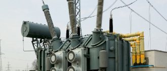
The most common electrical devices in industry and everyday life are transformers. Their purpose is to transfer power within an unmatched electrical circuit between its various circuits. They are used in cases where it is necessary to lower or increase the voltage between the energy source and the consumer. Transformers are also included in power supply circuits that convert alternating current into direct current. The operation of transformers is based on their ability to transmit electricity between circuits through magnetic induction.
Power transformers
Three-phase power transformer with cast insulation TSL (TSGL) and TSZL (TSZGL) 6, 10 kV
Three-phase power transformer TS and TSZ
Power transformers are electromagnetic devices designed to convert alternating current voltages while maintaining its frequency, as well as to transform the power supply system itself.
Design and arrangement of power transformers
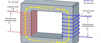
The main part of each power transformer is its core with several windings, made of ferromagnetic material. As a rule, these are thin sheets of special transformer iron with soft magnetic properties. The sheets are laid in such a way that the cross-sectional shape of the rods under the windings is close to a circle. To increase the efficiency of the device and reduce losses, entire sheets cover the joints between individual plates.
The transformer winding is usually made of copper wire with a rectangular or round cross-section. Each turn is isolated from the magnetic core itself, as well as from neighboring turns. For coolant circulation, technical voids are provided between the windings and its individual layers.
Each transformer has at least two windings: primary (electric current is supplied to it) and secondary (current is removed after converting its voltage).
Step-up transformer assembly
A feature of a step-up transformer is the larger cross-section of the cores of the primary winding of the transformer in relation to the secondary. A striking example is any unit that increases the supply voltage of 220 Volts to 400, 500, 1000 V, etc., accordingly, the insulation class of the transformer is selected according to the rating of the secondary winding, as in network transformers.
Please note that a large cross-sectional conductor cannot be wound with a homemade machine, since you will not be able to produce enough force. This is quite easy to determine - if the first turns move freely along the coil frame, or worse, you see a clear gap between the core and the frame, proceed to manual winding.
To assemble you will need to perform the following sequence of actions:
- Assemble the base from a dielectric material; to do this, you can cut it according to a cardboard pattern. The frame is assembled overlapping using glue.
Rice. 2: Make a frame for the transformer
If you have a ready-made sample, you can move on to the next step.
- Make holes in the cheek of the coil for the leads to the electrical network and to the consumer. Thread the conclusions through them.
Rice. 3: thread the primary winding lead - Place the first layer of insulation under the primary.
Rice. 4: Apply a layer of insulation to the coil - Wind the primary winding of the transformer - if thickness allows, use a machine, otherwise, do it by hand. When winding, every 4-5 turns, check the rigidity of the fixation and the tightness of the fit.
Rice. 5: wind the primary
If there are visible gaps, it is recommended to press down the coils with a wooden press die or nail them through the die with a hammer.
- Count the number of turns, it should correspond to the calculated one, insert the leads into the holes. Place a layer of insulation on the primary.
- After the insulation layer, wind the secondary, since a thinner wire will be used here; this procedure is easier to perform on the machine.
Rice. 6: wind the secondary winding
Periodically check the tightness of the turns and their fixation on the rod. A good fixation should not sag or deform when pressed with your fingers.
- If all the turns do not fit in one layer, they are laid out in several, then it is important to maintain the same number of turns in each of them. The layers are layered with dielectric material; note that the thickness of the insulation should not significantly affect the overall dimensions of the coils.
Rice. 7: Insulate the first layer - Bring the ends of the secondary winding to the cheek of the frame.
- Place the magnetic core in the window of the frame, the core is assembled alternately on each side, otherwise the losses will be too large. Then the core expands for tight fixation.
Rice. 8: Place the coils on the core
Powerful transformers with high voltage ratings are additionally impregnated with paraffin insulation. This procedure leads to increased capacitive losses, but creates additional protection against electric current.
Principle of operation
The operating principle of any power transformer is the phenomenon of electromagnetic induction. An alternating current is supplied to the primary winding, which forms an alternating magnetic flux in the magnetic circuit. This occurs due to its short circuit on the magnetic circuit and the formation of adhesion between the windings, inducing an EMF. A load connected to the secondary winding produces voltage and current in it.
Structurally, to obtain any voltage on the secondary winding, the required ratio of turns between the windings is used. The power transformer has the property of reversibility. In other words, it can be used to both increase and decrease voltage. In most cases, a power transformer is used to solve certain problems. For example, specifically increase or decrease the voltage. In a step-up transformer, the voltage on the primary winding is lower than on the secondary.
Step-down transformer assembly
A step-down transformer will have a large number of turns on the primary. In everyday life, they can often be found in power supplies, welding machines and other equipment. True, pulse units use a different technology, so repairs of such devices are carried out without transformers.
Since making a welding transformer with your own hands is quite important for homemade projects, let’s look at this option as an example. The requirements for the assembly process correspond to the previous one. A distinctive feature of such a unit is the large cross-section of the wire in the secondary winding, since the welding current can reach hundreds of amperes.
The manufacturing process is as follows:
- Use an old one or make a spool base.
- Fix the insulation layer on the transformer frame.
- Wind the primary winding with alternating layers of insulation.
- Insulate the primary and wind the secondary winding, since the large diameter of the wires will not allow you to do this manually, use a bench tool.
- Fix the terminals of both coils.
- Install the core plates.
Classification of power transformers
Depending on the voltage class and total power consumption, power transformers are conventionally divided into the following categories:
By power:
- Up to 100 kVA, up to 35 kV;
- 100 – 1000 kVA, up to 35 kV;
- 1000 – 6300 kVA, up to 35 kV;
- More than 6300kVA, up to 35kV;
- Up to 32,000 kVA, 35 – 110 kV;
- 32,000 – 80,000 kVA, up to 330 kV;
- 80,000 – 200,000 kVA, up to 330 kV;
- More than 200,000 kVA, more than 330 kV.
Multilayer cylindrical bobbin windings
Multilayer cylindrical coil windings (Figure 3) are wound from round wire and consist of multilayer disk coils located along the rod. Radial channels for cooling can be left between the coils (through each coil or through two or three coils). Such windings are used on the higher voltage side at Sst ≤ 335 kV×A, Ist ≤ 45 A and Ul.n ≤ 35 kV.
| Figure 4. Double-layer cylindrical winding | Figure 5. Helical winding |
Types of power transformers
Power transformers can be divided into several types based on the following characteristics and indicators:
- Cooling type. There are dry and oil transformers. The first option is air-cooled and is used where environmental and fire safety requirements are increased. The second option is a housing filled with oil with dielectric properties, into which a core with windings is immersed;
- Climatic design: external and internal options;
- Number of phases. There are three-phase (the most common) and single-phase;
- Number of windings. There are two-winding and multi-winding options;
- Purpose: increasing and decreasing.
An additional criterion is the presence or absence of an output voltage regulator.
Advantages and disadvantages of cores
- Stacked ones are more often used for constructing magnetic cores with an arbitrary cross-section, limited only by the width of the plates. Voltage transformation devices with a square cross-section have the best parameters. The disadvantage of this type of core is the need to tightly tighten the plates, the low fill factor of the coil space, as well as increased dissipation of the magnetic field of the device.
- Twisted cores are much easier to assemble than type-type ones. The entire W-type core consists of four parts, while the U-shaped type has only two parts in its design. The technical characteristics of such a transformer are much better than those of a type-setting transformer. The disadvantages include the need for a minimum gap between parts. With physical impact, the plates of the parts can peel off, and in the future it is very difficult to achieve a tight fit.
- Toroidal cores have the shape of a ring, which is made of transformer iron tape. Such cores have the best technical characteristics and almost complete elimination of magnetic field dissipation. The disadvantage is the difficulty of winding, especially wires with a large cross-section.
In W-type transformers, all windings are usually made on the central rod. In a U-shaped device, the secondary winding can be wound on one rod, and the primary winding on another. Especially often, there are design solutions when windings divided in half are wound on both rods, and then connected to each other in series. At the same time, the wire consumption for the transformer is significantly reduced and the technical characteristics of the device are improved.
Power transformer elements
The design of a power transformer implies the presence of the following elements:
- Power inputs are devices through which the load is supplied. Can be located inside the product or outside. The bushings are insulated with various special materials and differ in the type of insulation and design;
- Coolers. For powerful power transformers, an oil cooling system is provided. Cooling of the oil itself is carried out using radiators, a corrugated tank, forced ventilation, oil-water coolers or circulation pumps;
- Output voltage regulators are devices designed to change the transformation ratio. They can operate both under the influence of a certain load and without it (depending on the design). Essentially, regulators add or reduce the number of turns in the winding.
Power transformers can be equipped with additional attachments:
- Gas relay is a device with a protection function. If the transformer is unstable, the oil decomposes into its components, releasing gas. The gas relay either turns off the transformer or notifies with warning signals;
- Temperature indicators – sensors that measure oil temperature;
- Desiccant absorbers are devices that absorb condensation formed under the protective cover, thereby preventing it from entering the oil;
- Oil regeneration system;
- Automatic coolant pressure increase protection system;
- Oil level indicator.
Autotransformer
The windings of this device are one circuit and their interaction with each other is ensured by both electromagnetic and galvanic coupling. They allow different output voltages to be obtained at different terminals from a group of turns. Examples of transformers can be seen in Fig. 4. Saving wire on the winding and the amount of core material allows you to reduce the cost and weight of the device. The presence of a galvanic connection between the windings is its disadvantage. Autotransformers are used in automation systems and are widely used in high-voltage networks. Three-phase autotransformers have become widespread. Power autotransformers are used in starting systems for powerful electric motors and have a power of hundreds of megawatts. One type of autotransformer is a laboratory autotransformer (LATR), which allows you to arbitrarily change the output voltage within the regulation range. A contact motor with a carbon brush can be moved from turn to turn of the winding on a toroidal core using a rotary handle, which ensures a smooth change in the output voltage. The most commonly used LATRs are single-phase with an output voltage range of 0-250 volts and three-phase 0-450 volts.
Power transformer parameters
- Rated power. For a transformer with two windings, the parameter is equal to the power of each of them. For a three-winding version with different power windings, the parameter is equal to the larger of the indicators;
- The rated voltage of the windings is a characteristic parameter for no-load operation;
- Rated current is an indicator at which long-term operation of the device is permitted;
- Short circuit voltage is a characteristic of the impedance of the windings.
- Short circuit losses;
- No-load current – losses of magnetic core material (reactive and active);
- No-load current losses;
- Transformation coefficient.
Trial
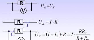
To check the performance of U-shaped or toroidal transformers at home, you can use a conventional multimeter. To do this, switch the measuring device to the ringing mode and check the integrity of each of the windings. Then check the insulation between each winding and the magnetic core and the resistance between both windings. This is the simplest set of tests, which will give a general idea of the serviceability of a home-made unit.
To check the absence of short-circuited turns, a lamp is used that is connected in series to the primary winding.
In addition, electric machines are tested in idle and short circuit conditions. Such checks show how well the converter is assembled, but it is not necessary to perform them at home.
How to choose a power transformer
The choice of power transformer for operation in enterprises is based on the selection of power, as well as in accordance with the requirements for power reliability. To ensure uninterrupted power supply, in some cases it is necessary to install several transformers. The power of each device is selected in such a way that if it fails, other devices are able to take over the functions of this missing link, taking into account possible overloads.
Another important criterion is the availability of protection:
- From internal damage. Provided with devices that monitor the presence of gases, temperature, pressure and oil cooler level;
- From overloads. The so-called differential protection is used when current transformers are installed on each phase.
Repair and maintenance
The reliability of power transformers directly depends on the quality and timeliness of their maintenance. Devices installed in premises where plant personnel work are subject to daily inspection with monitoring of oil level indicators, the condition of the absorber and regeneration devices. In addition, the integrity of the body and main elements is checked. Transformers in rooms without personnel are inspected once a month, and transformer points - twice a year.
An unscheduled inspection of a power transformer and its protection systems is carried out in case of a sharp change in ambient temperature, as well as in emergency conditions. Voltage regulation devices are also subject to periodic maintenance. The reason is the oxidation of contact groups, which leads to an increase in their contact resistance. Before seasonal load changes (usually twice a year), the device is disconnected from consumers and power, after which the voltage regulator is moved sequentially to all possible positions. The procedure helps to destroy the oxide film.
Laboratory oil analysis is performed every year during major repairs. If the oil does not meet the requirements during visual inspection (color) or according to inspection data, it is replaced or topped up.
Winding connection diagrams
The transformer group shown in the picture above consists of 3 single-phase transformers. However, this system is heavy, bulky, and also expensive.
The big minus is that the magnetic circuit is not symmetrical. The magnetic resistance of the middle coil is less than that of the outer coils.
You will also probably be interested in learning the disassembly procedure from our article - how to disassemble a power and oil transformer. And also what kind of testing must be carried out after eliminating defects - testing the power transformer after repair.
I hope the information was useful and informative!