This value of electric current is used to power most household appliances in the house. Often, they receive their charge from battery-powered devices.
But if they break, then a problem arises: how to get 12 Volts AC?
This is what we will try to analyze further, recalling the most common options.
Get a voltage of 12 Volts from 220
This is a fairly common change that can be made in several ways:
- Reduce tension without using a distributor.
- Use a 50 Hz distributor.
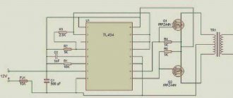
- Connect a pulse transformer that can be combined with a straight-line rectifier.
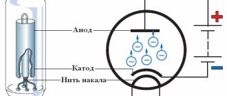
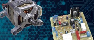
Operating principle of a pulse transformer
Since transformation concerns high-frequency currents, the design of pulsed devices is characterized by the small size of the magnetic core and a small number of transformer windings. This makes it possible to significantly reduce the size and weight of these devices compared to a conventional transformer. In this case, the output power of both devices will be the same.
A diode bridge and smoothing capacitors are used to rectify the voltage. The electric current passes through the transistor switch, which is in the open state, and then through the primary winding. At this moment, the magnetic circuit of the core is saturated and an EMF is created on the signal winding. The winding current charges the capacitor, which increases the voltage on the plates, which can turn off the transistor.
Gradually, the voltage on the signal winding decreases and disappears. As a result, the capacitor is discharged through it and the transistor is subsequently opened. This cycle is repeated constantly at a high frequency of tens of thousands of Hertz.
For conventional incandescent lamps, the voltage coming from the secondary winding can be connected directly. If you need to power electronic devices with a constant voltage of 12 volts, then rectifier diodes are used to convert it. Under the influence of the secondary winding current, an opposing magnetic flux is formed. In turn, it contributes to the growth of reactance in the primary winding and affects the signal winding. Due to this, the output voltage is stabilized.
If the thread burns out, a break occurs in the load circuit. This leads to an imbalance of magnetic fluxes and failures in pulse generation. Therefore, electronic transformers require a load connected to the output in order for them to function properly. The absence of such a load quickly disables the device. Therefore, when choosing the desired transformer model, you need to know the possible power range of the lamps that you want to connect. These data must correspond to the permissible values specified in the technical data sheet of the device.
HOW TO GET A REDUCTION WITHOUT USING A DISTRIBUTOR
This is only possible in three ways:
- Get a reduction using a damping element. Quite a popular method, used to recharge low-power devices. The disadvantages include a low power factor. However, it is often used in inexpensive devices.
- Limit the flow with a resistor. The option is not the best, but it is still used and is suitable for charging diodes. The main disadvantage is the large heat generation on the resistor.
- Use an automatic distribution transformer or a similarly wound coil.
What is a step-down transformer?
So, a transformer is an electrical device that transforms electrical energy, namely, changing voltage. If the output, that is, changed, voltage is less than the input, the transformer is called a step-down transformer. If, on the contrary, as a result of the conversion the voltage increases, then the transformer is called a step-up transformer.
Step-down transformer 220/12
Why do you need a step-down transformer in everyday life? Low-voltage electricity powers laptops and mobile phones, but they are always sold together with transformers, commonly referred to as “power supplies.” Low-voltage lighting, which uses halogen or cutting-edge LED lamps, is a different matter.
Today, many people want to get one because of a number of advantages:
- there is no danger of electric shock or fire (it is especially advisable to equip bathrooms and other rooms with high humidity with such lighting);
- compared to traditional ones, low-voltage lamps are much more economical: for example, LEDs with the same luminosity consume 15 times less energy than a 220 V incandescent lamp;
- Low-voltage lamps last much longer than their 220 V counterparts: LED manufacturers promise 50 thousand hours of operation and even provide a 3-year warranty.
To connect such a lighting system, a transformer must be purchased separately. But in its simplest form, you can do it yourself.
SILENCER HEAT RECEIVER
Before we look at this topic, let's talk about the rules that need to be followed:
- The power supply unit is designed to work with only one device.
- Each of the external elements must be covered with insulation. Do not touch the electronic circuitry of the unit unless there is a load connected to it or a stabilizer is not connected to it to reduce the DC current.
This sequence cannot cause death, but the unpleasant effects of electricity are guaranteed.
The value of the reducing cooler is determined by the equation:
C (microfarad) = 3200 x I (load) / root of (U input sq. - U output sq.) or C (uF) = 3200 x I (load) / root of U input
It is useless to obtain in other ways, due to the reduction in intensity from 220 to 12 V by a resistor, a lot of heat is generated, and it does not make sense to wind the inductor to obtain the required Volts, because it is very expensive and difficult to implement.
Purpose and principle of operation
What is a voltage converter. This is the name given to an electronic device that changes the magnitude of the input signal. It can be used as a device to increase or decrease its value. The input voltage after conversion can change both its magnitude and frequency. Such devices that change DC voltage (convert it) into an AC output signal are called inverters.
Voltage converters are used both as a stand-alone device that supplies consumers with alternating current energy, and can be included in other products: uninterruptible power supply systems and supplies, devices for increasing direct voltage to the required value.
Inverters are harmonic voltage generators. Using a special control circuit, a DC source is created to periodically switch polarity. As a result, an alternating voltage signal is generated at the output contacts of the device to which the load is connected. Its magnitude (amplitude) and frequency are determined by the elements of the converter circuit.
The control device (controller) sets the source switching frequency and the shape of the output signal, and its amplitude is determined by the elements of the output stage of the circuit. They are designed for the maximum power consumed by the load on the AC circuit.
The controller is also used to regulate the magnitude of the output signal, which is achieved by controlling the duration of the pulses (increasing or decreasing their width). Information about changes in the value of the output signal at the load enters the controller via a feedback circuit, on the basis of which a control signal is generated in it to save the necessary parameters. This technique is called PWM (pulse width modulation) of signals.
In the circuits of power output switches of a 12V voltage converter, powerful composite bipolar transistors, semiconductor thyristors, and field-effect transistors can be used. Controller circuits are implemented on microcircuits, which are ready-to-use devices with the necessary functions (microcontrollers), specially designed for such converters.
The control circuit ensures the sequence of operation of the keys to provide at the inverter output the signal necessary for the normal operation of consumer devices. In addition, the control circuit must ensure symmetry of the half-waves of the output voltage
This is especially important for circuits that use step-up pulse transformers at the output. For them, the appearance of a constant voltage component, which can appear when symmetry is broken, is unacceptable
There are many options for constructing voltage inverter (IN) circuits, but there are 3 main ones:
- IN transformerless bridge;
- transformer IN with neutral wire;
- bridge circuit with transformer.
Each of them finds application in its own area, depending on the power source used in it and the required output power to power consumers. Each of them must have protection and alarm elements.
Protection against undervoltage and overvoltage of the DC source determines the operating range of the inverters “at the input”. Protection against high and low output alternating voltage is necessary for the normal operation of consumer equipment. The operating range is set according to the requirements of the load used. These types of protection are reversible, that is, when the equipment parameters are restored to normal, operation can be restored.
When protection is triggered due to a short circuit in the load or an excessive increase in output current, a thorough analysis of the causes of this event is necessary before continuing to operate the equipment.
The 12V converter is the most suitable for creating a local power network. The availability of a large number of vehicles and 12V DC batteries allows them to be used to meet user demands. Such networks can be created in a variety of places, starting from your own car. They are mobile and do not depend on the parking location.
SUPPLY BOX ON MAINS DISTRIBUTOR
Standard and widely used sequence, used for music amplifiers and radio tape recorders. But only if you connect a good filter cooler that can make the necessary pulsation.
Plus, connect a 12 Volt stabilizing element. In its absence, the intensity will change due to current surges in the network: U output=U input* by coefficient. Transform.
Remember, the output voltage can be obtained 2-3 values higher than the output voltage of the BP-12 V, but not higher than thirty, it is determined by the capabilities of the stabilizer and its strength balances between the incoming and outgoing force.
The distributor's ability to receive 12-15 volts of varying flow. The forward tension will be slightly higher, about 1.41 times. It will approach a sine wave at the input voltage.
Calculation of parameters
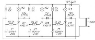
To prevent breakdown of parts of transformerless circuits, they must be correctly calculated. Each device has its own method.
The transistor unit is calculated according to Ohm's law: U=I×R. It is necessary to calculate the resistances R1, R2, R3 based on the value, voltage and current that each zener diode can withstand.
R=U max/I min.
Calculation of the ballast capacitor for blocks with an RC circuit is carried out using the following formula C = I eff/2*3.14*f *√(Up²-Uв²), where:
- C - ballast capacity (farad);
- Up and Uв — supply and output voltages (volts);
- I eff—load current;
- f is the signal frequency at the device input (hertz).
Since 1 farad = 1 million microfarads, the formula can be simplified:
C = 3200*I eff/√(Uп²-Uв²).
Resistance R1 (kOhm) is approximately equal to 0.025 of the value of the ballast capacitor. Its power should not be lower than 1 W (optimally 2-5 W).
If manual calculation is inconvenient, find and use an online calculator.
OPTIONS TO GET A FLOW REDUCTION FROM 24 TO 12 VOLTS, OR A STABLE VOLTAGE
To obtain a stable flow from twenty-four to twelve values, it is recommended to use a linear or pulsating stabilizing element.
The need for this appears in order to get power from a bus or truck, its power is 24 Volts.
In addition, you will acquire an already stable intensity that tends to change. Even in motorcycle wiring it rises to 14.7 V.
Therefore, this sequence can be used to recharge diode strips and light points on a car.
It is allowed to connect a load from 1 to 1.5 A. In order to increase the flow, a pass-through receiver is added, but after that the incoming voltage may drop by 0.5 V.
You can also use LDO-stabilizing elements; they are linear, but have a slight reduction in force.
For example, pulsating: AMSR-7812Z, AMSR1-7812NZ. Their connection is similar to L7812. The same methods are used to reduce the flow intensity from the laptop's power supply.
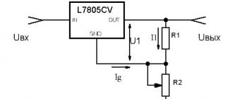
It is best to use pulsed current-reducing voltage converters, for example the LM2596 IC. The electronic circuit shows the input and output (In, Out).
In stores there is an option with a stable output voltage, as well as with a controlled one.
Let's sum it up
Before purchasing a step-down transformer for your home, it is important to calculate all the parameters. You should not treat this carelessly, because the durability of the converter depends on the correctness of the calculations. If you decide to make such a device yourself, then you need to be even more careful about the calculations. Unless, of course, the home master expects to use a ready-made converter.
We hope that our dear reader has found the information he needs in today’s article. If you have any questions on the topic, ask them in the discussions below. The editors of Seti.guru will be happy to answer them. And perhaps someone has experience in making step-down transformers (whether successful or not). In this case, please share it with novice home craftsmen. And finally, we suggest you watch a short but very informative video on today’s topic.
INCREASE FIVE VOLTS TO TWELVE
This can be done using lithium batteries with a current of 3.7-4.2 V.
If he talks about power blocks, if you have certain knowledge, you can intervene in the internal circuit.
Or make it much easier and achieve 12 V by connecting a boost converter. In the store you can purchase models with stable (12 V) or adjustable voltage (from 3.2 to 30 V) at an output of 3 A.
This converting element is sold on a ready-made electronic circuit, which has input and output marks.
An additional way is to take the MT 3608 LM 2977, the ability to raise the current to 24 V and transfers the output voltage to 2 A. In the picture below, the input and output locations are clearly visible.
Suitability of the power supply at home
Everyone in their home has various equipment that runs on batteries or accumulators. In order not to change the elements every time, it is powered from any source connected to a 220 V network.
You should not expect much power from a completely transformerless small-sized unit. Cordless tools (screwdrivers, drills, circular saws), pumps, tablets and laptops will not work on it.
Lighting devices and electronic equipment that consume current up to 500 mA can be connected to such a power supply:
- small-sized receivers;
- LED lamps and garlands (but not ribbons);
- portable low-power medical equipment (wrist blood pressure monitor, pulse meter and other parameters);
- phone charging modules;
- Kids toys;
- tape recorder motors, fans;
- homemade devices;
- Arduino boards.
How to make a 220 to 12V transformer with your own hands
To make your own step-down transformer, you will need the following materials:
- a core that can be taken from an old TV;
- varnished fabrics;
- thick cardboard;
- boards and wooden blocks;
- steel rod;
- glue and saw.
First, let's look at the option of making a simple machine for winding wire.
| Illustration | Action to be performed |
| This is the simplest device for winding wire onto a reel. The diagram clearly shows how it can be assembled. However, there are more convenient devices that will speed up the process. | |
| Using an ordinary vice, a steel rod and a brace (hand drill), you can assemble a winding device that will save effort and time. | |
| Another device you can’t do without. Often old coils are used to make a transformer. It is this machine, together with one of the previous devices, that will allow you to carefully rewind the wire from one reel to another. |
Now we should consider making a cardboard frame onto which the wire will be wound directly.
| Illustration | Action to be performed |
| The dimensions of the frame are measured according to the core (it should fit inside quite tightly). Based on the fact that the core can be either made of ordinary plates or with a perforation, we invite the reader to familiarize themselves with both options. | |
| We make a pattern according to the dimensions, which is glued together. For fixation, you can use any glue, but it is better to give preference to waterproof one. The best option would be epoxy. | |
| And here you can see the size ratio of the prefabricated frame, which is more difficult to manufacture, but more reliable and does not require gluing. Remember that failure to comply with the parameters may lead to unstable operation of the transformer. |
When everything you need is ready, you can start winding. This work also has its own nuances that should be taken into account.
Illustration Action to be performed The wire should be unwound from the “donor” coil from the top, and wound, on the contrary, from the bottom up. The distance between the coils should not be less than a meter. The wire is held with the right hand, and rotation is performed with the left. Terminals for various voltage values are sealed using insulating gaskets. They can be made from wound wire or soldered a flexible lead to it, which is more convenient. The place of adhesion must be isolated. The lead is passed through a hole in the cheek and fixed. In order not to get confused later (if there are several terminals), it is better to mark it immediately. The fixing insulating pads are glued, however, even in this case, additional fixation is necessary. The figure shows how the fixing insulating pads are clamped with a wound wire
It is important to do everything according to the instructions - only in this case can you hope for a positive result. Remember that the turns of the wire must fit tightly to each other - this will ensure a stable magnetic field of the coil
Calculation of the number of turns of the primary and secondary windings
The main work in the manufacture of a transformer can be called calculating the number of turns of the primary and secondary windings. On average, for a converter of 90−150 W, the number of turns per 1 V equal to 50 Hz / 10 = 5 is taken into account. The total number is calculated using the formulas:
- W1 = 220 × 5 = 1100;
- W2 = 12 × 5 = 60.
We get the required number of turns of the primary winding - 1100, and the secondary - 60.