Anton Sviridov
647 0 0
Anton Sviridov March 7, 2019
Seamster from instructables.com shared his experience making a wood lathe table with drawers. Further from his words.
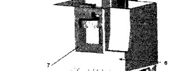
I had a lathe, but there was no permanent place for it in the workshop. So I decided to make a homemade table from an old door. The design included three simple drawers for tools.
Assembling the underframe
The legs were laminated from several individual boards to add strength and support the bottom shelf. Photos show assembly details.
The base is assembled using glue as well as screws installed in pre-drilled holes.
Stand for the machine (strong materials, fuck it.)
Stand for the machine (strong materials, fuck it.)
Message #1 Vladimir52 » May 24, 2022, 6:24 pm
Good afternoon! There is a task that is probably the most trivial for any student of Mechanics and Mathematics, but beyond my strength. I would like to make a stand/stand/table for a lathe, with sufficient rigidity (that’s another question), and minimal weight and price. Quite an optimization task for modeling, which, unfortunately, I have not mastered yet.
I really liked Danil’s project, which has one drawback for me - it’s too heavy, about 100 kg.
Therefore, I imagined myself as a designer, and began to wonder, what if I made the same thing, but from an aluminum profile? This will give me a weight gain of about 2.5 times. Although, in his specific project, I would add a couple of diagonal ribs and close the profile that goes under the frame into a pipe. I figured it out, did the math, and it turned out to be about 300 euros just for the profile material. You also need to cook it and make a stainless steel bath.
It is clear that Danil’s project pulls a “slightly” heavier machine (mine is only 130 kg versus Danila’s 260 kg, and the torque on the spindle is 30 percent less, and in general, no one accurately calculated the rigidity of this design), and it is possible reduce the footage, but this does not change the picture much. In addition, according to estimates, I need the main profile to be 40x40x3 mm, and for the frame 80x40x3 mm - these are quite massive pipes, and the weight advantage may come to naught, i.e. the table will stupidly turn out to be just as heavy. But I need to be able to evacuate him in one go.
And here the question arises, is it because there are no aluminum cabinets/tables that a profile made of thin steel and equal in rigidity to an aluminum profile will turn out to be the same in weight? Maybe I should just take a thinner (and much cheaper) steel profile and design a table for it? What do you think? Thank you.
What parts do metal lathes consist of, description and purpose of each piece of equipment. Necessary processing parameters.
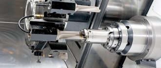
The design of the most modern lathe, despite its centuries-long history of development, is still not very different from its ancestors. Almost all fixtures are still based on the principle of rotating the workpiece, clamped into a chuck on one side and a tailstock on the other. This arrangement is used for both woodworking machines and metal processing equipment. At the same time, a metal lathe, despite the complexity of the design, is quite possible to assemble in a garage, because, as practice shows, nothing is impossible.
I make boxes
The boxes were constructed from scraps of plywood that were glued and twisted together. The bottoms of the drawers were made from scrap MDF which was also glued and screwed into place.
For the drawer slides, I cut strips of hardwood that were glued and screwed to the top long edges of each drawer.
What does a metal lathe consist of?
The theory of machines and equipment includes several types of devices for metal processing, which can be called a lathe. The simplest is the turning-screw-cutting type of device, which is based on the principle of rotation of the workpiece around its axis in a horizontal plane. The processing of a part is carried out with a cutter or other device, the working part of which is capable of moving both along the part and perpendicular to the axis of rotation. The device of a metal lathe itself has a number of elements that have a special name; these names are identical for all equipment designs.
Main nodes
The design includes two types of components: those without which work is impossible are called basic, those that can be omitted during creation or that can be made in the form of additional equipment are usually called non-basic.
bed
The bed is the most massive part of the machine. It acts as a supporting frame; all equipment is attached to it. This must be a massive and durable structure; the weight of the frame can reach 70% of the weight of the machine. At the same time, all elements of the frame body must be adjusted to each other as accurately as possible and have a rigid fixation. The large mass helps reduce vibration during operation, and the accuracy makes it possible to improve the quality of part processing.
Lathe support
One of the most important and complex nodes. In industrial models, the caliper has several adjustments, allowing you to move the tool holder both along the axis of rotation of the part and perpendicular to it. The cutter feed can also have a vertical direction. For a lathe made by hand, this unit is usually designed simplified - the cutter moves on the slide only horizontally, across the axis of rotation of the part. Raising and lowering is carried out with subsequent fixation when the engine is turned off. And movement along the axis is usually carried out along a threaded rod installed along the frame.
Read also: What is tahini halva made from?
At the same time, for many craftsmen, a simplified design is found only in the first assembled model; in the future, the caliper is constantly modernized and improved. But the main task of this unit remains reliable fixation of the cutting tool and its smooth feeding during operation.
Headstock and tailstock
In order to impart rotational movement to the part, a headstock is used. This is a complex design that includes a part fixation unit, a shaft on which this unit is attached, and a gearbox for changing the rotation speed. In industrial machines, the gearbox not only serves the rotating chuck with the clamped part; it also has a drive for feeding the support. In mini machines made by hand, the headstock is a shaft with a chuck for fixing the part, on one side, and on the other, a pulley for a belt drive is mounted on it. This entire structure is mounted on a pair of bearings and securely fixed to the frame.
The tailstock is a movable unit into which a fixed conical center is attached to support the part in weight. The important point is that the center of the tailstock and headstock are at the same level in both the horizontal and vertical planes. These coaxially located parts make it possible, on the one hand, to ensure rotation of the part around one axis, and on the other, to ensure the performance of other technological operations of turning work, for example, drilling holes or cutting internal threads.
Gearbox
In homemade metal cutting machines, the gearbox is often designed as a separate unit. The main task of the gearbox is to ensure rotation of the machine spindle at a given speed in the desired direction. The gearbox, as mentioned earlier, can also have a drive on the caliper; this option is especially important when cutting threads and obtaining the highest quality machined surface. Structurally, the box can be made:
- In the form of several gears on shafts;
- In the form of pulleys of different diameters, to which movement is transmitted using a belt drive.
For mini machines, the simplest solution is to use a two-speed electric drill as a drive - here both the engine and gearbox are combined in one housing.
Spindle
The spindle is designed to securely hold the workpiece being processed. In such a lathe this role can be performed by:
- Industrial lathe chuck;
- Faceplate;
- Collet;
- Chuck from an electric drill;
- Other types of clamping devices.
Other structural elements
The list of components and elements designed to ensure the operation of a homemade metal lathe may have many items, but the most important ones will be:
- Sled;
- Pinol;
- Tool holder;
- Apron.
Sled
The slide is designed for smooth movement of the tool holder. For homemade mini machines, only transverse slides are usually used, along which, when the flywheel rotates, the tool holder moves smoothly perpendicular to the axis of rotation of the spindle. Longitudinal movement is carried out using a caliper. This solution does not make it possible to perform a large number of operations, so when designing a machine it is worthwhile to also provide transverse ones for more precise work. Well, for machines that claim high results, devices for moving the cutter at an angle of 45 degrees to the axis of rotation will not hurt.
Pinol
Used to secure the workpiece in the tailstock. This part must have high strength and reliability, since it experiences constant friction against the metal of the workpiece.
Tool holder
The purpose of the tool holder is to fix the cutting tool on the caliper slide. During operation, other types of tools can be fixed into this unit, for example, knurling and cutters. The tool holder must provide, on the one hand, reliable fastening of the cutter, and on the other, prompt change in the position of the tool relative to the surface being processed.
Apron
The purpose of this structural element is to collect metal shavings. It is located under the bed and when processing metal, the shavings fall onto the apron and not onto the floor.
Electrical equipment of the machine
The electrical equipment of a screw-cutting lathe includes the main equipment - an electric motor with starting capacitors and a protection unit. And auxiliary electrical equipment - a lighting lamp and other elements, for example, an exhaust fan.
Particular attention in electrical equipment should be paid to devices for protection against electric shock. Here, first of all, it is necessary to install a protection relay, make a protective grounding connection and provide the control panel with a special large button to turn off the power supply. The presence of these protective devices as part of electrical equipment is an important requirement of safety regulations when working with such traumatic equipment.
Adapter for electric motor shaft from a bolt
Many summer residents and owners of private houses were faced with the need to process and saw boards, plywood and other lumber.
For such work you will need a circular saw, which will not be difficult to do using available tools.
Such homemade equipment will not be inferior to purchased equipment in functionality and quality of execution, allowing you to save several tens of thousands of rubles on the purchase of ready-made units.
Description of equipment
DIY circular saws can be stationary or portable.
The design of the simplest circular saw will include a metal or wooden supporting frame, inside of which are mounted an electric motor, an electricity supply control unit, a table top and the working saw itself, which is mounted on the circular saw shaft or installed through gears and a trunnion mechanism. The saw is located in a slot in the tabletop, which makes it easy to cut lumber, performing high-quality wood processing.
The table top can be made from lumber or you can use ready-made metal blanks for this.
Smooth easel tables are made from wood; such a table top will need to be covered with a durable metal sheet .
Otherwise, without metal protection, the wood will begin to wear out quickly, and the equipment will last several years during active use, after which complex and expensive repairs will be required.
First of all, you need to decide on the main tasks of the sawing machine. If you need to cut boards or firewood for the winter, then a simple installation of a sturdy table with a slot for a disk will be sufficient.
Some models imply the presence of an additional shaft to which knives, a jointer and a plane are attached.
Such universal machines are equipped with powerful electric motors, which allows you to perform a wide range of wood processing work.
When manufacturing a multifunctional machine, it is necessary to be guided by high-quality diagrams and drawings that will allow you to create universal and reliable equipment.
If you need to perform various types of carpentry work, then set up a coordinate table with guides. The existing stops and guides can be fixed at different angles, which allows not only to ensure safe operation of the machine, but also to perform high-quality wood processing, easily changing blades to saws of different diameters.
Advantages of homemade equipment
Homemade circulars are very popular due to their ease of manufacture, durability and reliability. Today, many summer residents use homemade units rather than buying expensive equipment in specialized stores.
The main advantages of this technique include the following:
- The versatility of the tool.
- Ease of manufacture.
- Possibility of significant savings.
- Reliability and durability of equipment.
The designs of stationary and mobile circular saws available on the Internet and in thematic printed publications make it possible to produce equipment for processing both thin workpieces and thick lumber. You can choose the simplest options that do an excellent job of processing lining, thin slats and plywood.
Characteristics and power
The functionality of using the equipment will depend on the correct choice of parameters, including speed indicators and drive power.
The power rating is affected by the maximum permissible diameter of the toothed saw. It is believed that to process lumber with a thickness of about 10 millimeters, an electric motor with a power of 1 kW will be required.
Based on the thickness of the processed and sawn timber, you should select the power of the electric motor.
Transmission from the drive in a self-made circular machine is best done using a V-belt. This allows you to ensure the necessary safety of using the equipment. When foreign objects get under the saw, the V-belt drive will slip on the pulleys, which eliminates injuries and jamming of the working disk.
Making a circular saw
Before proceeding directly to the manufacture of a circular machine, it is necessary to think through its structure and design, and ideally, select a drawing diagram according to which all work will be carried out in the future.
When planning the manufacture of the frame, it is necessary to remember that such a design must be stable and reliable . For industrial powerful saws, the base is made of reinforced welded metal structure.
For household models, you can use wooden blocks with plywood for the frame or weld a base from a metal corner.
The choice of electric motor used will depend on what kind of work and what kind of wood is planned to be processed on the machine. The drive can operate from a single-phase electrical network, or powerful industrial motors are used that operate from a three-phase electrical network.
You can make a powerful and easy-to-use circular saw from a washing machine motor. This won't be too difficult. Such motors are compact in size, operate on a single-phase network with a voltage of 220 volts, are reliable and are capable of operating at high speeds.
How to make a circular, maintaining a balance between economy, functionality and safety
Let's look at the main components that make up a home circular saw. You can make them yourself, but only if you have certain skills and tools.
Stand for circular saw
The frame can be made from a metal angle (channel) purchased from scrap metal collectors. If you have the means, contact a metal warehouse. Legs can be made from old water pipes, connecting them with corners.
A good option for a homemade frame made of rolled metal
IMPORTANT! The use of bolted connections is prohibited, since vibration will cause the fastening to come loose.
Electric welding must be used. Be sure to reinforce the corner joints with a jib. The upper part of the frame (on which the table will rest) and the podium for the electric motor are made from a corner with a side of at least 50 mm.
If the machine is equipped with wheels for movement, they must have steel rims and have locks. The higher the weight of the frame, the more stable the machine will be, and the safer the work will be.
What to make a table for a circular saw from?
The working surface is made of steel, duralumin or silumin sheet. It is permissible to use textolite, plexiglass or moisture-resistant plywood. Galvanized sheet metal is placed on top of the plywood.
The main condition is that the material should not crack from vibrations , have a smooth surface and not allow deflections under a weight of at least 50 kg. If the tabletop cracks or warps, the circular disk will jam.
Universal homemade table for a circular saw and router. I recommend watching this video
This will lead to injury and damage to the workpiece. The use of popular materials OSB and chipboard is undesirable. These materials are unstable to vibrations and can collapse at the most crucial moment.
There are two options for making a working groove for a circular disk:
- You can cut a groove.
- or place two halves of the tabletop at a distance from each other.
Popular: Self-sharpening circular saws is a task that is quite feasible for a home craftsman.
The disk should protrude above the table by no more than 1/3 of its diameter.
For any work, from sawing wood to carpentry, a reliable side stop is needed. This can be a metal corner or a block of hard wood. To adjust the working gap, you can provide parallel grooves on the tabletop or simply attach the stop using clamps.
The side stop must be parallel to the plane of the disc. The slightest deviation will cause it to jam.
Which motor to choose for a circular saw?
It is impossible to install the electric motor “by eye”. It is necessary to calculate the power. For a disk with a diameter of 350 mm, a 1 kW motor is required; for a disk with a diameter of 170 mm, 500 W is enough.
A good option is a motor from an old washing machine.
Washing machine motor
It is designed for long-term operation with medium load. If you plan to work with a disc larger than 350 mm, you can use a power unit from used industrial ventilation.
Large electric motors are usually installed on dampers (shock absorbers), which prevent unnecessary vibrations.
Examples of drawings with a brief description
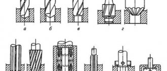
High-quality and durable shafts are made on a lathe from high-quality structural steel.
Below is an assembly drawing of a shaft for a closed type circular saw. Its technical features allow the shaft to be used on circular saws of both household and professional classes.
In addition, using a lathe and milling machine, you can independently make a shaft with jointing knives, the assembly drawing of which is shown in the image below.
Safety precautions
Before starting work you need:
- Make sure that the workpiece is installed correctly and that the cutter is securely fixed;
- Check that all tools and foreign objects have been removed;
- Wear safety glasses and lower the protective glass.
During operation:
- Do not touch rotating parts;
- Take off your glasses and remove the protective glass;
- Stop the spindle by hand.
After completing the work, it is necessary to turn off the power to the machine and additional equipment.