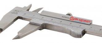
When performing most construction and repair work, you almost always need a pry bar, also known as a mini-crowbar.
This tool is used both in everyday life, in the garage, and on construction sites, because it is, in fact, a universal, strong and reliable lever.
Unlike a full-fledged bulky crowbar, its smaller copy is both lighter and more convenient.
A crowbar, as a mini-crowbar is often popularly called, can have an intricate shape, from which several types of this product are distinguished.
And each of them copes with a specific job more effectively than others.
Purpose of pry bars
This tool functions as a strong lever and at the same time a percussion instrument.
With its help you can solve the following problems:
- Crack hard objects such as ice, brick or stone. Here, a full-fledged scrap is still preferable due to its greater mass.
- Move heavy objects using a tool as a lever.
- Use it as a weapon.
- Use like a nail puller.
- Open jammed doors and padlocks.
The use of a mount is limited solely by human imagination; for this reason, the tool is considered a universal tool for solving most problems.
The hammer is used by home craftsmen, builders, emergency and rescue services, car owners, etc.
With this mini-crowbar you can both create something new and destroy something old.
Stage 3. Calculation of gears
First you need to calculate the gear ratios such that the platform with the camera makes one turn per day. I spent a lot of time thinking through the design. I came to the conclusion that you need to use a motor with a rotation speed of one revolution per minute, and then the gear ratio of the entire gearbox should be 1: 1440 (1 × 60 minutes × 24 hours = 1440). This value can be factorized very conveniently. I've factorized it, meaning the gears will have gear ratios of 3:1, 4:1, 4:1, 5:1 and 6:1. You can factor it differently. If you take a motor with a different rotation speed, you will have to select your own gear ratios for it.
Now let's move on to CAD. AutoDesk Inventor has a very convenient built-in spur gear generator. It takes the parameters you enter, calculates the gear configuration and displays the result. But this tool does not allow you to assemble virtual gears into a virtual gearbox (as of 2012).
Go to the menu in the Design tab, there will be a section for mechanical components “Power Transmission”. One of them is for designing spur gears. Click on it and the “Spur Gears Component Generator” dialog box will open:
Since we are creating a reduction gearbox, and we will use the contours of the gears for cutting on a laser machine, we can leave the default parameters in this window. I only changed the value in "Desired Gear Ratio". For the first set of gears, enter the value 3 and click “Calculate”:
At the bottom of the dialog box, values for "Gear 1" and "Gear 2" will be generated. Make sure both gears are configured as a component so you can click OK to save them to a file. After this they will appear in the work area:
You can move the component as you wish. Repeat the process for all selected gears (in my case 3:1, 4:1, 4:1, 5:1, 6:1) and place them in the work area.
Now let's edit the thickness of the gears to match your acrylic plastic. In my case - 5 mm (3/16″).
Device and characteristics
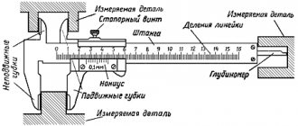
Considering that the pry bar, depending on the type, has a different shape, in most cases it resembles a crowbar with bends at one or both ends.
This is a hand tool, which is a metal rod with pointed or flat ends, which is highly durable and does not require maintenance or repair.
It is very difficult to break this tool, and due to its small size, it is convenient to use in limited space.
Dimensions and weight
Since the mount has a solid shaft and a simple design, its weight depends entirely on the material and dimensions.
The most common tool is 400 mm long, which is considered the most versatile due to the optimal ratio of parameters.
On the construction market you can find options with lengths from 300 mm to 800 mm or more.
Moreover, such a tool usually weighs from 200 g to 1 kg.
Material
For the manufacture of mounts, in most cases, medium carbon steel or titanium is used.
To work in a corrosive environment, tools are made from stainless steel.
The titanium mount differs from the steel version in its lighter weight and lower expansion coefficient.
It is more resistant to corrosion and is suitable for work in almost any weather and temperature conditions, due to this its price is much higher.
NOTE:
The service life of titanium tools is practically unlimited.
Maximum load
The maximum load for mounts depends on the material of manufacture, the size of the cross-section of the rod and its shape, it is measured in Newtons (N).
The indicator determines the load, above which the tool becomes damaged, for example, it breaks or bends.
As a rule, the manufacturer indicates 2 load options for products:
- percussion
- to bend.
It should also be noted that most manufacturers make a good margin for maximum load.
In other words, the tool is not damaged strictly when the specified values are reached.
Maximum load
This indicator changes in Newtons and is indicated on the packaging that comes with the tool. The ability of the crowbar to withstand loads without suffering fatal damage depends on it. The following types of bending and impact loads are distinguished.
But you should not assume that the product will suffer damage incompatible with operation if it reaches maximum performance. These values act as a guide. The manufacturer produces a product with a large margin of safety. But this does not mean that this statement is worth checking. Use the attachment in the area of application.
Types of mounts and price
Depending on the shape of the mount and design features, the following types are distinguished:
S-shaped (universal)
The most popular mount, which is found in almost every owner.
A tool that allows you to perform a wide range of work, from pulling out nails to tire fitting.
One end is made in the shape of a blade bent at 30° relative to the rod, and the opposite end is curved in a semicircle.
The version of the tool with a nail puller has a slot on the blade for gripping fastener heads.
In some cases, such slots may be at both ends.
Manufacturers often add an elongated hole at the bend of the blade, which makes it more comfortable to pull nails out of wood.
The price starts from 300 rubles.
L-shaped
Outwardly it resembles the option described above, but instead of a semicircle, the edge of the product is simply bent at an angle of 90 degrees or more.
It is convenient to use in places where space is limited, as a rule, the length does not exceed 400 mm.
Variations may also include a longitudinal cut at the curved end to remove nails.
The cost of the tool is approximately 250 rubles.
L-shaped with handle
One end is curved and has a slot for removing fasteners; on the opposite side, a rubberized handle is installed on the rod for convenience.
The tool is called a claw pry bar because of its intended purpose.
Straight
One end can be pointed, and the second is in the shape of a flattened, slightly curved blade.
This option is common among motorists, as it is used primarily for mounting truck tires and other repair work.
Cost – from 350 rubles.
Straight with handle
A variation of the straight type of tool, where a rubber handle is attached to the end opposite the blade.
This design is easy to use and does not slip out of your hands.
Price – from 450 rubles.
Flat
Frequent “guest” of auto shops.
Made from steel strip of various lengths.
Not suitable for complex work due to low strength.
Its other names are a car pry bar or just a pry bar, as it is great for dismantling tires.
The price of high-quality models is from 1000 rubles.
Curly
Also applies to automotive options and is intended for body work, in particular for repairing dents.
Spade mount
A generalized name for mounting racks, both sides of which are made in the form of a blade, or one side is curved with a hook for easy tire disassembly.
It can have either a flat or a cylindrical rod.
Check in operation
Pulling out nails
Let's start with the main function of a nail puller - pulling out nails. Since the tool is aimed specifically at working with small nails, let’s take the following sizes for the test: 1.2x20, 1.4x25.
Hammer the nails into the block. We do not finish until the end by about 2 mm.
The first one to go was a 1.2x20 nail.
The contact of the nail puller jaws with the nail head is tight.
We pull out the nail without any problems on the first try.
Next comes the 1.4x25 nail.
Again we observe close contact.
Pulling out a 1.4x25 nail is successful the first time.
What if you try our micronail puller on a full nail? For example, dimensions 2.5x60.
Here the insufficient length of the lever should already play a cruel joke (remember that the nail puller is only 30 cm long).
The width of the working groove is enough to firmly grip the nail.
It takes a fair amount of effort to pull out the nail. The same lack of leverage at the lever. The nail is eventually pulled out. But we can say for sure - for full-size nails and a nail puller you need a full-size one.
Analysis of wooden structures
The second function of a nail puller is the disassembly and dismantling of wooden structures.
We put together an improvised test bench - a board and a block (using 2.5x60 nails). And hammer the spatula into the joint. It is worth noting the successful profile of the nail puller - you can deliver precise and concentrated blows, driving the blade tightly between the pieces of wood.
For this exercise, the length of the lever was sufficient. But it should be noted that perhaps the not very powerful connection that the 2.5x60 nails provided had an effect
How to choose a mount?
When choosing a mini-crowbar, you should focus on its following parameters:
• Material. The weight, corrosion resistance and strength will depend on it. For automotive work, chromium-vanadium alloy is usually used. For other mounts, steel grades 30, 45, 50 are mainly used.
• Length – determines ease of use and functionality. The choice is made based on the task at hand. For example, dismantling window frames requires a 600 mm tool. To disassemble a motorcycle wheel, you will need a 300 mm long pry bar.
• Thickness and cross-sectional shape – determines the reliability and strength of the tool. The thicker, the better, it would seem. But as the thickness increases, so does the bulkiness. The best option is products with an oval cross-section. They are much stronger than round, hexagonal, square and flat options.
• Configuration – specific for each task. Sometimes it makes more sense to buy two mounts of different shapes and sizes.
• Ultimate load – selected depending on the task.
• Coating. Its presence is always a plus for the instrument. As a rule, mounts have a protective galvanic coating. The bright color of the mini-crowbar will prevent it from being lost in an open area, such as a construction site.
• Workmanship. It is difficult to assess the strength of a mount by appearance, but indirect factors can help with this. For example, the protective coating or paint must be applied evenly, without drips, and the edges of the product must be well processed and have the correct, even shape, without burrs. There should be no damage to the metal itself, including shells and chips.
• Price. Too high a price does not guarantee the quality of the instrument if it is from an unknown manufacturer.
Tool selection criteria
The main criteria for choosing a functional, convenient tool, photos of which can always be seen on the Internet, include:
- product material: steel or titanium;
- mount length;
- rod cross-section shape: circle or square;
- the presence of a handle, devices in the form of a nail puller;
- color of anti-corrosion coating;
- mount shape: straight, L-shaped, S-shaped;
- maximum load;
- manufacturer company;
- product price.
Please note: distinctive characteristics determine the cost of the product.
A titanium mount costs an order of magnitude higher than its tool steel counterpart. Hand tools can always be purchased in a set or as a separate product.
What you need to know about mounts?
A regular carbon steel pry bar is susceptible to corrosion.
For this reason, it requires appropriate storage conditions.
It is advisable to keep the instrument in a dry place.
In the case of a ventilated garage, it is better to wrap the product with thick paper or fabric.
If the product does not have a protective coating, you should apply it yourself.
Simply paint it with waterproof paint.
To protect the mount from moisture during long-term storage, the surface is coated with machine oil or even waste.
This method is effective, but impractical if you use the tool constantly.
If the mount begins to rust, it is easy to get rid of the deposits with emery cloth.
After treating the surface, it must be wiped with a dry cloth and lubricated with a small amount of machine oil.
Stage 5. Gearbox design
Now we need to create three separate panels that will contain the ball bearings for the shafts. But first, let's select the relative positions of the gears. When moving them, carefully check that they do not touch the shafts of other gears. I had to add a second set of gears with a 1:1 ratio to allow the aluminum shaft to run through the entire gearbox:
Once you've finished placing the gears, create a new work plane. This will be the gearbox housing. You can simply draw a rectangle around all the gears, or you can choose the shape of the plane so that it follows the general contours of the set. I chose the second option.
Create a new outline (sketch) on the newly created surface. Select "Project Geometry". Click on the holes of all the gears to project their shape onto the work surface:
After projecting the holes, you can create circles whose centers are the centers of the projections.
Now connect the circles with straight lines:
In the "Modify" section, select the "Trim" tool and delete all segments inside the resulting outer path:
Now create a straightened part at the bottom, to which a piano loop will then be attached, with the help of which we will align the plane of rotation of the mount with the plane of rotation of the Earth. You can also rotate the entire circuit first to make the gearbox look more harmonious. After this, draw a rectangle that will be inscribed at the extreme points of the crankcase:
Remove extra lines:
After creating the outline of the crankcase, you need to modify the projected holes so that they match the outer diameters of your bearings. I used two sizes: 28 mm (1.125″) and 20 mm (.75″):
Now you need to create a three-dimensional object (extrude) from this contour - the crankcase panel. The thickness should match your plastic (in my case 5mm, 3/16″). Then create two more copies of the panel - these are the front and back sides of the mount.
Stage 6. Design of the power transmission Now you need to design the drive pulley and holes for installing the stepper motor. Autodesk Inventor has a very convenient wizard for this.
In the “Design” tab, in the “Power Transmission” section, select “Synchronous Belts”:
Now create a pulley on the surface of the solid object. To transfer the rotation of the motor to the gearbox, I used a 1:3 ratio. You will need to select the number of teeth of each gear according to the values you selected:
Now place the power train into the gearbox. Connect the center point of the larger pulley to the shaft of the last gear of the gearbox. Rotate the power transmission in space so that it fits correctly into the gearbox:
Create holes for installing the motor according to the location of the power train. The center of the smaller pulley will be the center of the motor shaft:
Why is a pry bar called a crowbar?
Although people call a crowbar a crowbar, the origin of this word remains a mystery.
However, there are three versions that are not mutually exclusive:
- From Turkic, the consonant word “khomka” means a tool for picking locks. The pry bar copes both with the task of tearing the body of a padlock from the shackle and with rough opening of the door.
- In early thieves' jargon, a crowbar intended for breaking was simply called Foma, or Foma Fomich. Most likely, it was meant that the instrument acts as an accomplice, an assistant, for which it received its own name, which was transformed into “crowbar”.
- Another version is based on a certain burglar named Thomas, who opened locks with a crowbar. Perhaps the instrument is named after him.
Gear connection
First, we make holes of the required diameter in the center of each gear. Then we will attach the rotation axes of those gears that will be on the same shafts. Finally, we set the displacement of the planes between groups of gears connected to each other.
To make holes, open one of the components and create a new outline (sketch) on the gear plane. In the "Draw" section, select "Point" and place the point in the center of the gear. Finish creating the path and in the “Modify” section, select the “Hole” tool. Select the point you created and set the diameter of the circle to match your pin (in my case 6mm, 1/4″). Hole type: simple drilled. Do the same for all the other gears.
Now let's move on to connecting groups of gears by creating and linking their axes of rotation. In the Work Features section, select the Axis tool. Select one of the created holes and create a rotation axis. Do the same for those gears that should be connected to the first one. Having created a set of axes, in the “Position” section, click “Constrain”. Now constrain the two axes by clicking on both and applying “Constrain”. Groups of gears can be connected in any order. I started with the largest one and successively added smaller ones.
When you finish binding all axes, you need to position the planes of the gear groups. That is, space them out in space so that they can rotate freely:
Now we have a set of gears connected to each other correctly. You can start designing the gearbox.
How much does it cost to open a tire shop from scratch: calculating the break-even point
It is clear that when drawing up a business plan, an entrepreneur wants to calculate everything down to the penny, including the payback of the project. However, it is difficult to predict in this industry. On the forums you can find posts in which users answered how much tire fitting costs - they claimed that they even started with 200 thousand rubles, purchasing not new equipment. And there are also entrepreneurs who have invested several million. The average investment was 700 thousand rubles.
When you analyze a ready-made tire service business plan, you understand: “exhaust” does not always correlate with investment. The workshop sells the most profitable services in October and April. On peak days, for example, when the first snow falls, a tire service station can “change shoes” for up to 60 cars per day and receive an income of up to 50 thousand rubles. But, according to many businessmen, there are no more than 20 such days a year. The rest of the time, revenue hardly justifies fixed expenses.
With a normal start, the break-even point is reached in about six months. If the payback during this period is in question, you need to think about how to leave the tire shop business with minimal costs.
Despite the instability of income, businessmen who were able to survive during the first two to three years do not regret their choice.
Advantages
These include:
- high strength of products due to the performance characteristics of steel and titanium;
- ease of work in confined spaces;
- reliability and durability of the tool;
- ease of purchase, transportation, care, storage;
- wide areas of application;
- high resistance to mechanical stress and solar radiation;
- ability to withstand heavy loads;
- ergonomics, compactness and functionality;
- the cost of the mount corresponding to the costs of its manufacture and operational characteristics.
Please note: since the mount is made of metal, it is important to protect the tool from corrosion. To do this, store the pry bar in a dry room, or, if it is a cold basement or garage, wrap the tool in thick paper or fabric.. According to experienced craftsmen, a durable rod with a curved end is necessary for different occasions, and a wide range of its types provides the opportunity choose the best option that meets the wishes and financial capabilities of buyers
According to experienced craftsmen, a durable rod with a curved end is necessary for different occasions, and a wide range of its types makes it possible to choose the best option that matches the wishes and financial capabilities of buyers.
Watch the video in which a specialist talks about a classic crowbar with a nail puller, also known as a crowbar:
Useful tips
Seamless tiles: what are they, pros and cons, features of installation in the bathroom
When performing tire fitting work, the following recommendations should be taken into account:
- The extreme part of the lining should not be subject to serious mechanical stress. This is due to the fact that if you make a mistake, you can create serious problems for yourself in the future with the installation of tires. The most difficulties arise when installing tubeless tires.
- The edges are lubricated with grease to eliminate the possibility of damage to the rubber. It is worth considering that the tire should be lubricated every time it is installed. By using a lubricant, the likelihood of a rupture in the rubber is significantly reduced.
- At the time of installation, it is recommended to use a soap composition or another with lubricating properties. Their use greatly simplifies the installation process.
- When installing rubber on the disc, you need to ensure that there is no gap between them. This can lead to the tire starting to flatten or the outer part of the rubber to become damaged.
- On sale you can find quite a few different special kits for installing tires. Their use allows you to significantly simplify your work. Special kits include sealing harnesses and mounts of various sizes.
Advice from experienced people
How to make a machine with your own hands:
- The angle between the beading tip and the lever must be made sharp: the smaller it is, the better the rubber will fit on the disc. But this angle cannot be made too sharp, in which case the lever will scratch the disc when beading. We need to find the optimal degrees of angle.
- It is better to do a homemade tire changing machine with your own hands using drawings. You are quite capable of preparing them.
- Consider mounting it to the floor. The machine itself is lightweight, so it must be attached securely. If the floor is concrete, secure the machine with anchor bolts. If the floors are wood, use self-tapping screws.
- To reduce damage to rims and wheels, lubricate the tips and wheel rim with a thick soap solution. And don't forget to wash the wheel before work.
- Sometimes wheels may differ in the number of holes for fastenings and the distances between them. For such cases, we make metal adapters with studs 1 cm thick.
Build process
In order to avoid any problems during the assembly process, it is advisable to first study the drawings and dimensions of the homemade machine, as well as use the video instructions. Its construction is carried out in several main stages and does not require specific skills or significant time expenditure from the master.
You can assemble a tire service at home with your own hands by performing a number of simple manipulations:
Make a frame using profiled metal pipes or similar high-strength materials
It is strongly recommended to pay due attention to the shape of the base and compliance with dimensional parameters, since they directly affect the stability of the structure. Using a corner, install parallel structural elements. Install legs/wheels if desired. Secure the metal pipe and install the flange. Install fasteners for the lever. Steel plates are used for this purpose. Make a lever consisting of 2 elements - a shoulder and a paw.
When forming the base, it is strongly recommended to maintain a distance between the pipes of at least 70 cm, which will make it as stable as possible. When making fastenings, it is recommended to use material at least 2-3 cm thick, which will ensure its reliability. The flange is placed at a height of at least 40-60 cm from the fastening element.
Design and drawings
Having figured out how to do tire mounting yourself, you need to become more familiar with the basic design elements of this useful, effective device. Its basis is a frame made of metal pipes, which are placed parallel to each other. If desired, you can use stainless steel, which will avoid corrosion, increasing the service life of the product.
Tire fitting drawing
If you study the drawings, you can highlight other structural elements:
- a pipe that is used to attach the handle;
- a handle that allows you to comfortably use the lever;
- a riser used to place and secure the wheel when performing work.
In order to avoid corrosion, it is recommended to use protective coatings, such as special paints.
Required Tools
To complete the assembly work, you will need a standard set of tools, as well as a welding machine. The presence of the latter seems to be a necessary condition for the construction of the machine, since without it it will not be possible to assemble a strong, reliable structure that will be suitable for use. In addition, to extend the service life of the unit, the technician will need to use coloring compounds.
Assembly order
Having studied the instructions that allow you to build a homemade tire service with your own hands, you need to become more familiar with the procedure for assembling this kind of device. First of all, they begin to manufacture the base, on which many parameters of the finished machine depend.
Stage 11. Final product
Now you need to install the mount on a stable stand, it is needed to minimize possible vibrations. I took a round plywood board with a diameter of 50 cm and attached the mount to it using a piano loop. If the stand is not stable enough, then during a long exposure the mount may move slightly, and this will certainly affect the quality of the photographs.
I recommend attaching at least one bubble level to the stand to more accurately align the plane of rotation with the plane of rotation of the Earth. But if you use a green laser, you won't need levels. You can point the laser at the North Star and not bother with measuring the angle.
To mount the tripod head, I cut about 12mm off one of the M6 screws. Then I screwed the resulting pin into the adapter coupling, and screwed a piece of M12 pin into it. Now it was possible to attach the tripod head to the resulting adapter.
As an option, you can fasten the green laser with a tie to the adapter coupling and screw it onto one of the screws.