Protect your eyes | 08/23/2017
The main type of equipment of a welding station intended for work on direct current is a welding rectifier. Unlike household welding inverters, such units allow the implementation of significantly higher processing currents (and for a long time), as well as powering several welding stations.
Welding safety
When using the device, observe the following rules:
- Before starting welding, study the requirements of GOST and SNiP regarding the work process.
- Employees who do not have a certificate are not allowed to use the device.
- Do not operate the rectifier in tunnels, collectors, unventilated or gas-filled areas.
- Remove the protective casing only after disconnecting from the electrical network. Operating an open unit greatly increases the risk of electric shock.
- Do not move equipment connected to the network.
- When replacing the electrode, the power cable is disconnected from the outlet.
- During work, use protective equipment - work suit, gloves, welding mask.
Peculiarities
There is a myth that a welding rectifier cannot be used indoors. But this does not apply to the VDU 506 model. It feels great in the presence of natural ventilation (cracks, open windows, etc.). And even more: this device is capable of operating at very low temperatures down to -40 degrees.
However, this rectifier is not intended for welding in explosive atmospheres. The released vapors and gases can damage the welding machine or completely destroy it.
We are accustomed to thinking that a transformer and rectifier are difficult-to-use devices. This is largely true. But the VDU 506 model does not have many disadvantages. The arc ignites easily and burns stably, provided that you have provided sufficient voltage in the network to power the device. All this is possible thanks to improved characteristics. We can say that VDU 506 is a significantly modified version of the classic rectifier.
Design and principle of operation
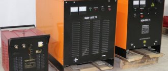
The general view of the rectifier and its overall dimensions are shown in the figure.
Designations
- “1” – overload sensor indicator;
- “2” – network power indicator;
- “3” – socket for connecting heating, when working with protective gas;
- “4” – socket for connecting the control unit of the semi-automatic device;
- “5” – place for installing the control unit of the semi-automatic device;
- “6” – Control unit of the device;
- “7” – button to enable/disable remote control;
- “8” – current indicator;
- “9” – voltage indicator;
- “10” – selection of external characteristics “hard/falling”;
- “11” – welding mode switch;
- “12” – regulator of output parameters;
- “13” – button to turn on the cooling system fan;
- “14” – button to turn off the cooling system fan;
- “15” – connection point for welding cables;
- “16” – connection point for grounding cables;
- “17” – toggle switch of the automatic switch;
- “18” – area for connecting network cables;
- “19” – handle for moving on the production site.
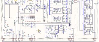
The electrical circuit diagram looks like this:
By its design, the VDU 506 welding machine is a step-down transformer with a semiconductor block that rectifies the incoming current. During operation, the diodes of the unit are subjected to heavy load, which causes an increase in temperature.
To remove heat, the devices have a cooling system, which consists of radiators and a fan. The rectifier benefits from smooth adjustment of the welding current. If necessary, it is possible to supply a special remote control for remote adjustment of the welding process.
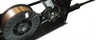
The factory set of supplied equipment includes:
- Straightener with handle and wheels for transportation.
- Set of current inserts.
- Passport with instructions from the manufacturer.
VDU-306MT “Track”
The welding rectifier with universal characteristics VDU-306MT is intended for use as a direct current power source for one welding station when:
- manual arc welding, cutting and surfacing of metals (MMA) with coated piece electrodes;
- mechanized welding with a consumable electrode in an environment of protective inert or active gases (MIG/MAG) gases, or using self-shielding flux-cored wire when the unit is equipped with an appropriate semi-automatic device;
- manual welding with a consumable electrode in an inert gas environment (TIG).
Design "Track" - on a platform with shock absorbers of increased vibration resistance - for work in harsh climatic conditions as part of mobile welding units.
The VDU-306MT rectifier is the latest development and differs significantly from all known rectifiers of the VDU series in its welding properties. The use of reliable power thyristors controlled by a microcontroller ensures the formation of external characteristics for various types of welding.
When performing manual arc welding with a coated electrode, VDU-306MT provides:
combined external current-voltage characteristic; smooth regulation of welding current in the range from 30 to 315A without intermediate switching; remote control of welding current at a distance of up to 30m; selection and installation of the slope of the working area of the external characteristic. This makes it possible to obtain both high current stability and the ability to quickly change it when manipulating the arc length, for example, to hold the pool when welding in vertical and ceiling positions; “hot start” mode - an adjustable increase in current when igniting the arc, which ensures almost perfect ignition, as well as high quality of the initial section of the seam; short circuit current boost mode
Depending on the type of electrode coating and the spatial position of the weld, on the one hand, low spattering is ensured, and on the other, energetic droplet transfer without sticking of the electrode to the pool, which is especially important when welding vertical and ceiling seams; anti-stick protection function, which limits the long-term short circuit current, thereby reducing the adhesion strength of the electrode to the part, preventing peeling of the electrode coating and facilitating re-ignition; limiting the open circuit voltage to a safe value of 12V;
Mechanized welding ensures:
- smooth, including remote, welding voltage adjustment;
- optimization of dynamic parameters when welding with short circuits, reducing spatter;
- the ability to connect and work with various types of feed mechanisms, including those intended for welding in installation conditions with self-shielding flux-cored wire.
Certified by AC Gazprom, included in:
|
| Certified by JSC VNIIST, included in: RD 08.00-60.30.00-KTN-050-1-05 “Welding during construction and major repairs of main oil pipelines.” |
For any welding method, operating parameters are specified digitally in absolute values. The current and voltage values characterizing the welding mode are displayed on digital indicators. Storage in memory and reproduction of preset modes, including those selected by the welder, are provided.
Operating temperature from -40 to +400С.
| Specifications: | MMA | MIG/MAG | TIG |
| Rated welding current, A (at PN-100%) | 315 | ||
| Rated arc voltage, V | 32 | 29 | 22 |
| Welding current control limits, A | 30 — 350 | 50 — 350 | 30 — 350 |
| Operating voltage regulation limits, V | 21 — 34 | 15 — 32 | 11 — 24 |
| Slope coefficient of external characteristics, V/A | 0,4 — 2,0 | ∞ | |
| Open circuit voltage, V | 12 | 85 | |
| Rated supply voltage, V | 380 | ||
| Rated frequency, Hz | 50 | ||
| Number of power supply phases | 3 | ||
| Power consumption, kVA | 23 | ||
| Overall dimensions, mm | 710 x 670 x 750 | ||
| Weight, kg | 182 |
Technical characteristics of welding rectifier VDU-506
Welding rectifier VDU-506 is a universal rectifier with thyristor control. Its versatility is manifested in its ability to provide:
- welding with coated electrodes;
- welding in shielding gases;
- flux cored wire welding;
- submerged arc welding;
- air arc cutting.
The rectifier is designed both for completing manual arc welding stations with piece metal electrodes, and for equipping semi-automatic machines of the PDG type for mechanized welding in a shielded gas environment of products made of low-carbon, low-alloy, carbon and corrosion-resistant steels on direct current. The straightener is adjustable and has a hard and falling external characteristic.
The rectifier is connected to a three-phase 380 V network and consumes 62 A from it at full load. The range of welding currents and operating voltages is quite wide: 50–500 A, 18–50 V.
| supply voltage, V | 3x380; 3x220 |
| rated welding current, A | 500 (PN=60%); 390 (MON=100%) |
| limits of welding current regulation, A | |
| for tough specifications | 60–500 |
| for falling characteristics | 50–500 |
| operating voltage regulation limits, V | |
| for tough specifications | 18–50 |
| for falling characteristics | 22–46 |
| open circuit voltage, V, no more | 85 |
| rated power, kVA, no more | 40 |
| welding cycle duration, min | 10 |
| overall dimensions, mm (LxBxH) | 820x620x1100 |
| weight, kg | 300 |
Expert comment:
By purchasing VDU-506, you receive:
- DC arc welding Welding from a rectifier is stable and stable, the technological effect in terms of the quality of seam formation and low spatter corresponds to the best samples. The rectifier ensures easy ignition and stable arcing at any current within the control range. The rectifier can work according to a given program with a manipulator or as part of a robotic complex. For this purpose, there is a special connector through which a standard signal (0–10 V) is supplied.
- Ease of use Smooth regulation of welding current (at falling) and voltage (at rigid external characteristics) is carried out by a resistor on the control unit (local regulation), as well as from a semi-automatic device or automatic device (remote regulation). The rectifier is equipped with a remote control for remote activation and regulation of welding current.
- To move within the welding area, the rectifier is mounted on a four-wheeled trolley with two handles. There are special handles with holes for lifting the rectifier.
- Transformer Features:
- designed for operation at ambient temperatures from –10 °C to +40 °C;
- versatility;
- ease of use;
- high arc stability;
- smooth regulation of welding current and voltage over the entire range without switching for each type of external characteristics;
- high technological properties;
- reliability and trouble-free operation.
Attention! The power source can be supplied at the consumer's request for a voltage of 220 or 380 V. At the user's request, the rectifier is equipped with a semi-automatic welding machine or automatic machine.. et.ua
et.ua
Welding rectifier VD 306 C1
The welding machine VD 306 C1 is designed to supply a welding arc with direct current for manual arc welding, surfacing and cutting of metals when powered from a three-phase alternating current network. Welding is carried out in open areas or indoor areas equipped for welding. It consists of a step-down welding transformer with a movable primary winding, a silicon rectifier unit with a fan, starting and protective equipment. Welding rectifier VD-306 S1 (380 V) is recommended for use in industrial enterprises.
| Features and advantages of VD-306 SELMA |
- All components of the rectifier are mounted on the trolley frame and protected by a sheet metal casing.
- The voltage required for the welding process, the falling external characteristic of the rectifier and the regulation of the welding current are provided by a three-phase transformer with increased magnetic dissipation.
- The rectifier has two ranges of regulation of welding currents.
- Within each range, smooth regulation of the welding current is carried out by changing the distance between the windings of the welding transformer.
- The external characteristics of the rectifier have a steeply falling working part with small multiples of the short circuit current (1.2-1.4) from the welding current at the rated operating voltage.
| Technical characteristics of VD-306 S1 |
| Supply voltage | 3x380 V |
| Rated network frequency | 50 Hz |
| Rated welding current | 315 A |
| Welding current adjustment range | 45-315 A |
| Duration of load | 60 % |
| Rated operating voltage | 22-36 V |
| Open circuit voltage | 71 V |
| Welding current control method | stepped, smooth |
| Power consumption | 24 kVA |
| Transformer windings | AL |
| Number of posts | 1 |
| dimensions | 610x710x640 mm |
| Weight | 127 kg |
| Design features of VD-306 S1 |
- A lead screw guide is passed through the upper yoke of the transformer.
- When the screw rotates, the primary winding moves and thereby changes its distance from the secondary winding.
- The conversion of alternating current into direct (welding) 1.A is carried out using a rectifier unit consisting of 6 diodes assembled using a three-phase bridge rectification circuit.
- Cooling of the welding rectifier is air, forced.
- To connect the rectifier to the power supply network, there is a plug connector on the front grille of the housing; for connecting the welding cable, there are also two power connector sockets, marked with “+” and “-” signs.
- On the front panel of the case there is a welding current range switch, control devices and control buttons.
| WE DELIVERY CONVENIENTLY Free delivery to the transport company | FAIR TRADE 100% guaranteed exchange of goods and money back | WE DO NOT Abandon OUR OWN We conscientiously carry out service and maintenance according to regulations | LOW PRICE GUARANTEED Found it cheaper? Let's reduce the price! |
Modernization of the mode switching circuit of the welding machine VD-306
Domestic manufacturers sin in that, as a rule, they do not provide feedback to their consumers.
Project documentation once put into production does not change for decades. Often, good engineering and design solutions are ruined by poorly implemented little things that the manufacturer never returns to improve. A simple and reliable welding machine VD-306, capable of working for years without maintenance. service at construction sites, has one typical weak unit - the mode switch. Usually the life of the device ends with the breakdown of this particular unit, because Often not only the switch itself burns out, but also the windings of the device’s transformer.
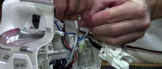
The photo (click on the image to enlarge the photo) shows a disassembled, worn-out switch. It can be seen that the contacts were burnt out, and the insulating partitions were deformed and charred.
I bring to your attention a simple technical solution for replacing the mode switch, which, by the way, is a standard solution for a large number of models of our domestic powerful welding machines made on the basis of a transformer.
The function of the switch is as follows - the secondary winding is switched to either a "Star" circuit or a "Triangle" circuit. We are replacing the switch with two magnetic starters with a permissible current on the contacts of 100 A. The diagrams below show the “Star” and “Triangle” connections with wire markings, and the photo shows installed PM12-100200 UZV starters (also with wire markings).
The concept of “rectifier” implies a device that converts alternating current from the network into DC welding current.
The introduction of various high-tech technologies in the design and development of devices for welding a wide range of actions allows us to move to a more advanced level of product production.
The welding rectifier VD-306 is a clear confirmation of this. The presented unit has proven itself exclusively on the positive side, as evidenced by the positive reviews of the owners.
Classification and labeling
All versions of welding rectifiers are divided according to the following parameters:
- According to the phase of the current used: single or three phase. The former are compact, but do not allow smoothing out significant voltage ripples and obtaining significant processing currents at the output, therefore they are used mainly for welding machines for household use.
- According to the method of controlling the strength of the welding current.
- According to the type of current-voltage characteristic.
- According to the current rectification circuit. It can be single-phase (used in low-power devices), three-phase or six-phase (the latter is used in high-power units exceeding 1000 kVA). In turn, three-phase rectification can be implemented using bridge or ring circuits.
- Depending on the number of posts served - single-post or multi-post.
The marking of welding rectifiers is regulated by the requirements of GOST 13821-77 (for single-station units) and GOST 18142-85 (for semiconductor units). It includes the letters VD (arc rectifier), the third letter U (universal), or M - multi-station. This is followed by the value of the welding current in amperes multiplied by 10, and (optionally) the series number. Thus, for example, the universal welding rectifier type VDU-504 is designed to produce direct current up to 500 A.
GOST 13821-77 establishes the following relationships between the energy characteristics of a welding rectifier and the duration of its continuous operation. In particular, in the range of welding currents 400...630 A, the minimum operating voltage cannot be less than 24...25 V, and duty cycle - more than 60%. At currents of 800 A or more, the minimum voltage is 26...34 V, and duty cycle can reach 100%.
The lineup
The company that produces this welding equipment offers a wide selection of devices of various modifications. The “VD” category of devices can be presented in various designs, depending on the requirements. Each new model is assigned its own article number, expressed in letter form.
1. VD-306I - inverter-type device, average cost 26,000 rubles.
The functionality of the inverter, which affects the operation of the welding arc, deserves special attention. The model is equipped with the following operating modes:
- “hot arc start”;
- "arc force";
- "anti-sticking".
Video:
2. VD-306D. These representatives of the “VD” family have found their application mainly in industrial production.
Such devices are distinguished by a high degree of reliability and unpretentiousness in difficult operating conditions. Equipped with thermal protection of the transformer and rectifier unit. Requires power supply with mains voltage 380V. The maximum output power is 25 kW. Cost - 110,000 rubles.
3. VD-306M1. Using this type of welding equipment, you can carry out work in AC or DC mode.
The maximum power of such a device is 24 kW, regardless of the welding mode. The main area of application is the industrial sector. Price - 45,000 rubles.
4. VD-306Sh. This type of rectifier can be connected to both industrial and domestic networks.
The maximum output power value is 23 kW. The average cost is 35,000 rubles.
Manufacturer companies, cost
Initially, the production of such equipment was launched at the JSC Electric Machine Building enterprise in Simferopol. Currently, the market is witnessing the emergence of an increasing number of enterprises focused on the production of devices of the “VD” series.
To answer the question: where is the VD-306 welding rectifier produced, just go to the website, which provides a list of the most common enterprises producing similar products.
The prices of the welding rectifier VD-306 today are within 30,000 rubles. The cost varies depending on the popularity of the manufacturer and component parts supplier.
PS Despite the fact that welding rectifiers VD-306 are somewhat inferior in some respects to their modern analogues, it should be noted that, other things being equal, such equipment is the best in its class in terms of price-quality ratio.
Design features and benefits
The main purpose of the VD-306 electric arc welding rectifier is to provide an uninterrupted supply of direct current to maintain the arc during various welding operations and metal cutting.
The devices of the presented type have found wide application both in industry and in the domestic sphere. The criterion for choosing such a device is a number of advantages inherent in a limited number of welders. Among them:
- uninterrupted operation, regardless of the network voltage. The voltage drop does not affect the output parameters of the device;
- the ability to connect equipment to an industrial or household network;
- the design of the protective casing allows the operation of this device in a wide temperature range;
- compact size;
- ease of maintenance;
- protection against spontaneous voltage surges;
- cooling system with forced air circulation;
- function of smooth adjustment of the output current.
Technical data
Equipment type VD-306 has the following technical characteristics:
- mains voltage – 380V;
- required network frequency – 50 Hz;
- rated operating voltage – 32V;
- operating current value – 315A;
- voltage value in idle mode – 60V-70V;
- switching duration – 60%;
- diameter of the actuator – electrode – 2 – 6 mm;
- temperature range – placement category “3” according to GOST 15150-69, for work in temperate climate areas at ambient temperatures from - 40ºС to + 40ºС and relative air humidity of no more than 80% (at a temperature of plus 20ºС);
- precious metal content – 0.017 grams of silver;
- overall dimensions – 560x510x660;
- weight – up to 104 kg.
Preparing the device: rules of use
Before starting work, you should inspect the integrity of the housing, insulation of cables and hoses. Check all contacts, terminals, clamps. After this, you should connect the case grounding and turn on the device.
Before starting work, you should set the settings and make a test seam. after that you can start working.
Welder of the 5th category of the central steelworks plant of Large-sized metal structures Bogdanov S.D.: “Dust settles on the windings and microcircuits of the equipment and leads to overheating and disruption of operation. If there is a compressor on site, the rectifier should be blown with a stream of compressed air through the air intake slots before operation. If work is carried out outdoors with normal dustiness, cleaning should be done once a week. Welding in an industrial enterprise with a large number of stations requires daily maintenance of the device. After this, you can begin checking connections and terminals. If there is no compressor, the dust is removed with a soft brush.”
Areas of use
The significant weight makes the device an unacceptable option for home work, despite the simplicity and reliability of the design. Welding inverters will cope much better with simple tasks in a summer cottage or garage. In addition, the cost of the rectifier is quite high for the average user.
Therefore, these devices are successfully used at various industrial enterprises that require the connection of thick-sheet products with deep welding of the seam. As practice shows, subject to timely maintenance and compliance with safety requirements, the device can operate for 20 years or more.
Design and principle of operation of a welding rectifier
The rectifier components include:
- Primary winding.
- Rectifier block.
- Cooling system.
- Control equipment unit, including a current stabilizer and automatic fuses.
- Protective housing with trolley.
- Control Panel.
The operation of the welding rectifier is as follows. The primary current from the network enters the input winding of the transformer. If a saturation choke is used as a rectifying device, then an electromagnetic field is first formed in its circuit, inducing the corresponding excitation current. This current is stabilized and transmitted through the rectifier unit to the electrode holder to initiate an electric arc.
Depending on the purpose, other rectification schemes can be used. For example, using power diodes (this is how current rectification is realized in VDU-504) or using thyristors. A thyristor current rectifier allows you to set the current value not stepwise, but smoothly, which is much more convenient.
Since semiconductor elements heat up intensely during operation, they are structurally enclosed in a ventilated housing. The straightening process itself can be organized according to various schemes:
- Conventional smoothing of current ripples (for low powers);
- Bridge, where current ripples are smoothed out in all three phases, and the oscillation frequency increases from 60 to 300 Hz;
- Ring, with two secondary windings (at the same rectification frequency, requires a more complex transformer device);
- Six-phase, with a symmetrical choke, due to which the pulsation frequency is halved (used for the most powerful models of welding rectifiers).
The functionality of rectifier units depends on the electric welding method used. For manual welding, a decreasing current-voltage characteristic is used, which is achieved either by increasing the resistance values on the transformer windings, or by inversion - using the feedback principle. Each of the schemes has its own limitations. When the resistance increases, it is necessary to use ballast rheostats. In turn, welding inverters are characterized by low processing currents and cannot operate with long duty cycle values.
Types of rectifiers
There are several types of rectifiers:
- welding thyristor rectifier VD 313 SE, VD 306;
- inverter power rectifier (welding);
- throttle;
- transistor (station wagon).
What is the difference between these devices?
Thyristor power supplies are suitable for various types of arc welding electrodes and can be used for welding work on rods.
Advantages:
- Higher efficiency compared to conventional rectifiers.
- Excellent arc characteristics, much smaller spark.
- Single row current control
- Easy to implement remote control function
- Good strength against voltage fluctuations
- Suitable for outdoor use.
- This is a multi-station welding rectifier - vdm - 1201, 2x313, vdm-1202 s, 1001, selma, BC ma, 6303 s.
The throttle rectifier is designed for welding in the most severe operating conditions (quarries, mines, pipelines, etc.). It provides semi-automatic welding and surfacing for currents up to 650A. In semi-automatic welding, the operating voltage is adjusted in steps. The single-station welding rectifier is represented by VDU 505, 504, VDU 506, DUGA professional and DUGA industrial.
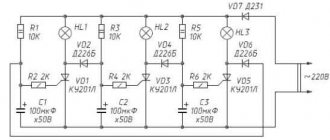
Circuit: Throttle rectifier
In addition to the main choke, the welding arc power supply system has another one built into the parametric section, which can significantly improve the quality of the weld due to the stabilization of welding. As a rule, in addition to the main power winding, an auxiliary winding is also used, which serves to regulate the inductance of the inductor and, thereby, controls the peak point during a short circuit or voltage surges.
The inverter rectifier is used to convert incoming alternating current into direct current, represented by models esab, man,. This current switches on and off very quickly, creating a pulsed, high-frequency DC current. Typical frequencies range from 10,000 to 20,000 Hz, but data up to 100,000 Hz is possible. The inverter, like the entire welding rectifier, needs to be checked every six months. The welding inverter rectifier is represented by the models electron 125, sun 600, 318m1, arc, neon (naks), afterburner, power, paton, terminator and anode (USSR).
Video of economical operation of a welding rectifier
Transistorized welding power sources have been developed for precise control of welding parameters. The speed of operation and response of transistors is very fast, hence such power sources can be adjusted to give any desired I-V reading between direct current and constant type voltage. In addition, the control system can be programmed to set the variable current and voltage during the actual welding operation. These technical features make the universal transistor welding rectifier particularly attractive for welding pipes, ventilation passages and shafts. Welding can be carried out using free-standing electrodes.
Almost every master has gasoline welding rectifiers (Esva, Loris). These are quite convenient portable devices, with which it is convenient to carry out work on the road or in the open air. There are very good reviews about the fubag welding rectifier, and its characteristics indicate that the device is also suitable for use in a local power supply network. In addition, these devices are often equipped with a portable charger.
If we distribute rectifiers by area of application, we get the following table:
| Application area | Rectifier name |
| For surfacing metal under a flux layer | vdu |
| For simultaneous power supply of several welding stations | VKSM |
| Used to power the welding machine when working with structural and alloy steels. Widely used in public utilities, everyday life, small workshops and workshops. | VDMSH |
| In cold car engines, an arc frequency universal device is often used. | VDUCH and VDC |
DIY welding rectifier
A rectifier for a welding machine is built around semiconductor elements, the essence of which is to pass electrical currents in only one direction. Today, three devices can be used in rectification circuits:
- diode (the best because it is the simplest; when using it, there is no need to introduce control units into the rectifier circuit);
- thyristor (for current to flow, it must receive a signal from the control system; when the passing current drops to zero or the voltage across it becomes less than in the next phase, the valve closes);
- transistor (a fully controllable “valve”, to open and close which you need to send a signal to the control electrode, and also the most expensive element).
It is best to use a diode, you might think, it is simpler and more convenient to use. However, there is one feature: when using diodes, the electrical circuit will require the introduction of a resistor to regulate the current. When using a transistor or thyristor, voltage regulation can be carried out by the control unit, through a delay in the opening and closing of the “valves,” reducing the voltage at the output of the rectifier and thereby reducing the current.
It is very important to choose any of the above elements with a margin. The actual current flowing through the circuit should be 1.5-2 times less than the rated current for which the semiconductor is designed. The maximum reverse voltage of the “valve” should be 2 times higher than the voltage on the secondary winding of the transformer
Otherwise, breakdowns of elements or failure due to overheating are possible.
The maximum reverse voltage of the “valve” should be 2 times higher than the voltage on the secondary winding of the transformer. Otherwise, breakdowns of elements or failure due to overheating are possible.
Using a diode bridge involves the use of a powerful resistance to regulate the welding current. The ideal option is to use a ready-made rheostat in the form of nichrome or nickel wire wound on a heat-resistant dielectric. You can choose a fechral acceleration stage for electric motors, or, as a last resort, steel wire, again wound on a dielectric. When choosing a resistance, you should assume that a fully introduced resistance into the circuit will reduce the current to zero. The length of the rheostat is calculated using the following formula:
- L=R/r*S;
- where R is the total resistance value required to reduce the welding current to zero;
- r is the resistivity of the material, taken from the reference book, optionally Wikipedia;
- S – section of the wound wire.
Another element that is sometimes used in a rectifier circuit is a choke. Calculating its parameters is quite difficult and time-consuming; determining a simple inductance value will not help. Even if you know the number of turns, the density of copper winding on the magnetic circuit, as well as the presence of a gap between the wire and the steel core, can have a significant impact on the inductance.
The way out of this situation is an experimental determination: we wind the choke in several layers with five or six taps, perform test welding and select the inductance based on the characteristic crackling sound, as well as splashes of molten metal. The less splashing and less crackling, the better. However, the introduction of inductance is not always required, since the inductance of the transformer windings may be sufficient to ensure the falling Volt-Amp characteristics of the welding machine.
How to make a straightener?
If you have minimal technical knowledge, making a welding rectifier with your own hands is not difficult. We first select a ready-made transformer with a step-down effect of the required range. Most often this is very difficult to do, and you have to wind it yourself. Detailed instructions for assembling the rectifier.
Welding rectifier circuit
We propose to make the simplest homemade welding diode rectifier. It must be assembled using a bridge circuit and mounted on a radiator so that the device is cooled all the time. The fact is that powerful diode lamps (VD type). To ensure a falling or hard characteristic, it is necessary to include a special inductor in the circuit. Next, a rheostat is attached to ensure smooth adjustment of the operation of the rectifier.
The electrical circuit of the rheostat is quite simple, you can wind it around the core with your own hands, you only need a simple copper or aluminum wire. But before work, you need to calculate the required resistance: the voltage adjustment depends on the diameters of the turns.
To make the task easier, you will definitely need not only a detailed instruction manual, but also a circuit diagram.
Appendix 3
Cleaning welds from slag should be done only after the seam has completely cooled, and always while wearing glasses with plain lenses. The windings are made of aluminum winding wire of the APSD brand.
The external characteristics are shown in Figures 5, 6 and 7. In manual arc welding mode, the voltage at the working clamps is 40 V. A stable arc, high-quality seam and reliable design make this device an ideal machine for any enterprise.
The current adjustment range depends on external characteristics.
A rectifier control unit is installed in the upper right part of the front wall. Claims about inconsistency of the used configuration with the diagrams and lists of the passport by the manufacturer will not be accepted. Precious materials specified in GOST 2.
Read more: Estimate for installation of electrical equipment sample
The electrical circuit diagram is shown in Fig. When operating the rectifier on a PC, the mode is selected by test welding. When welding on a PC with straight polarity, connect the cable connected to the electrode to the “—” connector. All repair and maintenance work should only be carried out after disconnecting from the mains.
Ground one of the output terminals of the rectifier depending on the welding polarity. To do this, you need to: - make a bracket according to the drawing given in Appendix 5; — make 3 pieces of cable with a cross-section of at least 10 mm2; — dismantle the cover covering the window for installing the circuit breaker; — install the switch in the window and secure it with a bracket; — connect the cables to contacts 1, 3 and 5 of the starter pos. In manual arc welding mode, the voltage at the work clamps is 40 V. Operation without a protective casing is prohibited. The appearance of the external characteristics is shown in Figures 5,6 and 7.
File information
If ventilation is disrupted, the KM2 starter, in the circuit of which there are KVZ relay contacts, disconnects transformer T1 from the network. To do this, you need to: - make a bracket according to the drawing given in Appendix 5; — make 3 pieces of cable with a cross-section of at least 10 mm2; — dismantle the cover covering the window for installing the circuit breaker; — install the switch in the window and secure it with a bracket; — connect the cables to contacts 1, 3 and 5 of the starter pos. The electrical circuit diagram is as follows: By its design, the VDU welding machine is a step-down transformer with a semiconductor block that rectifies the incoming current. When servicing and operating the rectifier, it is necessary to comply with the requirements of regulatory documents on occupational safety in force in the region where welding work is performed.
Each rectifier is designed for only one of those indicated in the table. Precious materials specified in GOST 2. The power rectifier unit consists of six thyristors VS1-VS6 7 type T-T, assembled according to a six-phase rectification circuit with an equalizing reactor. When the rectifier is properly cooled, air should be drawn in from the valve side. VDU 506 in real factory conditions - repair (spontaneous shutdown).