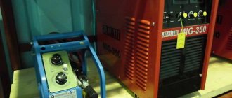
A unit designed for welding products is considered to be a semi-automatic welding machine. Such devices can come in various types and shapes. But the most important thing is the inverter mechanism. It is necessary that it be of high quality, multifunctional and safe for the consumer. Most professional welders do not trust Chinese products and make the devices themselves. The manufacturing scheme for homemade inverters is quite simple. It is important to consider for what purposes the device will be manufactured.
There are inverters for:
- Welding using flux-cored wire;
- Welding with various gases;
- Welding under a thick layer of flux;
Sometimes, to achieve a high-quality result and obtain an even weld, the interaction of two devices is necessary.
Inverter devices are also divided into:
- Single-hull;
- Double-hull;
- Pushing;
- Pulling;
- Stationary;
- Mobile, which includes a trolley;
- Portable;
- Designed for beginner welders;
- Designed for semi-professional welders;
- Designed for professional craftsmen;
Inverter circuit:
What will you need?
A homemade device, the circuit of which is very simple, includes several main elements:
- A mechanism with the main function responsible for controlling the welding current;
- Mains power supply;
- Special burners;
- Convenient clamps;
- Sleeves;
- Cart;
Scheme of welding using a semi-automatic device in a protective gas environment:
The master will also need:
- A mechanism that provides wire feeding;
- A flexible hose through which wire or powder will be supplied to the weld under pressure;
- Bobbin with wire;
- Special control device;
Types
Modern manufacturers today offer two types of welding hoses. This could be a hose itself or a burner. However, the appearance of these products is no different from each other. Both of these names refer to the same accessory.
Thus, a semi-automatic welding torch-sleeve consists of three main elements. This is the burner itself, the hose, as well as connectors for connecting them. Unfortunately, it is now difficult to find sleeves for sale separately. But you can purchase almost all the components of the design or find analogues.
Principle of operation
The operating principle of the inverter includes:
- Adjusting and moving the burner;
- Control and monitoring of the welding process;
When the unit is connected to the electrical network, a conversion of alternating current to direct current is observed. For this procedure you will need an electronic module, special rectifiers and a high-frequency transformer. For high-quality welding, it is necessary that the future unit has parameters such as the feed speed of the special wire, current strength and voltage in identical balance. For these characteristics, you will need an arc power source that has current-voltage readings. The length of the arc must be determined by the specified voltage. The wire feed speed directly depends on the welding current.
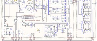
Homemade device diagram:
The electrical circuit of the device provides for the fact that the type of welding greatly influences the progressive performance of the devices as a whole.
Electrical diagram of a homemade device:
DIY semi-automatic - detailed video
Rework algorithm
The vast majority of components are used without significant modifications. Re-equipment will be required for the filler material feeder, since the feed rate of the filler through the flexible hose must match the melting rate of the filler metal. It is necessary to take into account the adjustment option in the mechanism, because the speed varies based on the type of metal being welded, the type and cross-section of the filler material.
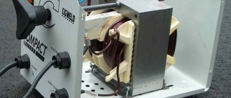
In a working inverter, first of all, the transformer device included in its structure should be rearranged. It is covered with an additional layer consisting of a copper strip and paper with a heat-sensitive coating.
Do not use ordinary copper wire for the transformer device. During the welding cycle, it heats up too much and can stall the operation of the entire semi-automatic welding unit.
The secondary winding of the transformer device also requires improvement. It is covered in 3 layers of thin sheet steel, insulated with fluoroplastic tape. The ends of the wound winding are connected by soldering. After performing these steps, electrical conductivity increases significantly.
An important component is the fan, which will cool the unit, protecting it from excessive heating.
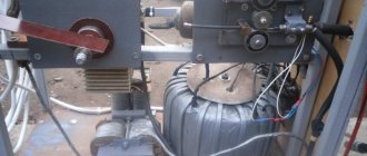
A current converter for manual electric welding very easily becomes a power source for a semi-automatic unit. The working device can not be disassembled, and all auxiliary equipment can be located in another building. It contains a reel with filler material, which rotates freely on the drum, and a feeding device. On the side of the casing there is a speed converter for the filler material and a connector for connecting the guide hose.
A used PC system case will easily do. It will turn out neat and concise.
The parameters of the electric current can be adjusted on the inverter, therefore, the “positive” terminal is connected to the part from it.
“Minus” is removed from the inverter and inserted into a new supporting shell. Here it is connected to the terminal of the supply hose. The main thing is that the filler material is connected to this potential.
The hose for supplying the protective gas mixture, which runs from the cylinder to the burner gun, is also fixed in the housing. If you use the valve from the car's windshield wipers, the gas mixture supply setting will appear.
The presented assembly is simple to implement, and the inverter can be used in parallel for manual electric arc welding and as a power source for a welding unit made at home, operating in a semi-automatic mode.
Created plan
Any scheme of a homemade device provides a separate sequence of operation:
- At the initial level, it is necessary to ensure preparatory purging of the system. It will accept the subsequent supply of gas;
- The arc power source must then be started;
- Feed wire;
- Only after all actions have been completed will the inverter begin to move at the specified speed.
- At the final stage, the seam should be protected and the crater welded;
Preparing the transformer
Your attention must be paid to the feeding mechanism. Using this device, the electrode wire must be fed. Due to the fact that this mechanism breaks down most often, high-quality calculations should be made. It is important to note that an increase in current in most cases leads to fire of the electrode. This causes severe damage to the product. But if the current is very weak, then it will not be possible to make a full-fledged unit. The resulting weld will be unreliable. Therefore, at this stage of preparation it is necessary to correctly perform all calculations.
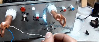
How to monitor the correct operation of equipment
In order for the semi-automatic welding machine that you assembled with your own hands to serve you for a long time, it is better to constantly monitor the temperature conditions of the inverter. To carry out such control, you need to press two buttons simultaneously, after which the temperature of the hottest inverter radiator will be displayed on the indicator. The normal operating temperature is considered to be one whose value does not exceed 75 degrees Celsius.
If this value is exceeded, then, in addition to the information displayed on the indicator, the inverter will begin to emit an intermittent sound signal, which should be noted immediately. In this case (as well as if the temperature sensor breaks or shorts), the electronic circuit of the device will automatically reduce the operating current to 20A, and a sound signal will be emitted until the equipment returns to normal. In addition, a malfunction of self-made equipment may be indicated by an error code (Err) displayed on the inverter indicator.
Setting the welding mode on the Resanta inverter
Power supply
Repair or fabrication of a structure includes a power source. Such a device can be a rectifier, inverter or transformer. It is this part that affects the volume and cost of the welder. Inverter power supplies are considered to be the most professional and high-quality devices.
Power supply diagram:
Control board
To create an inverter, a special control board is required. This device must have the following components installed:
- A master oscillator including a galvanic isolation transformer;
- The node with which the relay is controlled;
- Feedback blocks responsible for mains voltage and supply current;
- Thermal protection block;
- Antistick block;
Control unit printed circuit board:
Repair/modification of electrode wire feed speed device
Inverters are considered reliable devices. But if care is not taken care of, the devices may fail. The devices may require repairs. In most cases, the main cause is a broken regulator. When the first problems occur, the breakdown affects the further operation of the device. Therefore, in order to avoid future repairs, you should devote as much time as possible to high-quality assembly of the device.
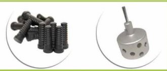
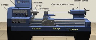
The unit diagram includes a pressure roller. It is equipped with a special wire pressure level regulator. The unit also contains a wire feed roller, which has two small recesses. The welding wire should come out of them. The use of wire with a diameter of up to 1 mm is allowed. Immediately after the regulator there is a solenoid that controls the gas supply.
The regulator is considered a large element. It is secured with small bolts. Therefore, the fastening is extremely unreliable. The unit may warp, which may lead to malfunction. It is because of this reason that the device often breaks down and requires additional repairs.
Remodeling methods
To begin with, let's consider possible options for converting an inverter into a semi-automatic welding machine.
To create a semi-automatic device, you will definitely need a so-called head unit. This is, in fact, a welding machine, which will form the operating parameters for the occurrence of an arc discharge. Not every inverter model is suitable as such a head unit.
It is necessary to choose a sufficiently powerful welding machine. Its current-voltage characteristics can be changed using a pulse-width modulation controller. However, firstly, not every home craftsman has such a device. Secondly, the measurement process is very long and labor-intensive. Finally, only a person with a sufficiently high level of knowledge in electrical engineering can carry out all the research.
Since the option with a PWM controller will not be available to the average welder, it is recommended to take a simpler route. Firstly, the selected donor device must normally perform all necessary operations. Secondly, to create a homemade semi-automatic you will need a choke. This part, intended for fluorescent lamps, can be purchased at any spare parts store. The inductor output voltage is used as a feedback input. How exactly to make a connection diagram and carry out the necessary installation operations is shown in the video below.
This option for creating a homemade semi-automatic machine is suitable only for happy owners of high-quality equipment. Namely, inverters capable of operating in a strictly specified current-voltage characteristic mode. Welders of this class are expensive, but they are most suitable for solving the task.
To make your own semi-automatic device, you will need:
- buy a wire feeder, complete with all the necessary wires and switching connectors;
- connect the feed mechanics to the inverter welding machine;
- select the current-voltage characteristic to work with a specific type of wire.
Wire feeder from Aliexpress
In essence, the feed mechanism acts as an attachment that expands the capabilities of the welding inverter. However, such a scheme has increased reliability and does not require special knowledge from the user. In addition, the resulting semi-automatic machine shows the maximum level of flexibility and unpretentiousness: it can be quickly configured to work with a specific material and wire.
This method will require considerable preparation from the user. Firstly, he will need to find a non-average inverter welding machine of suitable power. It is necessary to select the simplest possible donor of a certain class. The ideal device would be one that:
- there is a shunt at the output;
- a current transformer is used in the primary conversion block;
- ZX-7 layout.
It is recommended to choose devices without additional control options and functionality to make the life of the welder easier. The inverter should not have any hot starts, simple ignition, or arc forced.
To create your own homemade semiautomatic device, you will need to accurately set the current-voltage parameters of the selected inverter. You will also need to adjust the current increase. The order and list of required work is not universal. It differs for different inverter models.
Volt-ampere characteristics of the welding inverter
DIY choke
In order to make a choke, you will need a transformer, an enamel wire with a diameter of more than 1.5 mm. Insulation is wound between the layers. Using an aluminum bus with dimensions of at least 2.5x4.5 mm, 24 turns are wound. The remaining ends of the bus remain 30 cm each. The core is laid using pieces of textolite with a gap of at least 1 mm. It is also allowed to wind the inductor on iron from an old tube color TV. But such a device can only have one coil. Such a device can stabilize the welding current. The finished product must output a minimum of 24 V at 6 A.
Welding torch
This device is designed to supply electrode wire, carbon dioxide and arc voltage to the required welding area. The purpose of the device is to close the circuit, which ensures the supply of welding wire to the shielding gas.
Welding torch:
For the best quality effect, it is recommended to purchase a ready-made gun. The device must include hoses for supplying welding wire and shielding gas.
Semi-automatic Sanych
To make the transformer, Sanych used 4 cores from TS-720. The primary winding was wound with copper wire Ø 1.2 mm (number of turns 180+25+25+25+25), for the secondary winding I used an 8 mm2 busbar (number of turns 35+35). The rectifier was assembled using a full-wave circuit. For the switch I chose a paired biscuit. I installed the diodes on the radiator so that they would not overheat during operation. The capacitor was placed in a device with a capacity of 30,000 microfarads. The filter choke was made on a core from TS-180. The power part is put into operation using a TKD511-DOD contactor. The power transformer is installed TS-40, rewound to a voltage of 15V. The roller of the broaching mechanism in this semi-automatic machine has a Ø 26 mm. It has a guide groove 1 mm deep and 0.5 mm wide. The regulator circuit operates at a voltage of 6V. It is sufficient to ensure optimal feeding of the welding wire.
How other craftsmen improved it, you can read messages on various forums dedicated to this issue and delve into the nuances of manufacturing.
Cart
The cart can be made by yourself. The use of ready-made structures is also permitted. You can make single-level, two-level and three-level products. For convenience, tools and materials that will be needed for work are stored on the upper level. For easy movement, the cart includes wheels with a diameter of at least 5 cm.
Homemade cart with several variations:
Welding modes in carbon dioxide:
A semi-automatic device differs from a conventional device in its wire feed mechanism. Therefore, such a unit is considered the most complex device. Repair will be necessary if the feed mechanism breaks down.
Another useful manufacturing option
Required tools and materials
To make a semi-automatic machine from an inverter, you need to prepare the following equipment:
- Inverter. When choosing this component, it is important to pay attention to such an indicator as the strength of the generated current. It is important that its level is not less than 150A.
- Wire feed mechanism for semi-automatic machine. It is he who will be responsible for the continuous supply of filler wire, which should lie evenly, without jerking or slowing down.
- Burner. This component is responsible for melting the filler wire.
- Supply hose. Through this hose the filler wire will be supplied to the work area.
- Gas hose. Necessary for introducing a shielding gas, usually carbon dioxide, into the welding area to protect the weld from oxidation.
- Coil. The filler wire must be located on the reel, with which it must be fed without delay.
- The electronic unit. It is necessary to control the operation of a semi-automatic machine; with its help, the current supply, voltage and speed of work are regulated.
Most components can be found in high quality without much effort and can be used without major modifications. But special attention should be paid to the feed mechanism. To ensure that the welding work meets all requirements, the wire feed through the flexible feed hose must be carried out in accordance with its melting rate.
Considering the fact that a semi-automatic machine can be used to bond various metals, the welding speed and type of filler wire can vary significantly. That is why it is very important to be able to adjust the speed of the feeding mechanism.
The choice of wire depends on the purpose of welding work and the metal being processed. The filler wire differs not only depending on the material, but also on the diameter. You can usually find wire in diameters of 0.8, 1, 1.2, and 1.6 mm. The corresponding wire must first be wound onto a reel. The quality of the finished seam directly depends on the quality of this preparatory work.
Then the coil is attached using a special mount or a homemade structure to the device. During work, the wire is automatically unwound and fed into the work area. This allows you to significantly simplify and speed up the process of joining metal elements using welding, making it more efficient and easier for beginners.
Manufacturing of semiautomatic welding machines
The control unit consists of a microcontroller necessary to stabilize the current. It should be noted that it is this component element that is responsible for the ability to adjust the current during work.
Converting a welding inverter into a semi-automatic machine
To make a semi-automatic welding inverter, you need to subject the device to some manipulations. The device is wrapped in copper strip with thermal paper winding. It is important to note that ordinary thick wire will not work. It will get very hot. The cooling system may not be able to cope with the load, which will lead to severe overheating of the device.
The secondary winding should consist of three layers of tin. Each layer should be carefully insulated. To do this, use fluoroplastic tape. The ends of the winding must be soldered together. This procedure allows you to increase the conductivity of currents.
Oscillogram of welding voltage and current on reverse and direct polarity:
Any homemade device does not respond well to the presence of dirt and dust. Therefore, such devices should be cleaned at least once every 4-6 months. The intensity of cleaning should depend on the number of uses. Otherwise, the device will have to be repaired annually.
Approximate modes for welding butt seams using a semi-automatic machine:
The main advantage of such devices is considered to be low weight. It is also possible to use both AC and DC power. The units can weld non-ferrous metals, as well as cast iron. The disadvantages include the low temperature range. Do-it-yourself semi-automatic welding cannot be used at temperatures below 15°C. Therefore, such devices are not suitable for cold regions and for the winter period. Basically, such inverters are used outdoors in the summer or indoors. Homemade structures are perfect for welding small structures at home. For professional welding and for wide production, it is recommended to buy ready-made inverters.
Methods of creation and algorithm of actions
If you have an old inverter on hand, assembling the semi-automatic device will not take much time. You can also make an efficient device from a transformer.
From inverter
To convert an inverter into a welding device, you need to prepare:
- Means for supplying current and filler wire.
- Burner for forming a gas environment.
A pistol grip can be used as a clamp for electrodes. The wire will move along the hose channel that connects the torch to the equipment. The inverter system must record a constant output voltage.
The prepared inverter needs to be slightly altered. To do this, wrap its transformer with copper wire and thermal paper. It is impossible to use a core with insufficient thickness, since it will heat up during operation of the device.
You can easily convert the inverter into a welding device.
The secondary winding requires additional protection with 3-layer sheet metal. To increase current conductivity, you need to solder the ends. A ready-made welding inverter is suitable as a power source, which should be connected to the housing with other components.
At the stage of creating a feed mechanism, the types and parameters of consumables should be taken into account. Finished parts are sold in electrical goods stores.
In addition, you can make the mechanism yourself, using an electric motor from car wipers, a pressure shaft with a spring, 3 bearings and metal plates 1 cm wide. All parts should be secured on a textolite stand 5 mm thick.
The burner assembly is a consumable item with a service life of no more than 1 year. The operating principle of different devices is identical.
The burner design contains the following parts:
- Support with handle.
- Nozzle.
- Fastening elements.
- Tips.
The parts of the device are heated during welding. The tip and nozzle are particularly exposed to high temperatures. The material they are made of determines their service life.
When remaking an inverter, it is important to correctly connect the control element, which ensures the conservation and conversion of current. The power cable should be connected to the gas supply and wire extraction valve. To do this, you need to install an inverter with a rectifier.
When remodeling, it is important to connect the control element.
The interaction between the electric motor and other system components is created by a 12 V intermediate relay.
After preparing all the components, all that remains is to assemble the device according to the following algorithm:
- Connect the inverter to the power and control units.
- Thread the device with wire and make sure that it is evenly distributed over the surface.
- Connect the burner to a hose that connects to the cylinder. Start the inverter and evaluate the gas supply.
- Install converters on radiators.
- In the zone of greatest heating, attach a temperature sensor that will deactivate the system in case of overheating.
- Connect the power components to the control unit.
- Connect the device to the network, check the output current (it should not be more than 120 A).
From a transformer
If you have an unnecessary welding transformer on hand, you can turn it into a full-fledged semi-automatic machine. The device with direct current and built-in rectifier does not need modification. The variable voltage model will have to be redone.
For the upcoming assembly you need to prepare:
- Filler wire feed unit.
- Welding current generation device.
- Power unit.
- Burner.
- Support mechanisms.
- Clamps.
- Sleeves.
You can make a full-fledged semi-automatic device from a transformer.
A transformer can be used as a power source. It determines the power and performance of the entire system. The housing can be made from a box or box of a suitable size. It is better to make it from plastic or metal sheets. The housing must contain transformers that are connected to the primary and secondary windings.
To cool the semiautomatic welding machine, fans should be installed. They can be placed on the sides of the housing, opposite the transformer.