Unified inch threads of the UN standard (UNC, UNF and UNEF) are widespread in America and Canada, where the inch measurement system is used. Here this standard is the main one for bolts, screws, nuts and many other fasteners used in mechanical engineering. Their production is regulated and controlled by ASME and ANSI organizations.
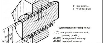
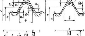
American thread has the same profile with an apex angle of
60°
as the metric ISO standard, but its main parameters are expressed not in millimeters, but in inches. Depending on the frequency of turns, it can also be large (main) UNC, small UNF and superfine UNEF. The number of turns per inch is called pitch TPI, while in the metric the pitch refers to the distance between adjacent vertices of the helix P (mm). These parameters are related by the ratio: P = 1″/ TPI (remember that 1″ = 25.4 mm).
Legend
The thread designation indicates its outer diameter - D
, followed by a pitch -
TPI
(threads per inch) and its type -
UNC
or
UNF
.
For diameters less than 1/4″,
the size is indicated by an integer from
0 to 12
, which appears after the
#
or
No
. Each number corresponds to a specific external D, the exact value of which can be found in the reference table. For all other diameters above 1/4″ this value is expressed in inches.
American thread with coarse pitch - UNC
| Thread size | Threads per inch | D - outer diameter | Dp - average diameter | Di - internal diameter | Thread pitch, mm | |
| inches | mm | millimeters | ||||
| #1 | 1,85 | 64 | 1,85 | 1,6 | 1,42 | 0,40 |
| #2 | 2,18 | 56 | 2,18 | 1,89 | 1,69 | 0,45 |
| #3 | 2,51 | 48 | 2,51 | 2,17 | 1,94 | 0,53 |
| #4 | 2,84 | 40 | 2,84 | 2,43 | 2,16 | 0,64 |
| #5 | 3,17 | 40 | 3,18 | 2,76 | 2,49 | 0,64 |
| #6 | 3,50 | 32 | 3,51 | 2,99 | 2,65 | 0,79 |
| #8 | 4,16 | 32 | 4,17 | 3,65 | 3,31 | 0,79 |
| #10 | 4,83 | 24 | 4,83 | 4,14 | 3,68 | 1,06 |
| #12 | 5,49 | 24 | 5,49 | 4,8 | 4,34 | 1,06 |
| 1/4 | 6,35 | 20 | 6,35 | 5,52 | 4,98 | 1,27 |
| 5/16 | 7,94 | 18 | 7,94 | 7,02 | 6,41 | 1,41 |
| 3/8 | 9,53 | 16 | 9,53 | 8,49 | 7,81 | 1,59 |
| 7/16 | 11,1 | 14 | 11,11 | 9,93 | 9,15 | 1,81 |
| 1/2 | 12,7 | 13 | 12,70 | 11,43 | 10,58 | 1,95 |
| 9/16 | 14,3 | 12 | 14,29 | 12,91 | 12,00 | 2,12 |
| 5/8 | 15,9 | 11 | 15,88 | 14,38 | 13,38 | 2,31 |
| 3/4 | 19,1 | 10 | 19,05 | 17,40 | 16,30 | 2,54 |
| 7/8 | 22,2 | 9 | 22,23 | 20,39 | 19,17 | 2,82 |
| 1 | 25,4 | 8 | 25,40 | 23,34 | 21,96 | 3,18 |
| 1 1/8 | 28,6 | 7 | 28,58 | 26,22 | 24,65 | 3,63 |
| 1 1/4 | 31,8 | 7 | 31,75 | 29,39 | 27,82 | 3,63 |
| 1 3/8 | 34,9 | 6 | 36,93 | 32,17 | 30,34 | 4,23 |
| 1 1/2 | 38,1 | 5 | 38,10 | 35,35 | 33,52 | 4,23 |
| 1 3/4 | 44,4 | 5 | 44,45 | 41,15 | 38,95 | 5,08 |
| 2 | 50,8 | 4 1/2 | 50,80 | 47,13 | 44,69 | 5,64 |
| 2 1/4 | 57,1 | 4 1/2 | 57,15 | 53,48 | 51,04 | 5,64 |
| 2 1/2 | 63,5 | 4 | 63,50 | 59,38 | 56,63 | 6,35 |
| 2 3/4 | 69,9 | 4 | 69,85 | 65,73 | 62,98 | 6,35 |
| 3 | 76,2 | 4 | 76,20 | 72,08 | 69,33 | 6,35 |
| 3 1/4 | 82,5 | 4 | 82,55 | 78,43 | 75,68 | 6,35 |
| 3 1/2 | 88,9 | 4 | 88,9 | 84,78 | 75,68 | 6,35 |
| 3 3/4 | 95,2 | 4 | 95,25 | 91,13 | 88,38 | 6,35 |
| 4 | 101,6 | 4 | 101,60 | 97,48 | 94,73 | 6,35 |
General information, markings
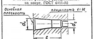
NPT pipe threads are available in two configurations - external and internal. A pipe fitting with such a thread has the shape of a narrowed cone; due to this structure, increased strength of the connection between two pipeline elements is ensured.
The conical standard is practically not used in water supply systems, since in this case its safety margin is excessive. The main areas of application for NPT are mechanical engineering, machine tools, oil and gas industries, and this connection is also widely used in hydraulic systems.
To connect two pipes, a conical thread is formed on the fittings of each of them, with an internal cone cut on one and an external cone on the other. The angle of inclination of the cone is unified and amounts to 3034'49”, which is equal to the taper (C)1:16.
There are two types of tapered thread dimensions - inch and metric, depending on which the nomenclature designation of NPT connections in diagrams and drawings differs. If one of the sides of the pipe or fitting on which the cone is cut is metric, the abbreviation NPT-E is used, but if both sides of the cones being connected are inch, the additional abbreviation is not used and simply NPT is indicated.
Appearance of tapered NPT thread
Specifications for NPT thread sizes and configurations are given in the following international standards:
- ANSI/ASME B36.10M;
- BS 1600, 10255;
- DIN 2999.
There are also domestic regulatory documents for conical connections:
- GOST No. 6111-52 “Inch conical thread with a profile angle of 60 degrees”;
- GOST No. 6211-81 “Basic standards of interchangeability - conical pipe threads.”
Today, specialized stores offer a wide number of adapters and adapters that have a cylindrical thread on one side and a conical thread on the other, which allows you to easily use pipes with American standard fittings.
American fine pitch thread - UNF
| Thread size | Threads per inch | D - outer diameter | Dp - average diameter | Di - internal diameter | Thread pitch | |
| inches | mm | millimeters | ||||
| #0 | 1,52 | 80 | 1,52 | 1,32 | 1,18 | 0,32 |
| #1 | 1,85 | 72 | 1,85 | 1,63 | 1,47 | 0,35 |
| #2 | 2,18 | 64 | 2,18 | 1,93 | 1,76 | 0,40 |
| #3 | 2,51 | 56 | 2,51 | 2,22 | 2,02 | 0,45 |
| #4 | 2,84 | 48 | 2,84 | 2,50 | 2,27 | 0,53 |
| #5 | 3,17 | 44 | 3,18 | 2,80 | 2,55 | 0,58 |
| #6 | 3,51 | 40 | 3,51 | 3,09 | 2,82 | 0,63 |
| #8 | 4,17 | 36 | 4,17 | 3,71 | 3,4 | 0,71 |
| #10 | 4,83 | 32 | 4,83 | 4,31 | 3,88 | 0,79 |
| #12 | 5,49 | 28 | 5,49 | 4,90 | 4,40 | 0,91 |
| 1/4 | 6,35 | 28 | 6,35 | 5,76 | 5,37 | 0,91 |
| 5/16 | 7,94 | 24 | 7,94 | 7,25 | 6,79 | 1,06 |
| 3/8 | 9,53 | 24 | 9,53 | 8,84 | 8,38 | 1,06 |
| 7/16 | 11,1 | 20 | 11,11 | 10,29 | 9,74 | 1,27 |
| 1/2 | 12,7 | 20 | 12,70 | 11,87 | 11,33 | 1,27 |
| 9/16 | 14,3 | 18 | 14,29 | 13,37 | 12,76 | 1,41 |
| 5/8 | 15,9 | 18 | 15,88 | 14,96 | 14,35 | 1,41 |
| 3/4 | 19,1 | 16 | 19,05 | 18,02 | 17,33 | 1,59 |
| 7/8 | 22,2 | 14 | 22,23 | 21,05 | 20,26 | 1,81 |
| 1 | 25,4 | 12 | 25,40 | 24,03 | 23,11 | 2,12 |
| 1 1/8 | 28,6 | 12 | 28,58 | 27,20 | 26,28 | 2,12 |
| 1 1/4 | 31,8 | 12 | 31,75 | 30,38 | 29,46 | 2,12 |
| 1 3/8 | 34,9 | 12 | 34,93 | 33,55 | 32,63 | 2,12 |
| 1 1/2 | 38,1 | 12 | 38,10 | 36,73 | 35,81 | 2,12 |
Can you supply inch fasteners with small diameters?
GOST R 50864-96 conical locking thread for drill string elements. profile, dimensions, technical requirements
These dimensions start from #1 (1.854 mm)
up to #12 (5.436mm)
TK Hardware company can supply it to order for you.
The lead time for these items will be approximately 4-6 weeks
.
The average minimum packaging for such diameters is 200 pieces.
Fasteners with small diameters can be presented in the form of screws with a semicircular head (the so-called computer screws with inch threads), with a countersunk head, with a cylindrical head, in the form of bolts with a hexagonal head, as well as nuts and washers for them. The material in which they can be made is from black (without coating or black) to non-ferrous and stainless metal.
American thread with extra fine pitch – UNEF
| Thread size | Threads per inch | D - outer diameter | Dp - average diameter | Di - internal diameter | Thread pitch | |
| inches | mm | millimeters | ||||
| #12 | 5,49 | 32 | 5,49 | 4,97 | 4,63 | 0,79 |
| 1/4 | 6,35 | 32 | 6,35 | 5,83 | 5,49 | 0,79 |
| 5/16 | 7,94 | 32 | 7,94 | 7,42 | 7,08 | 0,79 |
| 3/8 | 9,53 | 32 | 9,53 | 9,01 | 8,67 | 0,79 |
| 7/16 | 11,1 | 28 | 11,11 | 10,52 | 10,13 | 0,91 |
| 1/2 | 12,7 | 28 | 12,70 | 12,11 | 11,72 | 0,91 |
| 9/16 | 14,3 | 24 | 14,29 | 13,60 | 13,14 | 1,06 |
| 5/8 | 15,9 | 24 | 15,88 | 15,19 | 14,73 | 1,06 |
| 11/16 | 17,5 | 24 | 17,46 | 16,77 | 16,32 | 1,06 |
| 3/4 | 19,1 | 20 | 19,05 | 18,22 | 17,68 | 1,27 |
| 13/16 | 20,6 | 20 | 20,64 | 19,81 | 19,26 | 1,27 |
| 7/8 | 22,2 | 20 | 22,23 | 21,40 | 20,85 | 1,27 |
| 15/16 | 23,8 | 20 | 23,81 | 22,99 | 22,44 | 1,27 |
| 7/16 | 11,1 | 20 | 11,11 | 10,29 | 9,74 | 1,27 |
| 1 | 25,4 | 20 | 25,40 | 24,57 | 24,03 | 1,27 |
| 1 1/16 | 26,9 | 18 | 26,99 | 26,07 | 25,46 | 1,41 |
| 1 1/8 | 28,6 | 18 | 28,58 | 27,66 | 27,05 | 1,41 |
| 1 3/16 | 30,2 | 18 | 30,16 | 29,25 | 28,64 | 1,41 |
| 1 1/4 | 31,8 | 18 | 31,75 | 30,83 | 30,22 | 1,41 |
| 1 5/16 | 33,3 | 18 | 33,40 | 32,42 | 31,81 | 1,41 |
| 1 3/8 | 34,9 | 18 | 34,93 | 34,01 | 33,40 | 1,41 |
| 1 7/16 | 36,5 | 18 | 36,51 | 35,60 | 34,99 | 1,41 |
| 1 1/2 | 38,1 | 18 | 38,10 | 37,18 | 36,57 | 1,41 |
| 1 9/16 | 39,7 | 18 | 39,69 | 38,77 | 38,16 | 1,41 |
| 1 5/8 | 41,3 | 18 | 41,27 | 40,36 | 39,75 | 1,41 |
| 1 11/16 | 42,9 | 18 | 42,86 | 41,95 | 41,34 | 1,41 |
Slicing technologies
Cylindrical pipe threads, which are of the inch type (both internal and external), can be cut manually or mechanically.
Manual thread cutting
Cutting a thread using a hand tool, which uses a tap (for internal) or a die (for external), is performed in several steps.
- The pipe being processed is clamped in a vice, and the tool used is fixed in a driver (tap) or in a die holder (die).
- The die is put on the end of the pipe, and the tap is inserted into the inside of the latter.
- The tool used is screwed into the pipe or screwed onto its end by rotating a driver or die holder.
- To make the result cleaner and more precise, you can repeat the cutting procedure several times.
Thread cutting on a lathe
Mechanically, pipe threads are cut according to the following algorithm:
- The pipe being processed is clamped in the machine chuck, on the support of which a thread-cutting tool is fixed.
- At the end of the pipe, using a cutter, a chamfer is removed, after which the speed of movement of the caliper is adjusted.
- After bringing the cutter to the surface of the pipe, the machine turns on the threaded feed.
It should be borne in mind that inch threads are cut mechanically using a lathe only on tubular products whose thickness and rigidity allow this to be done. Making pipe inch threads mechanically allows you to obtain a high-quality result, but the use of such technology requires the turner to have the appropriate qualifications and certain skills.
Tool design
The UNF/UNC tap is a screw with flutes and corresponding sharpening of the front, back and other corners. The main elements of the tool are the cutting (taking) and calibrating parts, grooves for removing chips. The cutting part is made of high-speed steel or hard alloy. A suitable shank is available for manual use or installation in a chuck.
The advantage of the tool is the simplicity and manufacturability of the design, as well as high cutting accuracy and the ability to work due to self-feeding. The difficulty is the need to apply large cutting forces and friction forces, and difficulties in removing chips.
Depending on the design, UNF/UNC taps are divided into:
- manual or metalworking;
- machine-manual;
- machine;
- nuts and others.
Accuracy classes and marking rules
A thread belonging to the inch type, as indicated by GOST, can correspond to one of three accuracy classes - 1, 2 and 3. Next to the number indicating the accuracy class, put the letters “A” (external) or “B” (internal). The full designations of thread accuracy classes, depending on its type, look like 1A, 2A and 3A (for external) and 1B, 2B and 3B (for internal). It should be borne in mind that class 1 corresponds to the coarsest threads, and class 3 corresponds to the most precise threads, the dimensions of which are subject to very stringent requirements.
Maximum size deviations according to GOST
To understand what parameters a specific threaded element corresponds to, it is enough to understand the designation of the thread that is applied to it. The designation in question is used by many foreign manufacturers who work according to American standards relating to elements of threaded connections.
An example of a symbol for an inch thread
This marking contains the following information about the thread:
- nominal size (outer diameter) – first digits;
- number of turns per inch of length;
- group;
- accuracy class.
What is the difference between an inch thread and a metric thread?
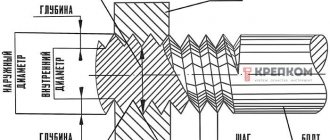
The structural difference between an inch thread and a metric thread is that the ridges are sharper: they are located at an angle of 55° to each other, while for a metric thread the angle between the ridges is 60°.
Thanks to sharper ridge angles, inch threads provide improved connection quality. Due to this, the interface unit can better withstand variable loads and high pressure, which is of great importance when installing pipelines. In some cases, inch threads are used in the manufacture of screws, bolts and other hardware, in the production of parts for certain types of equipment (for example, they are widely used in cameras).
To determine the parameters of different types of threads, different units of measurement are used. Metric uses millimeters and inches uses inches. Inch thread sizes are indicated in fractional and integer numbers. The pitch of an inch thread in tables can be indicated in threads - the number of turns cut into one inch of length.
You can determine the corresponding main dimensions of metric and inch threads of different types using special tables. An example of such a table:
Tightening of threaded connections
To ensure the required strength and integrity of the fasteners, it will be necessary to ensure that the tightening torque corresponds to the value indicated in the table:
| Thread size, inches | Tightening torque for standard bolts and nuts | |
| N*m* | Pound-force foot | |
| 1/4 | 12± 3 | 9±2 |
| 5/16 | 25 ± 6 | 18± 4,5 |
| 3/8 | 47± 9 | 35 ± 7 |
| 7/16 | 70± 15 | 50± 11 |
| 1/2 | 105± 20 | 75±15 |
| 9/16 | 160 ± 30 | 120± 20 |
| 5/8 | 215± 40 | 160 ± 30 |
| 3/4 | 370 ± 50 | 275 ± 37 |
| 7/8 | 620± 80 | 460 ± 60 |
| 1 | 900 ± 100 | 660 ± 75 |
| 11/8 | 1300 ± 150 | 950 ± 100 |
| 1 1/4 | 1800 ±200 | 1325 ±150 |
| 1 3/8 | 2400 ± 300 | 1800 ± 225 |
| 1 1/2 | 3100 ± 350 | 2300 ± 250 |
This table applies only to bolts and nuts with a strength class higher than 5.
How to determine the thread pitch
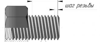
This parameter indicates the distance between two adjacent threads or channels of a threaded connection. Universal options have a standard thread pitch indicated in specialized tables, which makes it easy to select the desired type of fastener.
You can measure the thread pitch yourself in several ways. The simplest one is to select a bolt or nut with a known pitch that fits the thread perfectly. In this case, the pitch of both cuts will be the same.
For the second option, you will need a ruler or caliper with an inch scale. The scale is applied to the thread and the number of threads per inch is calculated. For example, if there are 16 turns in one inch along the ruler, then the thread pitch in inches will be 1/16.
Basic rules for slicing
- To correctly cut inch or metric threads, you must adhere to the following recommendations:
- Accurately select a drill of the required diameter. The hole diameters for UNF and UNC threads are shown in the tables above.
- Drill a hole strictly at right angles to the plane.
- Carry out cutting in a reciprocating motion. After two forward revolutions, make a backward revolution to remove chips.
- If there are two or three taps in the set, pass strictly by numbers - first with the first draft number, then with the second.
- It is advisable to use a lubricant to reduce friction.
Accuracy classes and marking rules
A thread belonging to the inch type, as indicated by GOST, can correspond to one of three accuracy classes - 1, 2 and 3. Next to the number indicating the accuracy class, put the letters “A” (external) or “B” (internal). The full designations of thread accuracy classes, depending on its type, look like 1A, 2A and 3A (for external) and 1B, 2B and 3B (for internal). It should be borne in mind that class 1 corresponds to the coarsest threads, and class 3 corresponds to the most precise threads, the dimensions of which are subject to very stringent requirements.
Maximum size deviations according to GOST
To understand what parameters a specific threaded element corresponds to, it is enough to understand the designation of the thread that is applied to it. The designation in question is used by many foreign manufacturers who work according to American standards relating to elements of threaded connections.
An example of a symbol for an inch thread
This marking contains the following information about the thread:
- nominal size (outer diameter) – first digits;
- number of turns per inch of length;
- group;
- accuracy class.
If you have a question, how to determine the type and size of thread Connecting fittings for pipes and hoses
connections use the table below.
Please note the following:
- connections with inch threads are highlighted in color
- next to the inch step size in tpi the step size in mm is indicated
- connections with external tapered threads usually do not have a threaded groove
- BSPT and NPT conical fittings are very similar, but BSPT has a mark on the hexagon
An important note - situations are quite possible when the inch and metric pitches are very close in size (this is possible on JIC connections).
Read also: Scraper conveyor operating principle
In this case, it is possible to confuse the inch thread. American cylindrical inch thread UNF (Unified Thread Standard)
UNC UNF and metric threads.
Threaded fasteners are one of the most popular for attaching parts, assembling products, equipment, and structures. There is no industry where it is not used. There are many thread characteristics: pitch, tolerance range, number of starts, nominal diameter, profile type and others. One of these is units of measurement, inches or millimeters.
There is often a situation when it is necessary to replace a bolt, pin or screw, but the fastener purchased for maximum similarity “by eye” is not screwed into the mounting hole. One of the reasons is an attempt to screw a fastener with an external inch thread into a hole with a metric thread. Or vice versa. This situation often arises when replacing fasteners on products or equipment manufactured in the UK, USA, Japan, or Australia. There, inch threads have priority.
How to distinguish an inch thread from a metric thread? There are two main ways - by measuring the pitch and diameter or using a special tool.
Measurement
Fastener thread markings are done differently in metric and inch systems. In metric, this is an indication of the thread pitch (the distance between adjacent threads) in millimeters, while in inch it is the number of threads per inch.
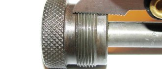
Determining the type and size of fastener thread comes down to the following operations. Use a caliper to measure the diameter. Then, using an inch ruler or caliper, measure the number of threads in one inch and the thread pitch. You can also use a regular ruler with measured 2.54 mm (1 inch = 2.54 mm). The metric thread pitch on small fasteners can be found by measuring the distance between 10 turns and dividing the resulting value by 10. The resulting values should be compared with the table below. The maximum match in diameter, number of turns, pitch indicates the size and type of thread. It should be noted that there are many different types of inch threads. The table shows the most common ones in the diameter range from 8 mm to 64 mm.
You can also use a thread gauge to measure threads. This is its direct purpose. A thread gauge is a set of plates with protruding teeth for a specific thread, united on a single axis. The thread size is engraved or permanently inked on the plate itself. Checking the thread is done by applying plates that are closest in size to the thread. If there is a complete match, without gaps, the thread can be considered defined, and its size can be viewed on the thread gauge plate. Thread gauges are produced separately for metric, inch threads or both types.
