UNC (Unified National Coarse) inch thread is a national American thread with a large pitch and a profile angle of 60°. This thread is a modification of the 55° BSW (British Standard Witworth) thread, also known as a Whitworth thread. Inch threads are based on the inch measurement system, while in Russia the metric system is adopted, for this reason many questions arise related to the definition and search for such fasteners on the Russian market. UNC inch thread is common in the USA, Canada, and Great Britain. UNC thread geometry and form are regulated by ASME B1.1-2003 (The American Society of Mechanical Engineers).
A distinctive feature of inch threads is the designation of diameter and length in fractions of an inch. The English inch is used as a basis, equal to 25.4 mm. Such sizes are indicated by inch, in or double stroke “. In this case, the size will be indicated in fractions of an inch, for example 1″ or ½”. The thread pitch of an inch fastener refers to the number of threads in a 1-inch piece, for example 1″ - 8 UNC. In this case, the number of threads per inch may not be indicated, since in the UNC thread standard, each thread diameter has a certain number of turns. Then the thread designation could be 1″ UNC. Small thread diameters, less than 1/4″, are designated by a conventional number from 0 to 12 and the symbol No. or # is added, for example # 4 - 40 UNC.
Thread Features
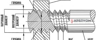
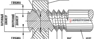
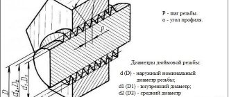
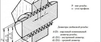
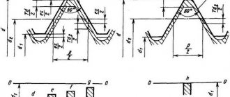
The UNF/UNC inch thread is right-handed and has a tip angle of 60°. UNC is a thread with a coarse pitch, UNF is a thread with a fine pitch. Basic thread parameters:
- d (D) – outer diameter;
- dp (Dp) – average thread diameter;
- di (Di) – internal diameter;
- n – pitch or number of threads per inch.
Diameters and other thread parameters are presented in the tables below.
Coarse UNC thread
UNF fine thread
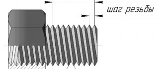
One of the main differences from metric is the determination of the thread pitch. At UNF/UNC. as in other inch standards, the pitch is equal to the number of turns per inch, and not the distance between turns as in metric. The standard provides two thread forms - with a flat recess (UN) and a radius recess (UNR), and three accuracy classes - 1A, 2A, 3A, 1B, 2B, 3B. Taps are produced for accuracy classes 1B, 2B, 3B, which relate to internal threads. Class 1B is the roughest and is used for quick assembly even with partially broken turns. Class 2B is a general purpose thread, 3B is the most stringent standard with minimal clearance in the connection.
How to determine the weight of a pipe
There are several ways to find out the mass of a pipe. The easiest and fastest method is to use a directory or get information on a thematic website. The profile tables indicate the calculated weight of 1 linear meter. for various sizes.
There are sites on the Internet where you can calculate the weight of a pipe using an online calculator. To do this, you need to know the wall thickness, internal or external diameter. Another option is to calculate the weight using the formula. This formula is prescribed in document GOST No. 8732. It is suitable for calculating the mass of pipes of any type. Therefore, the data obtained from such calculations will only be approximate. But in most cases there is no need to obtain the most accurate mass. In addition, the indicators obtained as a result of calculations using the formula are within the permissible error. Therefore, you can operate with such values.
Tool design
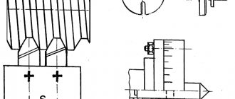
The UNF/UNC tap is a screw with flutes and corresponding sharpening of the front, back and other corners. The main elements of the tool are the cutting (taking) and calibrating parts, grooves for removing chips. The cutting part is made of high-speed steel or hard alloy. A suitable shank is available for manual use or installation in a chuck.
The advantage of the tool is the simplicity and manufacturability of the design, as well as high cutting accuracy and the ability to work due to self-feeding. The difficulty is the need to apply large cutting forces and friction forces, and difficulties in removing chips.
Depending on the design, UNF/UNC taps are divided into:
- manual or metalworking;
- machine-manual;
- machine;
- nuts and others.
Slicing technology
The creation of NPT is carried out using threading machines equipped with a specialized tool, represented by a tap. It is mounted on a rotating spindle. The object being processed is fixed on the work surface. The process under consideration includes several stages.
- First of all, set the speed and direction of rotation of the spindle assembly.
- Next, install a tap of the appropriate size, securing the head with a supporting special clamp.
- Work begins with the fact that after starting the equipment, the head is brought to the workpiece using the control handle.
Cutting occurs automatically. Upon completion of the work, the caliper is raised and the drive is turned off (with the corresponding specified operating pattern). After this, the accuracy of the thread is checked and adjusted if necessary.
Basic rules for slicing
- To correctly cut inch or metric threads, you must adhere to the following recommendations:
- Accurately select a drill of the required diameter. The hole diameters for UNF and UNC threads are shown in the tables above.
- Drill a hole strictly at right angles to the plane.
- Carry out cutting in a reciprocating motion. After two forward revolutions, make a backward revolution to remove chips.
- If there are two or three taps in the set, pass strictly by numbers - first with the first draft number, then with the second.
- It is advisable to use a lubricant to reduce friction.
Can you supply inch fasteners with small diameters?
These dimensions start from #1 (1.854 mm)
up to
#12 (5.436mm)
the TK Hardware company can supply for you to order.
The lead time for these items will be approximately 4-6 weeks
.
The average minimum packaging for such diameters is 200 pieces.
Fasteners with small diameters can be presented in the form of screws with a semicircular head (the so-called computer screws with inch threads), with a countersunk head, with a cylindrical head, in the form of bolts with a hexagonal head, as well as nuts and washers for them. The material in which they can be made is from black (without coating or black) to non-ferrous and stainless metal.
Basic parameters of American inch thread
In technology, mechanical engineering, and construction, large American UNC threads are used, small ones are marked UNF, and also very small ones of the UNEF standard. They differ in the number of turns or threads per inch. Among the main parameters characterizing these threads are:
- The apex angle is 60 degrees, which corresponds to a similar indicator for a metric thread.
- The number of turns per 1 inch TPI, which is offered as 1”/ TPI in a metric thread, this value corresponds to a pitch measured in millimeters.
- The outer diameter is the farthest distance between the tops of threaded ridges lying opposite each other.
- Inner diameter is the same distance between the threads.
- Direction - the thread can twist to the right or left.
- Profile - the difference between the outer and inner diameters indicates the height of the coil.
- Shape - American inch threads can be conical or cylindrical.
For convenience in work, it is necessary to convert the parameters of inch threads into metric units. A summary table of sizes for each type of thread will help with this.
UNC
| Thread size | Threads per inch | D – outer diameter | Dp – average diameter | Di – internal diameter | Thread pitch, mm | |
| inches | mm | millimeters | ||||
| #1 | 1,85 | 64 | 1,85 | 1,6 | 1,42 | 0,40 |
| #2 | 2,18 | 56 | 2,18 | 1,89 | 1,69 | 0,45 |
| #3 | 2,51 | 48 | 2,51 | 2,17 | 1,94 | 0,53 |
| #4 | 2,84 | 40 | 2,84 | 2,43 | 2,16 | 0,64 |
| #5 | 3,17 | 40 | 3,18 | 2,76 | 2,49 | 0,64 |
| #6 | 3,50 | 32 | 3,51 | 2,99 | 2,65 | 0,79 |
| #8 | 4,16 | 32 | 4,17 | 3,65 | 3,31 | 0,79 |
| #10 | 4,83 | 24 | 4,83 | 4,14 | 3,68 | 1,06 |
| #12 | 5,49 | 24 | 5,49 | 4,8 | 4,34 | 1,06 |
| 1/4 | 6,35 | 20 | 6,35 | 5,52 | 4,98 | 1,27 |
| 5/16 | 7,94 | 18 | 7,94 | 7,02 | 6,41 | 1,41 |
| 3/8 | 9,53 | 16 | 9,53 | 8,49 | 7,81 | 1,59 |
| 7/16 | 11,1 | 14 | 11,11 | 9,93 | 9,15 | 1,81 |
| 1/2 | 12,7 | 13 | 12,70 | 11,43 | 10,58 | 1,95 |
| 9/16 | 14,3 | 12 | 14,29 | 12,91 | 12,00 | 2,12 |
| 5/8 | 15,9 | 11 | 15,88 | 14,38 | 13,38 | 2,31 |
| 3/4 | 19,1 | 10 | 19,05 | 17,40 | 16,30 | 2,54 |
| 7/8 | 22,2 | 9 | 22,23 | 20,39 | 19,17 | 2,82 |
| 1 | 25,4 | 8 | 25,40 | 23,34 | 21,96 | 3,18 |
| 1 1/8 | 28,6 | 7 | 28,58 | 26,22 | 24,65 | 3,63 |
| 1 1/4 | 31,8 | 7 | 31,75 | 29,39 | 27,82 | 3,63 |
| 1 3/8 | 34,9 | 6 | 36,93 | 32,17 | 30,34 | 4,23 |
| 1 1/2 | 38,1 | 5 | 38,10 | 35,35 | 33,52 | 4,23 |
| 1 3/4 | 44,4 | 5 | 44,45 | 41,15 | 38,95 | 5,08 |
| 2 | 50,8 | 4 1/2 | 50,80 | 47,13 | 44,69 | 5,64 |
| 2 1/4 | 57,1 | 4 1/2 | 57,15 | 53,48 | 51,04 | 5,64 |
| 2 1/2 | 63,5 | 4 | 63,50 | 59,38 | 56,63 | 6,35 |
| 2 3/4 | 69,9 | 4 | 69,85 | 65,73 | 62,98 | 6,35 |
| 3 | 76,2 | 4 | 76,20 | 72,08 | 69,33 | 6,35 |
| 3 1/4 | 82,5 | 4 | 82,55 | 78,43 | 75,68 | 6,35 |
| 3 1/2 | 88,9 | 4 | 88,9 | 84,78 | 75,68 | 6,35 |
| 3 3/4 | 95,2 | 4 | 95,25 | 91,13 | 88,38 | 6,35 |
| 4 | 101,6 | 4 | 101,60 | 97,48 | 94,73 | 6,35 |
UNF
| Thread size | Threads per inch | D – outer diameter | Dp – average diameter | Di – internal diameter | Thread pitch | |
| inches | mm | millimeters | ||||
| #0 | 1,52 | 80 | 1,52 | 1,32 | 1,18 | 0,32 |
| #1 | 1,85 | 72 | 1,85 | 1,63 | 1,47 | 0,35 |
| #2 | 2,18 | 64 | 2,18 | 1,93 | 1,76 | 0,40 |
| #3 | 2,51 | 56 | 2,51 | 2,22 | 2,02 | 0,45 |
| #4 | 2,84 | 48 | 2,84 | 2,50 | 2,27 | 0,53 |
| #5 | 3,17 | 44 | 3,18 | 2,80 | 2,55 | 0,58 |
| #6 | 3,51 | 40 | 3,51 | 3,09 | 2,82 | 0,63 |
| #8 | 4,17 | 36 | 4,17 | 3,71 | 3,4 | 0,71 |
| #10 | 4,83 | 32 | 4,83 | 4,31 | 3,88 | 0,79 |
| #12 | 5,49 | 28 | 5,49 | 4,90 | 4,40 | 0,91 |
| 1/4 | 6,35 | 28 | 6,35 | 5,76 | 5,37 | 0,91 |
| 5/16 | 7,94 | 24 | 7,94 | 7,25 | 6,79 | 1,06 |
| 3/8 | 9,53 | 24 | 9,53 | 8,84 | 8,38 | 1,06 |
| 7/16 | 11,1 | 20 | 11,11 | 10,29 | 9,74 | 1,27 |
| 1/2 | 12,7 | 20 | 12,70 | 11,87 | 11,33 | 1,27 |
| 9/16 | 14,3 | 18 | 14,29 | 13,37 | 12,76 | 1,41 |
| 5/8 | 15,9 | 18 | 15,88 | 14,96 | 14,35 | 1,41 |
| 3/4 | 19,1 | 16 | 19,05 | 18,02 | 17,33 | 1,59 |
| 7/8 | 22,2 | 14 | 22,23 | 21,05 | 20,26 | 1,81 |
| 1 | 25,4 | 12 | 25,40 | 24,03 | 23,11 | 2,12 |
| 1 1/8 | 28,6 | 12 | 28,58 | 27,20 | 26,28 | 2,12 |
| 1 1/4 | 31,8 | 12 | 31,75 | 30,38 | 29,46 | 2,12 |
| 1 3/8 | 34,9 | 12 | 34,93 | 33,55 | 32,63 | 2,12 |
| 1 1/2 | 38,1 | 12 | 38,10 | 36,73 | 35,81 | 2,12 |
UNEF
| Thread size | Threads per inch | D – outer diameter | Dp – average diameter | Di – internal diameter | Thread pitch | |
| inches | mm | millimeters | ||||
| #12 | 5,49 | 32 | 5,49 | 4,97 | 4,63 | 0,79 |
| 1/4 | 6,35 | 32 | 6,35 | 5,83 | 5,49 | 0,79 |
| 5/16 | 7,94 | 32 | 7,94 | 7,42 | 7,08 | 0,79 |
| 3/8 | 9,53 | 32 | 9,53 | 9,01 | 8,67 | 0,79 |
| 7/16 | 11,1 | 28 | 11,11 | 10,52 | 10,13 | 0,91 |
| 1/2 | 12,7 | 28 | 12,70 | 12,11 | 11,72 | 0,91 |
| 9/16 | 14,3 | 24 | 14,29 | 13,60 | 13,14 | 1,06 |
| 5/8 | 15,9 | 24 | 15,88 | 15,19 | 14,73 | 1,06 |
| 11/16 | 17,5 | 24 | 17,46 | 16,77 | 16,32 | 1,06 |
| 3/4 | 19,1 | 20 | 19,05 | 18,22 | 17,68 | 1,27 |
| 13/16 | 20,6 | 20 | 20,64 | 19,81 | 19,26 | 1,27 |
| 7/8 | 22,2 | 20 | 22,23 | 21,40 | 20,85 | 1,27 |
| 15/16 | 23,8 | 20 | 23,81 | 22,99 | 22,44 | 1,27 |
| 7/16 | 11,1 | 20 | 11,11 | 10,29 | 9,74 | 1,27 |
| 1 | 25,4 | 20 | 25,40 | 24,57 | 24,03 | 1,27 |
| 1 1/16 | 26,9 | 18 | 26,99 | 26,07 | 25,46 | 1,41 |
| 1 1/8 | 28,6 | 18 | 28,58 | 27,66 | 27,05 | 1,41 |
| 1 3/16 | 30,2 | 18 | 30,16 | 29,25 | 28,64 | 1,41 |
| 1 1/4 | 31,8 | 18 | 31,75 | 30,83 | 30,22 | 1,41 |
| 1 5/16 | 33,3 | 18 | 33,40 | 32,42 | 31,81 | 1,41 |
| 1 3/8 | 34,9 | 18 | 34,93 | 34,01 | 33,40 | 1,41 |
| 1 7/16 | 36,5 | 18 | 36,51 | 35,60 | 34,99 | 1,41 |
| 1 1/2 | 38,1 | 18 | 38,10 | 37,18 | 36,57 | 1,41 |
| 1 9/16 | 39,7 | 18 | 39,69 | 38,77 | 38,16 | 1,41 |
| 1 5/8 | 41,3 | 18 | 41,27 | 40,36 | 39,75 | 1,41 |
| 1 11/16 | 42,9 | 18 | 42,86 | 41,95 | 41,34 | 1,41 |
If the thread diameter is less than 1/4 inch, then this size is indicated by numbers in the range from 0 to 12, preceded by the symbol # or No. Each inch thread diameter corresponds to its value in millimeters from the table.
Slicing methods
Inch threads can be applied to almost any cylindrical or conical parts. These could be pipes, bolts, special workpieces, and so on. Basic cutting methods:
- Hand cutting. With this processing method, cutting is carried out using a tap or die. The main advantage of the technology is the high mobility of the technique. The worker does not need to carry the workpiece to the cutting workshop - he can take with him all the necessary tools to perform the cutting on site. For cutting, it is recommended to fix the workpiece in a vice. Then you need to put a die on the end of the pipe or insert a tap into the inside of the pipe. After this, you need to turn the tool to create internal or external threads on the part. To make the job easier, it is recommended to use pliers or similar equipment. If necessary, manual cutting can be done in several passes (this will increase the quality of processing).
- Application of lathes. In this case, processing is carried out using a tapping cutter, which can be used to create external or internal threads. The machines are usually large in size and electrically powered, which makes them not very mobile. For cutting, the workpiece is fixed in the machine chuck, and the cutter is inserted into the support. After turning on the machine, the part is cut, and with the help of the caliper the speed of work and the direction of feed of the cutter are adjusted. Modern lathes can be equipped with a CNC panel, which allows you to automate a number of procedures and simplify the task for the worker.
Each technology has its own pros and cons. Manual cutting is recommended for use in case of a small number of parts (home production or small workshop). Lathe cutting is suitable for large or medium-sized industries with high production load. Before carrying out work, it is necessary to evaluate the parameters of the product (thickness, rigidity, dimensions). In the case of large large-sized parts, a machine-tool processing method is recommended, since manual cutting may be impossible for objective reasons (the worker will get tired quickly, which will reduce the cutting speed).
Making threads
The procedure and rules for cutting it according to the American UNF standard do not differ from the cutting method using the metric system. The only difference is the use of special tools and methods for setting up the machine. As for metric connections, manual or mechanical thread cutting is used. Both methods are applicable for cutting internal and external threads.
The basic rules that must be followed when cutting are:
- selection of the required drill diameter;
- preliminary selection of diameter (it must be equal to the diameter minus the pitch).
These data are provided in reference tables. If such tables are missing, the calculation must be done independently.
At enterprises engaged in the mass production of parts that use inch American cylindrical threads of this standard, mechanical cutting methods are used. This operation is performed using the following equipment:
- lathes equipped with special taps;
- threading machines capable of producing external and internal cutting;
- screw-cutting lathes equipped with numerical control.
The third type of machines is equipped with special programs that allow you to cut the entire list of UNF.
Tightening torques
Tightening torques for UNC inch fasteners for SAE grade 5 and higher bolts and nuts are shown in the following table.
| Thread size, inches | Tightening torque for standard bolts and nuts | |
| N*m* | Pound-force-foot** | |
| 1/4 | 12± 3 | 9±2 |
| 5/16 | 25 ± 6 | 18± 4,5 |
| 3/8 | 47± 9 | 35 ± 7 |
| 7/16 | 70± 15 | 50± 11 |
| 1/2 | 105± 20 | 75±15 |
| 9/16 | 160 ± 30 | 120± 20 |
| 5/8 | 215± 40 | 160 ± 30 |
| 3/4 | 370 ± 50 | 275 ± 37 |
| 7/8 | 620± 80 | 460 ± 60 |
| 1 | 900 ± 100 | 660 ± 75 |
| 11/8 | 1300 ± 150 | 950 ± 100 |
| 1 1/4 | 1800 ±200 | 1325 ±150 |
| 1 3/8 | 2400 ± 300 | 1800 ± 225 |
| 1 1/2 | 3100 ± 350 | 2300 ± 250 |
*1 Newton meter (N*m) is equal to approximately 0.1 kgm.** Pound-force foot is the British and US equivalent of N*m.
Production: video
We have already talked about two cutting methods. Now let’s take a look at one of them, which you can do yourself at home:
In the article we wrote about conical and cylindrical inch threads. We provided tables, as well as calculation methods, talked about the features (parameters) of choice, and even gave a short historical summary. We hope this information was useful to you. To conclude, there is a video:
After you read the article, you can read about our products. for 15 years on the Russian market. During this time, we covered almost all cities of the country.
Application of UNF thread
Cylindrical inch threads, which include UNF and BSW, have a fine pitch. Therefore, they are used for various fastening structures that are subject to increased connection requirements. This fine pitch thread is used in two types of connections:
- high strength;
- regulatory.
Possessing an inch thread measuring one quarter and one and a half inches (according to the American standard), it is used in the following units and structures:
- various types of pipe connections (inch, calibrated, plumbing, gas);
- hydraulic structures (fittings, adapter taps);
- thread adapters;
- union nuts;
- bolts and nuts for fastening structures of various units.
Its versatility and good reliability make it possible to use the American design in mechanical engineering and in the production of machine tools, equipment and tools.
What are inch taps and inch threads?
A tap is perhaps the most common tool for cutting internal threads, which is used everywhere. Threads are cut in new products both by machine and by hand, and worn ones are also restored.
Very often, the use of inch taps is associated with the restoration of threads when repairing equipment, since a large amount of equipment used today in our country is produced according to European or American standards.
To understand what inch taps are, you need to understand what the inch thread is for which they are intended.
The concept of inch, in contrast to metric, includes a fairly large number of different threads that have different pitches and profile angles.
Therefore, to select the right tap, you need to know several determining parameters. All inch threads are designated by a diameter in inches (fraction), as well as a pitch in threads (turns) per 1 inch.
And parts or tools are not always marked with the type to which they belong. This is what causes confusion.
First of all, there are 5 standards that specify the parameters of all the most frequently used ones:
- DIN ISO 228 (also DIN 2999, DIN 259 GOST 6357-81) - determines the parameters of cylindrical inch pipe threads. The profile angle is 55°. It has only four pitch values - 11, 14, 19 and 28 threads per inch. Designated G (less commonly Rp), and also corresponds to BSP (British Standard Pipe) threads.
- BS 84 (formerly DIN 11) - defines the parameters of British Standard BSW (Ww) and BSF threads, Whitworth threads and fine pitch threads respectively. The profile angle is 55°.
- ANSI/ASME B 1.1 is an American standard that defines threads of the unified family: UNC, UNF, UN, UNEF, UNS. The profile angle is 60°, the same as the metric one. The most common are UNC and UNF, with coarse and fine pitches respectively. For example, a 1/4" thread with 20 threads per inch is UNC, and a 1/4" thread with 28 threads per inch is UNF. UNEF is a thread with an especially fine pitch.
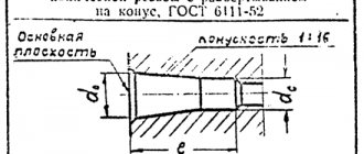
- ANSI B.1.20.1 (also GOST 6111-52) is a standard for tapered pipe threads, which in the American standard is designated NPT (taper 1:16). The profile angle is 60°. In GOST 6111-52 it is designated by the letter K - conical inch. The American standard also describes cylindrical pipe NPS.
- DIN 40 430 is also a standard for pipe threads, designated PG. It practically never happens here.
As you can see, it is quite easy to get confused in so many designations, so you need to be careful when ordering a tool. If possible, you need to check the thread with a gauge or consult with specialists.
As a rule, for the same diameter in inches, each thread has its own pitch, so you can determine from the catalog what type it is. The most common ones are: G, UNC and UNF.
The rest are quite rare, but they also need to be kept in mind.
NPT/NPTF tapered thread: main characteristics and standards
Appearance of a tapered NPT thread NPT/NPTF (national pipe taper/national pipe tapered fuel) thread is an American standard for tapered pipe threads. This standard applies to pipes and fittings that are manufactured in the USA.
NPT tapered pipe thread complies with GOST 6111-52 “Inch tapered thread with a profile angle of 60 degrees”, which is valid in most CIS countries.
The United States National Hydraulic Transmission Association advises against the use of NPT and NPTF standards in hydraulics. But despite this, the use of these standards is very widespread.
NPT thread diagram
Types of inch threads:
- NPT – thread with a taper of 1:16 and a profile angle of 60°. This thread complies with ANSI B1.21.1, FED-STD-H28/7 standards.
- NPS – cylindrical thread.
- NPTF - sealed inch thread with a profile angle of 60°, sealing occurs due to thread compression. This type of inch thread complies with SAE J476, ANSI B1.20.3, FED-STD-H28/8 standards.
Main parameters of the most common NPTF threaded connections:
| Nominal diameter, inch | Main diameter, mm | Threaded hole, mm | Threads per inch | Pitch, mm |
| NPTF 1/16″ | 7.870 | 6.00 | 27 | 0.940 |
| NPTF 1/8″ | 10.217 | 8.25 | 27 | 0.940 |
| NPTF 1/4″ | 13.577 | 10.70 | 18 | 1.411 |
| NPTF 3/8″ | 17.016 | 14.10 | 18 | 1.411 |
| NPTF 1/2″ | 21.211 | 17.40 | 14 | 1.814 |
| NPTF 3/4″ | 26.566 | 22.60 | 14 | 1.814 |
| NPTF 1″ | 33.195 | 28.50 | 11.5 | 2.209 |
| NPTF 1 1/4″ | 41.952 | 37.00 | 11.5 | 2.209 |
| NPTF 1 1/2″ | 48.021 | 43.50 | 11.5 | 2.209 |
| NPTF 2″ | 60.060 | 55.00 | 11.5 | 2.209 |
| NPTF 2 1/2″ | 72.642 | 65.50 | 8 | 3.175 |
| NPTF 4″ | 113.913 | 107.00 | 8 | 3.175 |
Main parameters of the most common NPT threaded connections:
| Nominal diameter, inch | Main diameter, mm | Threaded hole, mm | Threads per inch | Pitch, mm |
| NPT 1/16″ | 7.870 | 6.00 | 27 | 0.940 |
| NPT 1/8″ | 10.217 | 8.25 | 27 | 0.940 |
| NPT 1/4″ | 13.577 | 10.70 | 18 | 1.411 |
| NPT 3/8″ | 17.016 | 14.10 | 18 | 1.411 |
| NPT 1/2″ | 21.211 | 17.40 | 14 | 1.814 |
| NPT 3/4″ | 26.566 | 22.60 | 14 | 1.814 |
| NPT 1″ | 33.195 | 28.50 | 11.5 | 2.209 |
| NPT 1 1/4″ | 41.952 | 37.00 | 11.5 | 2.209 |
| NPT 1 1/2″ | 48.021 | 43.50 | 11.5 | 2.209 |
| NPT 2″ | 60.060 | 55.00 | 11.5 | 2.209 |
| NPT 2 1/2″ | 72.642 | 65.50 | 8 | 3.175 |
| NPT 4″ | 113.913 | 107.00 | 8 | 3.175 |
| NPT 5″ | 141,300 | 134,384 | 8 | 3.175 |
| NPT 6″ | 168,275 | 161,191 | 8 | 3.175 |
| NPT 8″ | 219,075 | 211,673 | 8 | 3.175 |
| NPT 10″ | 273,050 | 265,311 | 8 | 3.175 |
| NPT 12″ | 323,850 | 315,793 | 8 | 3.175 |
To create an NPT (NPTF) connection, special threading machines with a tap (die or threading head) are used.
ProfInst Stroy brings to your attention equipment with which you can cut NPT (NPTF) threads on pipes and workpieces with high quality:
- Die heads from 1/2 to 2 inches. Designed for high-quality, high-performance thread cutting. Safe and quick replacement.
- Manual threading dies from 1/2 to 1.1/4 inches. Designed for cutting conical pipe threads on water, electrical or gas pipes. It has high performance and is easy to transport.
- Manual threading dies from 1/2 to 2 inches. Can be widely used in equipment installation and construction industry, ideal for increasing labor productivity, reducing construction time, ensuring its quality, and reducing labor intensity.
- Electric threading machines from 1/2 to 2 inches. High-performance threading machine for mobile and stationary use. Suitable for long-term, intensive use in the workshop and on the construction site, used in the installation of heating and water supply systems and in mass production. The machine cuts precise threads of very high quality.
- Electric threading machines from 1/2 to 3 inches. The machine is designed for cutting screw and cylindrical threads on pipes. Used to produce precise, reliable threaded connections on pipes and bolts in accordance with codes. It is designed for long-term industrial use.
- Electric threading machines from 1/2 to 4 inches. The machine is designed for cutting pipe and metric threads. Used for the manufacture of precise, reliable threaded connections on pipes and studs in accordance with standards.
NPT threads are used in connections with increased tightness requirements. Connections with such threads are able to withstand strong pressure of the circulating medium through the pipeline.
To buy equipment for cutting NPT (NPTF) conical threads on pipes, contact ProfInst Stroy managers by contact numbers: +375 (17) 256-22-55, +375 (29) 602-00-80, +375 (29) 766-07-00, we will tell you in detail about the operating features, design and specifics of this type of equipment.
Tapered pipe threads
drawing of pipe tapered threads
Tapered pipe thread GOST 6211-81 (1st standard size)
Parameter Unit: Inch
Fits a rounded 55° straight pipe thread profile. See the top part (I) of the 3D image "drawing of pipe tapered threads".
Symbol
International: R
Japan: PT
UK: BSPT
The letter R and the nominal diameter Dy are indicated. The designation R means external thread, Rc internal, Rp internal cylindrical. By analogy with cylindrical pipe threads, LH is used for left-hand threads.
Examples:
R1 ½ - external pipe thread, nominal diameter Dy = 1 ½ inches.
R1 ½ LH - external pipe thread conical, nominal diameter Dy = 1 ½ inches, left.
Conical inch thread GOST 6111 - 52 (2nd standard size)
Parameter Unit: Inch
Produced on surfaces with a taper of 1:16
Has a profile angle of 60°. See the bottom part (II) of the 3D image "drawing of pipe tapered threads". It is used in pipelines (fuel, water, air) of machines and machines with relatively low pressure. The use of this type of connection assumes tightness and locking of the thread without additional special means (linen threads, yarn with red lead).
Symbol
The first letter is K, then GOST.
Example:K ½ GOST 6111 - 52
It stands for: inch conical thread with an outer and inner diameter in the main plane approximately equal to the outer and inner Ø of a cylindrical pipe thread G ½
Table of main parameters of tapered inch threads
| Thread size designation (d, inches) | Number of threads per 1″ n | Thread pitch S, mm | Thread length, mm | Outer thread diameter in the main plane d, mm | |
| Working l1 | From the end of the pipe to the main plane l2 | ||||
| 1/16 | 27 | 0,941 | 6,5 | 4,064 | 7,895 |
| 1/8 | 27 | 0,941 | 7,0 | 4,572 | 10,272 |
| 1/4 | 18 | 1,411 | 9,5 | 5,080 | 13,572 |
| 3/8 | 18 | 1,411 | 10,5 | 6,096 | 17,055 |
| 1/2 | 14 | 1,814 | 13,5 | 8,128 | 21 793 |
| 3/4 | 14 | 1,814 | 14,0 | 8,611 | 26,568 |
| 1 | 11 1/2 | 2,209 | 17,5 | 10,160 | 33,228 |
| 1 1/4 | 11 1/2 | 2,209 | 18,0 | 10,668 | 41,985 |
| 1 1/2 | 11 1/2 | 2,209 | 18,5 | 10,668 | 48,054 |
| 2 | 11 1/2 | 2,209 | 19,0 | 11,074 | 60,092 |
Pipe cylindrical thread
- The unit of measurement of parameters is inch.
- The direction will be left.
- Accuracy class: Class A in this case is increased, and class B is average.
Why is the measurement done in inches?
Inch sizes came to us from Western manufacturers, since the requirements of the GOST current in the post-Soviet space are formulated on the basis of a special BSW thread (British Standard Whitworth or Whitworth thread). Design engineer Joseph Fittworth (1803−1887) invented and demonstrated the same screw profile for detachable type connections back in 1841, and demonstrated it as completely universal, reliable, and also comfortable to use.
This type of threading is used both in simple pipes and in their elements and connections: locknuts, couplings, elbows, tees.
In the cross-section of the profile, you can see an isosceles triangle with a total angle of 55 degrees and roundings at the tops and in the valleys of the contour themselves, which are used for a higher sealed connection.
Threaded connections should be cut to sizes up to 6. All pipes are created large; for special reliability and to prevent the process of rupture, the pipes in the connections should be fixed with additional welding.
Symbols in the standard.
- International: G.
- Japan: PF.
- England: BSPP.
The letter G indications, as well as the bore diameter, will be given in inches. The outer diameter of the thread itself cannot be found in the designation.
Pipe thread sizes, inch
G ½ - pipes in the form of an external cylinder, the internal diameter of the hole is ½. The outer diameter of such a pipe will be 20.995 mm, the number of steps along the length will be 25.4 mm, which means about 14 steps.
For example:
- G ½ -B—cylindrical pipe thread, internal hole diameter ½ inch, pipe accuracy class coincides with mark B.
- G1 ½ LH-B—cylindrical pipe, internal hole diameter up to ½, accuracy class B, left.
For an internal cylindrical pipe, it is worth using a hole that will fully comply with the parameters.
How to quickly find a pitch in a pipe
You can consider additional photographs from English-language sites that can clearly demonstrate the methodology for using and constructing the structure. Pipe threads are characterized in most cases not by the total size between the tops of the profile, but by the number of total turns per 1 inch along the entire axis of the surface. Using a simple tape measure and a ruler, apply and measure one inch (25.4 mm) and visually calculate the number of steps.
It will be much easier if you have an inch thread gauge in your toolbox. With such a device it is quite easy to carry out all measurements, but it is worth remembering that the threads can differ in the angles of the vertices - 55 and 60 degrees.
Tapered pipe thread GOST 6211081
The unit of measurement for all parameters in this case is inch.
The shape of such a pipe will correspond to the profile of a cylindrical pipe cut with a total angle of 55 degrees Celsius.
Main designations:
- International - R
- Japan - PT.
- UK BSPT.
To do this, it is worth indicating the letter R and the overall nominal diameter Dy. The designation in the form of a letter characterizes the external type of thread, Rc is internal, and Rp is internal cylindrical. In the same way with a cylindrical pipe, LH should be used for left-hand threads.
Examples:
R1 ½ is a tapered cut outer pipe with a nominal diameter of Dy ½ inch.
R1 ½ LH is an outer tapered pipe whose nominal diameter Dy will be ½ inch.
- Inch conical cutting according to GOST 6111−52.
- The unit of measurement in this case is also inches.
- It is manufactured on a surface with a taper of 1:16.
It has a general profile angle of about 60 degrees. It is used in the manufacture of pipelines (water, air, and fuel) for machines and machines with low pressure during operation. The use of this type of connection includes special tightness and locking of the thread without the influence of additional improvised means (linen threads, as well as yarn with red lead).
Main designations
The first letter in the name is K, and after that comes the word GOST.
Example: K: ½ GOST 6111–52.
This inscription is deciphered as follows: an inch conical thread with an outer and inner diameter in the main plane approximately equal to the outer or inner connector of a cylindrical pipe G ½.
Metrically conical cut type. According to GOST 25229 -82.
The unit of measurement this time is mm.
The process of creating a pipe occurs on surfaces with a total taper of 1:16.
Used when connecting pipelines. The angle at the very top of the coil will reach 60. The main plane is shifted when looking at the end.
Slicing principles
When slicing, you need to take into account a number of features:
- cutting accuracy is determined by the parameters of the holes: diameter, perpendicularity of the center line to the surface of the workpiece, length;
- inch is cut with a profile angle of 60 degrees, and metric - 55;
- the tops and bottoms of inch threads, unlike metric threads, have more bluntness and have better tightness;
- to simplify the process, drilling a hole with a cylindrical drill is required; it is selected according to the smallest diameter;
- chamfering is required;
- When working, the tool must be lubricated to prevent overheating;
- when cutting, 2 turns are made forward, and then 1 turn back;
- the force on the cutting tool can be weakened after driving to the middle of the calculated length;
- Once the desired length is reached, the die can be removed by rotating in the opposite direction;
- Before finishing cutting, you need to do a rough cut.
Conical taps are distinguished by an elongated shape of the intake part and an incomplete thread, which additionally plays a calibrating role. In the upper part they have a square cross-section; longitudinal grooves are made on the cutting part to remove chips.
Cutting:
- The workpiece is vertically fixed in a vice.
- Lubricant is applied to the tool.
- The tool is applied perpendicular to the center line for cutting threads, that is, strictly in a horizontal plane.
- Several turns are cut.
- The correctness of the work is checked. In case of misalignment, you need to remove the cutting tool, tap the part and repeat steps 3–4.
- Further cutting is carried out provided that the first turns are correctly positioned. You can check with a regular level.
- A thread is formed to the required length.
- At the end of the work, remove the chips and clean the tool from lubricant.
For cutting on lathes, heads with thread-cutting dies are used. A special design feature of the tool is the automatic spreading of the dies during operation. This ensures high machining precision and optimal productivity.
In some cases, knurling rollers are used. The cutting accuracy is lower than when using heads, and the complexity of the work is higher.
To set up a lathe, it is enough to set the spindle rotation speed to low and associate the caliper offset with it. Setting rule: one revolution of the spindle must correspond to the movement of the caliper by the distance of the thread pitch.
On lathes, adjustments are easy because there are many clutch combinations available on the gearbox. If necessary, it is possible to cut threaded grooves of non-standard sizes.
American thread cutting
The technology for cutting American inch threads does not differ from the production of other types. Manual and automatic methods are used. Manual cutting of inch threads is performed as follows:
- A workpiece of the required diameter is firmly fixed in a vice so that it does not turn during operation, which can lead to damage to the integrity of the thread.
- For external threads, a die of the required diameter is selected, and internal threads are cut with a tap.
- The workpiece is processed with a file, roughness and irregularities are removed from it, and a chamfer is removed so that the workpiece has the correct shape.
- The thread is cut by rotating the tap or die in the desired direction. This must be done without jerking, which could disrupt the integrity of the cutting. You can make several passes to get the desired effect.
Automatic cutting is performed on a lathe using a special cutter. To do this, the workpiece is clamped in the chuck, and its rotation speed is selected from a reference book and depends on several parameters. When cutting using a machine method, you can obtain high-quality threads of a high accuracy class.
You can select the correct diameter of the workpiece or hole to be drilled for the thread using the reference table:
| Size designation | UNC (mm) | UNF (mm) | UNEF (mm) |
| #0 | — | 1,25 | — |
| #1 | 1,5 | 1,55 | — |
| #2 | 1,8 | 1,9 | — |
| #3 | 2,1 | 2,15 | — |
| #4 | 2,35 | 2,4 | — |
| #5 | 2,65 | 2,7 | — |
| #6 | 2,85 | 2,95 | — |
| #8 | 3,5 | 3,5 | — |
| #10 | 4 | 4,1 | — |
| #12 | 4,65 | 4,7 | 4,78 |
| 1/4″ | 5,35 | 5,5 | 5,56 |
| 5/16″ | 6,8 | 6,9 | 7,14 |
| 3/8″ | 8,25 | 8,5 | 8,77 |
| 7/16″ | 9,65 | 9,9 | 10,3 |
| 1/2″ | 11,15 | 11,5 | 11,9 |
| 9/16″ | 12,6 | 12,9 | 13,1 |
| 5/8″ | 14,05 | 14,5 | 14,7 |
| 3/4″ | 17,0 | 17,5 | 17,9 |
| 7/8″ | 20,0 | 20,4 | 21,0 |
| 1″ | 22,85 | 23,25 | 24,2 |
| 1 1/8″ | 25,65 | 26,5 | — |
| 1 1/4″ | 28,85 | 29,5 | — |
| 1 3/8″ | 31,55 | 32,75 | — |
| 1 1/2″ | 34,7 | 36,0 | — |
| 1 3/4″ | 40,40 | — | — |
| 2″ | 46,30 | — | — |
| 2 1/4″ | 52,65 | — | — |
| 2 1/2″ | 58,5 | — | — |
| 2 3/4″ | 64,75 | — | — |
| 3″ | 71,10 | — | — |
| 3 1/4″ | 77,45 | — | — |
| 3 1/2″ | 83,8 | — | — |
| 3 3/4″ | 90,15 | — | — |
| 4″ | 96,5 | — | — |
