Unified inch thread UNF (Unified National Fine) is a national American thread with a fine pitch and a profile angle of 60°. This thread is a modification of the 55° BSW (British Standard Witworth) thread, also known as a Whitworth thread. Inch threads are based on the inch measurement system, while in Russia the metric system is adopted, for this reason many questions arise related to the definition and search for such fasteners on the Russian market. UNF inch thread is common in the USA, Canada, and Great Britain. UNF thread geometry and form are regulated by ASME B1.1-2003 (The American Society of Mechanical Engineers).
A distinctive feature of inch threads is the designation of diameter and length in fractions of an inch. The English inch is used as a basis, equal to 25.4 mm. Such sizes are indicated by inch, in or double stroke “. In this case, the size will be indicated in fractions of an inch, for example 1″ or ½”. The thread pitch of an inch fastener refers to the number of threads on a 1-inch length, for example 1″ - 12 UNF. In this case, the number of threads per inch may not be indicated, since in the UNF thread standard, each thread diameter has a certain number of turns. Then the thread designation could be 1″ UNF. Small thread diameters, less than 1/4″, are designated by a conventional number from 0 to 12 and the symbol No. or # is added, for example # 4 – 48 UNF.
UNC type
The large unified thread of the ASME 1 1 standard has the UNC code. Dimensions interchangeable with previously used NC threads.
| Designation | DN (mm) | DN() | Step | Turns per inch | Dst |
| N1-64 UNC | 1,854 | 0,073 | 0,397 | 64 | 1,5 |
| N2-56 UNC | 2,184 | 0,086 | 0,453 | 56 | 1,8 |
| N3-48 UNC | 2,515 | 0,099 | 0,529 | 48 | 2,1 |
| N4-40 UNC | 2,845 | 0,112 | 0,635 | 40 | 2,35 |
| N5-40 UNC | 3,175 | 0,125 | 2,65 | ||
| N6-32 UNC | 3,505 | 0,138 | 0,794 | 32 | 2,85 |
| N8-32 UNC | 4,166 | 0,164 | 3,5 | ||
| N10-24 UNC | 4,826 | 0,19 | 1,058 | 24 | 4 |
| N12-24 UNC | 5,486 | 0,216 | 4,65 | ||
| ¼”-20 UNC | 6,35 | 0,25 | 1,27 | 20 | 5,35 |
| 5/16”-18 UNC | 7,938 | 0,313 | 1,411 | 18 | 6,8 |
| 3/8”-16 UNC | 9,525 | 0,375 | 1,587 | 16 | 8,25 |
| 7/16”-14 UNC | 11,112 | 0,438 | 1,814 | 14 | 9,65 |
| ½”-13 UNC | 12,7 | 0,5 | 1,954 | 13 | 11,15 |
| 9/16”-12 UNC | 14,288 | 0,563 | 2,117 | 12 | 12,6 |
| 5/8”-11 UNC | 15,875 | 0,625 | 2,309 | 11 | 14,05 |
| ¾”-10 UNC | 19,05 | 0,75 | 2,54 | 10 | 17 |
| 7/8”-9 UNC | 22,225 | 0,875 | 2,822 | 9 | 20 |
| 1”-8 UNC | 25,4 | 1 | 3,175 | 8 | 22,25 |
| 1 1/8”-7 UNC | 28,575 | 1,125 | 3,628 | 7 | 25,65 |
| 1 ¼”-7 UNC | 31,75 | 1,25 | 28,85 | ||
| 1 3/8”-6 UNC | 34,925 | 1,375 | 4,233 | 6 | 31,55 |
| 1 ½”-6 UNC | 38,1 | 1,5 | 34,7 | ||
| 1 ¾”-5 UNC | 44,45 | 1,75 | 5,08 | 5 | 40,4 |
| 2”-4 1/2 UNC | 50,8 | 2 | 5,644 | 4,5 | 46,3 |
| 2 ¼”-4 1/2 UNC | 57,15 | 2,25 | 52,65 | ||
| 2 ½”-4 UNC | 63,5 | 2,5 | 6,35 | 4 | 58,5 |
| 2 ¾”-4 UNC | 69,85 | 2,75 | 64,75 | ||
| 3”-4 UNC | 76,2 | 3 | 71,7 | ||
| 3 ¼”-4 UNC | 82,55 | 3,25 | 77,45 | ||
| 3 ½”-4 UNC | 88,9 | 3,5 | 83,8 | ||
| 3 ¾”-4 UNC | 95,25 | 3,75 | 90,15 | ||
| 4”-4 UNC | 101,6 | 4 | 96,5 |
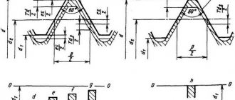
Features of the ANSI ASME B 1 1 UNS thread profile are a 60° isosceles triangle in section and cut tips.
Large threads are characterized by high resistance to jamming and breaking of its turns. Therefore, UNS is considered a threaded profile of general use for all branches of mechanical engineering and construction.
Tightening torques
Tightening torques for UNC inch fasteners for SAE grade 5 and higher bolts and nuts are shown in the following table.
| Thread size, inches | Tightening torque for standard bolts and nuts | |
| N*m* | Pound-force-foot** | |
| 1/4 | 12± 3 | 9±2 |
| 5/16 | 25 ± 6 | 18± 4,5 |
| 3/8 | 47± 9 | 35 ± 7 |
| 7/16 | 70± 15 | 50± 11 |
| 1/2 | 105± 20 | 75±15 |
| 9/16 | 160 ± 30 | 120± 20 |
| 5/8 | 215± 40 | 160 ± 30 |
| 3/4 | 370 ± 50 | 275 ± 37 |
| 7/8 | 620± 80 | 460 ± 60 |
| 1 | 900 ± 100 | 660 ± 75 |
| 11/8 | 1300 ± 150 | 950 ± 100 |
| 1 1/4 | 1800 ±200 | 1325 ±150 |
| 1 3/8 | 2400 ± 300 | 1800 ± 225 |
| 1 1/2 | 3100 ± 350 | 2300 ± 250 |
*1 Newton meter (N*m) is equal to approximately 0.1 kgm. ** Pound-force-foot is the British and American equivalent of N*m.
Type UNEF
The special extra fine thread ANSI ASME B 1 1 for special applications is called UNEF. The dimensions of threaded connections are presented in the table below:
| Standard size | Step | Turns per inch | D drilling | D outer (mm) | D outer (inch) |
| N 12-32 UNEF | 0,794 | 32 | 4,8 | 5,486 | 0,216 |
| 1/4” –32 UNEF | 0,794 | 32 | 5,7 | 6,35 | 0,25 |
| 5/16” – 32 UNEF | 0,794 | 32 | 7,25 | 7,938 | 0,313 |
| 3/8” – 32 UNEF | 0,794 | 32 | 8,85 | 9,525 | 0,375 |
| 7/16” – 28 UNEF | 0,907 | 28 | 10,35 | 11,112 | 0,438 |
| ½” – 28 UNEF | 0,907 | 28 | 11,8 | 12,7 | 0,5 |
| 9/16” – 24 UNEF | 1,058 | 24 | 13,4 | 14,288 | 0,563 |
| 5/8” – 24 UNEF | 1,058 | 24 | 15 | 15,875 | 0,625 |
| 11/16” – 24 UNEF | 1,058 | 24 | 16,6 | 17,462 | 0,688 |
| ¾” – 20 UNEF | 1,27 | 20 | 18 | 19,05 | 0,75 |
| 13/16” – 20 UNEF | 1,27 | 20 | 19,6 | 20,638 | 0,813 |
| 7/8” – 20 UNEF | 1,27 | 20 | 21,15 | 22,225 | 0,875 |
| 15/16” – 20 UNEF | 1,27 | 20 | 22,7 | 23,812 | 0,938 |
| 1” – 20 UNEF | 1.27 | 20 | 24,3 | 25,4 | 1 |
| 1 1/16” – 18 UNEF | 1.411 | 18 | 25,8 | 26,988 | 1,063 |
| 1 1/8” – 18 UNEF | 1.411 | 18 | 27,35 | 28,575 | 1,125 |
| 1 ¼” – 18 UNEF | 1.411 | 18 | 30,55 | 31,75 | 1,25 |
| 1 5/16” – 18 UNEF | 1.411 | 18 | 32,1 | 33,338 | 1,313 |
| 1 3/8” – 18 UNEF | 1.411 | 18 | 33,7 | 34,925 | 1,375 |
| 1 7/16” – 18 UNEF | 1.411 | 18 | 35,3 | 36,512 | 1,438 |
| 1 ½” –18 UNEF | 1.411 | 18 | 36,9 | 38,1 | 1,5 |
| 1 9/16” – 18 UNEF | 1.411 | 18 | 38,55 | 39,688 | 1,563 |
| 1 5/8” – 18 UNEF | 1.411 | 18 | 40,1 | 41,275 | 1,625 |
| 1 11/16” – 18 UNEF | 1.411 | 18 | 41,6 | 42,862 | 1,688 |
The profile is similar to the previous case, all ANSI B 1 1 tables can be downloaded in PDF here. UNEF type threaded connections are used in precision engineering, instrument making, aviation, and shipbuilding.
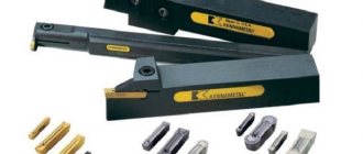
Inch dies for thread cutting UNC, UNF, 8-UN
Warehouse arrivals, promotions, sales!
Complex supplies of tools in small and large wholesale from 3,000 rubles for individuals and legal entities from St. Petersburg across Russia, to Belarus, Kazakhstan in the shortest possible time. Call or submit a request right now! We are updating the catalog. If you have not found the product you need, call back (from 9 to 17:30 Moscow time) or send a request through a convenient form (daily, 24 hours a day).
Inch dies for thread cutting UNC, UNF, 8-UN wholesale
Inch dies (dies) are a cylindrical tool designed for applying external threads to metal products: pipes, rods, rods.
This is a typical standard for America, since it is there that the inch as a unit of measurement is much more common than the centimeter. In Europe and Russia, the inch standard is quite rare.
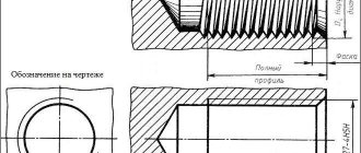
When processing a pipe with a die, the cut inch thread has a conical shape (angle of inclination 60°), the relief is cut off - both the valley and the top.
Inch dies - features of marking and use
An inch die is marked with the letter K. It differs from R-lerks not only in that its diameter is measured not in centimeters, but in inches. Such a thread almost does not cause deformation of the turns. Also, the inch standard differs from the R type models in the wider profile of the threaded “tooth”. In this case, the pitch size is taken to be the number of thread turns per inch.
For the manufacture of blades, only durable material is used - hardened alloy or high-speed steel.
An inch die has a specific classification determined by the thread pitch size.
- Designation UNC - inch dies, allow you to create threads with a wide (large) pitch.
- The designation UNF is an inch standard, indicating that the thread has a fine pitch.
- The UNEF designation is an inch standard used to mark dies that cut threads with particularly fine pitches.
There are also dies marked 8-UN. This designation indicates that the lechers have a single pitch value, regardless of the diameter of the tool. It is 8 threads per 1 inch.
The thread that such a die cuts can be either left-handed or right-handed. It is possible to use both machine and manual pipe processing methods. An inch die is often used for carving non-ferrous metals. It is also used for cutting tool or structural steel.
"Metal Gears" - high-quality tools inexpensively
In the Metal Gears online store you can buy high-quality tools from Russian and foreign manufacturers. We cooperate with American, Asian, European factories and enterprises located in the CIS.
Our company works with manufacturers without intermediaries, therefore we offer goods with a minimal margin. From us you can buy tools wholesale or retail, order specific models or ready-made sets.
And we will contact the manufacturers and ensure prompt delivery of the tool.
For residents of St. Petersburg and the region, goods can be picked up from the warehouse. The remaining regions of the Russian Federation are served through transport or our own courier service “Metal Gears”.
Type UNF
The third table of ASME B 1 1 2003 in Russian shows the dimensions of fine unified threads for general use UNF:
| Standard size | Pitch (mm) | Turns per inch | Drilling D (mm) | D outer (mm) | D outer (inch) |
| N 0-80 UNF | 0,317 | 80 | 1,25 | 1,524 | 0,06 |
| N 1-72 UNF | 0,353 | 72 | 1,55 | 1,854 | 0,073 |
| N 2-64 UNF | 0,397 | 64 | 1,9 | 2,184 | 0,068 |
| N 3-56 UNF | 0,453 | 56 | 2,15 | 2,515 | 0,099 |
| N 4-48 UNF | 0,529 | 48 | 2,4 | 2,845 | 0,112 |
| N 5-44 UNF | 0,577 | 44 | 2,7 | 3,175 | 0,125 |
| N 6-40 UNF | 0,635 | 40 | 2,95 | 3,505 | 0,138 |
| N 8-36 UNF | 0,705 | 36 | 3,5 | 4,166 | 0,164 |
| N 10-32 UNF | 0,794 | 32 | 4,1 | 4,826 | 0,19 |
| N 12-28 UNF | 0,907 | 28 | 4,7 | 5,486 | 0,216 |
| ¼”-28 UNF | 0,907 | 28 | 5,5 | 6,35 | 0,25 |
| 5/16”-24 UNF | 1,058 | 24 | 6,9 | 7,938 | 0,313 |
| 3/8”-24 UNF | 1,058 | 24 | 8,5 | 9,525 | 0,375 |
| 7/16”-20 UNF | 1,27 | 20 | 9,9 | 11,112 | 0,438 |
| ½”-20 UNF | 1,27 | 20 | 11,5 | 12,7 | 0,5 |
| 9/16”-18 UNF | 1,411 | 18 | 12,9 | 14,288 | 0,563 |
| 5/8”-18 UNF | 1,411 | 18 | 14,5 | 15,875 | 0,625 |
| ¾”-16 UNF | 1,587 | 16 | 17,5 | 19,05 | 0,75 |
| 7/8”-14 UNF | 1,814 | 14 | 20,4 | 22,225 | 0,875 |
| 1”-12 UNF | 2,117 | 12 | 23,25 | 25,4 | 1 |
| 1 1/8”-12 UNF | 2,117 | 12 | 26,5 | 28,575 | 1,125 |
| 1 ¼”-12 UNF | 2,117 | 12 | 29,5 | 31,75 | 1,25 |
| 1 3/8”-12 UNF | 2,117 | 12 | 32,75 | 34,925 | 1,375 |
| 1 ½”-12 UNF | 2,117 | 12 | 36 | 38,1 | 1,5 |
An analogue of the UNF thread exists in the UK, and is abbreviated BSW. Fine cylindrical inch thread ensures high connection strength and precise adjustment of the relative position of the parts. Therefore, UNF is often called an adjustment thread, and is used on machine nuts/bolts, threaded adapters, adapter valves, and pipe fittings.
Basic rules for slicing
- To correctly cut inch or metric threads, you must adhere to the following recommendations:
- Accurately select a drill of the required diameter. The hole diameters for UNF and UNC threads are shown in the tables above.
- Drill a hole strictly at right angles to the plane.
- Carry out cutting in a reciprocating motion. After two forward revolutions, make a backward revolution to remove chips.
- If there are two or three taps in the set, pass strictly by numbers - first with the first draft number, then with the second.
- It is advisable to use a lubricant to reduce friction.
Type 8 TPI
Fine unified thread 8 TPI according to ASME B 1 1 specification is developed for special applications, for example, critical parts of wood/metal lathes. The size range corresponds to the following values:
| Standard size | Pitch (mm) | Turns per inch | Drilling D (mm) | D outer (mm) | D outer (inch) |
| 1 1/16”-8 UN | 3,175 | 8 | 23,9 | 26,988 | 1,063 |
| 1 1/8”-8 UN | 3,175 | 8 | 25,5 | 28,575 | 1,125 |
| 1 3/16”-8 UN | 3,175 | 8 | 27,1 | 30,162 | 1,187 |
| 1 1/4”-8 UN | 3,175 | 8 | 28,75 | 31,175 | 1,25 |
| 1 5/16”-8 UN | 3,175 | 8 | 30,3 | 33,338 | 1,313 |
| 1 3/8”-8 UN | 3,175 | 8 | 31,75 | 34,925 | 1,375 |
| 1 1/2”-8 UN | 3,175 | 8 | 35 | 38,1 | 1,5 |
| 1 5/8”-8 UN | 3,175 | 8 | 38 | 41,275 | 1,625 |
| 1 3/4”-8 UN | 3,175 | 8 | 41,5 | 44,45 | 1,75 |
| 1 7/8”-8 UN | 3,175 | 8 | 44,5 | 47,625 | 1,875 |
| 2”-8 UN | 3,175 | 8 | 47,75 | 50,8 | 2 |
| 2 1/8”-8 UN | 3,175 | 8 | 50,9 | 53,975 | 2,125 |
| 2 1/4”-8 UN | 3,175 | 8 | 54 | 57,15 | 2,25 |
| 2 3/8”-8 UN | 3,175 | 8 | 57,2 | 60,325 | 2,375 |
| 2 1/2”-8 UN | 3,175 | 8 | 60,4 | 63,5 | 2,5 |
Weapon parts and fasteners for passenger cars from assembly lines in the USA and Canada often have this thread.
Definition and Description
UNF (Unifed national fine thread) is a cylindrical (parallel) inch thread with a fine pitch according to the American standard ANSI / ASME B1.1.
UNF is a national unified fine thread widely used in the United States and Canada. American threads are represented by two series: UNC - a derivative of the British Whitworth standard with coarse threads comparable to metric ISO threads, and UNF - with fine threads similar to the old SAE (Society of Automotive Engineers of the United States) specification.
Type 12 TPI
The following table ANSI B 1 1 in Russian contains the dimensions of small special threads of the unified type 12TP1:
| Standard size | Pitch (mm) | Turns per inch | D drilling | D outer (mm) | D outer (inches) |
| 1 1/16”-12-UN | 2,117 | 12 | 24,9 | 26,988 | 1,063 |
| 1 3/16”-12-UN | 2,117 | 12 | 28,1 | 30,162 | 1,187 |
| 1 5/16”-12-UN | 2,117 | 12 | 31,3 | 33,338 | 1,312 |
| 1 7/16”-12-UN | 2,117 | 12 | 34,5 | 36,512 | 1,437 |
| 1 5/8”-12-UN | 2,117 | 12 | 39,7 | 41,275 | 1,625 |
| 1 3/4”-12-UN | 2,117 | 12 | 42,4 | 44,45 | 1,75 |
| 1 7/8”-12-UN | 2,117 | 12 | 45,6 | 47,625 | 1,875 |
| 2”-12-UN | 2,117 | 12 | 48,75 | 50,8 | 2 |
| 2 1/8”-12-UN | 2,117 | 12 | 51,9 | 53,975 | 2,125 |
| 2 1/4”-12-UN | 2,117 | 12 | 55,1 | 57,15 | 2,25 |
| 2 3/8”-12-UN | 2,117 | 12 | 58,3 | 60,325 | 2,375 |
| 2 1/2”-12-UN | 2,117 | 12 | 61,5 | 63,5 | 2,5 |
The symbol indicates the outer diameter Dн, pitch TPI and thread type UNC (large), UNF (fine) or UNEF (extra fine). Moreover, for small diameters up to ¼ inch, the integer 0 ... 12 without fractions with the index N or # in front of it is used to indicate the size. Decoding is done using a special table. Since each number corresponds to a specific size.
Tool design
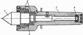
The UNF/UNC tap is a screw with flutes and corresponding sharpening of the front, back and other corners. The main elements of the tool are the cutting (taking) and calibrating parts, grooves for removing chips. The cutting part is made of high-speed steel or hard alloy. A suitable shank is available for manual use or installation in a chuck.
The advantage of the tool is the simplicity and manufacturability of the design, as well as high cutting accuracy and the ability to work due to self-feeding. The difficulty is the need to apply large cutting forces and friction forces, and difficulties in removing chips.
Depending on the design, UNF/UNC taps are divided into:
- manual or metalworking;
- machine-manual;
- machine;
- nuts and others.
Marking
The designation of the thread in question includes a letter indicating the type (UNC) and a digital index indicating the diameter (in inches). In some cases, additional notations are used. They can reflect step (via a dash) and direction. For small options (less than 1/4''), special markings are used. This is due to their difficulty in measuring. Designations include numbers (from 0 to 12) and the frequency of turns (through a dash). For example, you can consider 1/4” – 20UNСх2 1/2”.
- 1/4 – diameter (in this case, the outer value is 6.35 mm, the inner value is 5.35 mm).
- 20 – frequency of turns.
- UNC - typ.
- 2 1/2'' is the length of the bolt.
Production: video
We have already talked about two cutting methods. Now let’s take a look at one of them, which you can do yourself at home:
In the article we wrote about conical and cylindrical inch threads. We provided tables, as well as calculation methods, talked about the features (parameters) of choice, and even gave a short historical summary. We hope this information was useful to you. To conclude, there is a video:
After you read the article, you can read about our products. for 15 years on the Russian market. During this time, we covered almost all cities of the country.
Pipe thread
A separate standard group that regulates the connection of pipes using different wall materials. Inch pipe threads are divided into types:
- cylindrical type;
- conical view;
- NPSM thread.
Straight pipe thread
Also known as Whitward carving. It is used for cylindrical connections using threads and for joining a cylindrical internal thread with an external conical pipe.
The designation of the shape profile is an inch thread with a profile in the form of a triangle with equal hips and an angle at the top of 55º. It is allowed to connect pipes with a maximum diameter of 6 inches, and for pipes larger than an inch size, a connection by welding is used.
Tapered inch pipe thread
It is cut on the surface of pipes for conical connection of pipes and for connecting cylindrical threads on the inside and tapered threads on the outside. The use of sealed gaskets is mandatory; the sealing role is partially played by the thread. The profile is designated as an inch type with a taper; the letter expression of the index indicates its location. R indicates external thread, Rc indicates internal thread, and the letters LH are used for left-hand threads.
Thread profile type NPSM
This thread cutting is done in accordance with American pipe thread standards and is similar in location and type to cylindrical inch threads. Defined by a profile shape in the form of a triangle with an apex of 60º and is produced in sizes from 1/16 to 24 inches.
This type should not be confused with the American subtype NPT, which is a standard inch-threaded conical connection for pipes with increased reliability requirements when working with high pressure and in difficult operating conditions.
Differences between pipe and metric threads
There are not many of them; the most noticeable indicator that distinguishes one type from another is the shape of the threaded ridge cutting profile. In appearance it seems sharper, its apex angle is 55º.
In addition to the profile shape, the difference between metric cutting and the inch pipe version is the measuring parameters of pitch and diameter. Metric threads are measured in millimeters, while imperial threads are measured in inches. But to express metric indicators in inches, a non-standard value of 2.54 cm is used, and a special pipe inch equal to 3.324 cm.
A detailed table indicating the corresponding conversions from inches to millimeters can be found in the specified GOST. In addition to whole inch values, fractional values are also indicated. In addition, the pitch is not counted in millimeters, but in threads, indicating cut grooves on a measured inch segment.
The step is determined using working tools:
- combs;
- calibers;
- mechanical meters.
Measurements are made according to the same rules in metric and inch cutting. To begin with, we use a coupling or fitting with a cut external or internal thread, starting from known parameters. Screw the bolt into the thread and determine the tightness of the fit. If the bolt fits tightly, then the pitch and diameter are considered certain. If the bolt does not match, then try using a bolt of a different caliber.
It is more convenient to use a thread gauge, then the work happens faster - just attach the plate to the thread. The number of the thread is indicated on the tool plate, which is considered defined if the profiles match. A caliper or micrometer is used only to determine the outer and inner diameters.
Designation principles
To determine the main qualities, you need to understand its designation. The thread designation in the drawings is slightly different from those used by the manufacturer in the production of products. Thread tables allow you to determine the main characteristics only by designation.
The features of the marking include the following points:
- Symbol for the thread in question G.
- The diameter size is indicated after the letter. An example of notation is 1 ½.
- The symbol L indicates that the turns are left-handed.
- The next symbol H indicates the accuracy class.
- The make-up length is represented by numbers at the end of the marking.
The designation of a tapered thread in the drawing provides an indication of the accuracy class. A symbol indicating the accuracy class may be indicated in the technical documentation. The creation of turns is carried out in compliance with one of three classes. In addition, the letters “A” and “B” may be indicated next to the number: the first indicates an external indicator, the second internal. The first class corresponds to the coarsest threads, the third is the highest quality.
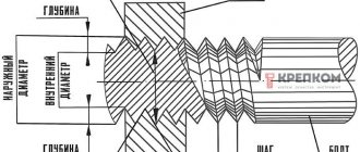
Basic parameters of American inch thread
In technology, mechanical engineering, and construction, large American UNC threads are used, small ones are marked UNF, and also very small ones of the UNEF standard. They differ in the number of turns or threads per inch. Among the main parameters characterizing these threads are:
- The apex angle is 60 degrees, which corresponds to a similar indicator for a metric thread.
- The number of turns per 1 inch TPI, which is offered as 1”/ TPI in a metric thread, this value corresponds to a pitch measured in millimeters.
- The outer diameter is the farthest distance between the tops of threaded ridges lying opposite each other.
- Inner diameter is the same distance between the threads.
- Direction - the thread can twist to the right or left.
- Profile - the difference between the outer and inner diameters indicates the height of the coil.
- Shape - American inch threads can be conical or cylindrical.
For convenience in work, it is necessary to convert the parameters of inch threads into metric units. A summary table of sizes for each type of thread will help with this.
UNC
| Thread size | Threads per inch | D - outer diameter | Dp - average diameter | Di - internal diameter | Thread pitch, mm | |
| inches | mm | millimeters | ||||
| #1 | 1,85 | 64 | 1,85 | 1,6 | 1,42 | 0,40 |
| #2 | 2,18 | 56 | 2,18 | 1,89 | 1,69 | 0,45 |
| #3 | 2,51 | 48 | 2,51 | 2,17 | 1,94 | 0,53 |
| #4 | 2,84 | 40 | 2,84 | 2,43 | 2,16 | 0,64 |
| #5 | 3,17 | 40 | 3,18 | 2,76 | 2,49 | 0,64 |
| #6 | 3,50 | 32 | 3,51 | 2,99 | 2,65 | 0,79 |
| #8 | 4,16 | 32 | 4,17 | 3,65 | 3,31 | 0,79 |
| #10 | 4,83 | 24 | 4,83 | 4,14 | 3,68 | 1,06 |
| #12 | 5,49 | 24 | 5,49 | 4,8 | 4,34 | 1,06 |
| 1/4 | 6,35 | 20 | 6,35 | 5,52 | 4,98 | 1,27 |
| 5/16 | 7,94 | 18 | 7,94 | 7,02 | 6,41 | 1,41 |
| 3/8 | 9,53 | 16 | 9,53 | 8,49 | 7,81 | 1,59 |
| 7/16 | 11,1 | 14 | 11,11 | 9,93 | 9,15 | 1,81 |
| 1/2 | 12,7 | 13 | 12,70 | 11,43 | 10,58 | 1,95 |
| 9/16 | 14,3 | 12 | 14,29 | 12,91 | 12,00 | 2,12 |
| 5/8 | 15,9 | 11 | 15,88 | 14,38 | 13,38 | 2,31 |
| 3/4 | 19,1 | 10 | 19,05 | 17,40 | 16,30 | 2,54 |
| 7/8 | 22,2 | 9 | 22,23 | 20,39 | 19,17 | 2,82 |
| 1 | 25,4 | 8 | 25,40 | 23,34 | 21,96 | 3,18 |
| 1 1/8 | 28,6 | 7 | 28,58 | 26,22 | 24,65 | 3,63 |
| 1 1/4 | 31,8 | 7 | 31,75 | 29,39 | 27,82 | 3,63 |
| 1 3/8 | 34,9 | 6 | 36,93 | 32,17 | 30,34 | 4,23 |
| 1 1/2 | 38,1 | 5 | 38,10 | 35,35 | 33,52 | 4,23 |
| 1 3/4 | 44,4 | 5 | 44,45 | 41,15 | 38,95 | 5,08 |
| 2 | 50,8 | 4 1/2 | 50,80 | 47,13 | 44,69 | 5,64 |
| 2 1/4 | 57,1 | 4 1/2 | 57,15 | 53,48 | 51,04 | 5,64 |
| 2 1/2 | 63,5 | 4 | 63,50 | 59,38 | 56,63 | 6,35 |
| 2 3/4 | 69,9 | 4 | 69,85 | 65,73 | 62,98 | 6,35 |
| 3 | 76,2 | 4 | 76,20 | 72,08 | 69,33 | 6,35 |
| 3 1/4 | 82,5 | 4 | 82,55 | 78,43 | 75,68 | 6,35 |
| 3 1/2 | 88,9 | 4 | 88,9 | 84,78 | 75,68 | 6,35 |
| 3 3/4 | 95,2 | 4 | 95,25 | 91,13 | 88,38 | 6,35 |
| 4 | 101,6 | 4 | 101,60 | 97,48 | 94,73 | 6,35 |
UNF
| Thread size | Threads per inch | D - outer diameter | Dp - average diameter | Di - internal diameter | Thread pitch | |
| inches | mm | millimeters | ||||
| #0 | 1,52 | 80 | 1,52 | 1,32 | 1,18 | 0,32 |
| #1 | 1,85 | 72 | 1,85 | 1,63 | 1,47 | 0,35 |
| #2 | 2,18 | 64 | 2,18 | 1,93 | 1,76 | 0,40 |
| #3 | 2,51 | 56 | 2,51 | 2,22 | 2,02 | 0,45 |
| #4 | 2,84 | 48 | 2,84 | 2,50 | 2,27 | 0,53 |
| #5 | 3,17 | 44 | 3,18 | 2,80 | 2,55 | 0,58 |
| #6 | 3,51 | 40 | 3,51 | 3,09 | 2,82 | 0,63 |
| #8 | 4,17 | 36 | 4,17 | 3,71 | 3,4 | 0,71 |
| #10 | 4,83 | 32 | 4,83 | 4,31 | 3,88 | 0,79 |
| #12 | 5,49 | 28 | 5,49 | 4,90 | 4,40 | 0,91 |
| 1/4 | 6,35 | 28 | 6,35 | 5,76 | 5,37 | 0,91 |
| 5/16 | 7,94 | 24 | 7,94 | 7,25 | 6,79 | 1,06 |
| 3/8 | 9,53 | 24 | 9,53 | 8,84 | 8,38 | 1,06 |
| 7/16 | 11,1 | 20 | 11,11 | 10,29 | 9,74 | 1,27 |
| 1/2 | 12,7 | 20 | 12,70 | 11,87 | 11,33 | 1,27 |
| 9/16 | 14,3 | 18 | 14,29 | 13,37 | 12,76 | 1,41 |
| 5/8 | 15,9 | 18 | 15,88 | 14,96 | 14,35 | 1,41 |
| 3/4 | 19,1 | 16 | 19,05 | 18,02 | 17,33 | 1,59 |
| 7/8 | 22,2 | 14 | 22,23 | 21,05 | 20,26 | 1,81 |
| 1 | 25,4 | 12 | 25,40 | 24,03 | 23,11 | 2,12 |
| 1 1/8 | 28,6 | 12 | 28,58 | 27,20 | 26,28 | 2,12 |
| 1 1/4 | 31,8 | 12 | 31,75 | 30,38 | 29,46 | 2,12 |
| 1 3/8 | 34,9 | 12 | 34,93 | 33,55 | 32,63 | 2,12 |
| 1 1/2 | 38,1 | 12 | 38,10 | 36,73 | 35,81 | 2,12 |
UNEF
| Thread size | Threads per inch | D - outer diameter | Dp - average diameter | Di - internal diameter | Thread pitch | |
| inches | mm | millimeters | ||||
| #12 | 5,49 | 32 | 5,49 | 4,97 | 4,63 | 0,79 |
| 1/4 | 6,35 | 32 | 6,35 | 5,83 | 5,49 | 0,79 |
| 5/16 | 7,94 | 32 | 7,94 | 7,42 | 7,08 | 0,79 |
| 3/8 | 9,53 | 32 | 9,53 | 9,01 | 8,67 | 0,79 |
| 7/16 | 11,1 | 28 | 11,11 | 10,52 | 10,13 | 0,91 |
| 1/2 | 12,7 | 28 | 12,70 | 12,11 | 11,72 | 0,91 |
| 9/16 | 14,3 | 24 | 14,29 | 13,60 | 13,14 | 1,06 |
| 5/8 | 15,9 | 24 | 15,88 | 15,19 | 14,73 | 1,06 |
| 11/16 | 17,5 | 24 | 17,46 | 16,77 | 16,32 | 1,06 |
| 3/4 | 19,1 | 20 | 19,05 | 18,22 | 17,68 | 1,27 |
| 13/16 | 20,6 | 20 | 20,64 | 19,81 | 19,26 | 1,27 |
| 7/8 | 22,2 | 20 | 22,23 | 21,40 | 20,85 | 1,27 |
| 15/16 | 23,8 | 20 | 23,81 | 22,99 | 22,44 | 1,27 |
| 7/16 | 11,1 | 20 | 11,11 | 10,29 | 9,74 | 1,27 |
| 1 | 25,4 | 20 | 25,40 | 24,57 | 24,03 | 1,27 |
| 1 1/16 | 26,9 | 18 | 26,99 | 26,07 | 25,46 | 1,41 |
| 1 1/8 | 28,6 | 18 | 28,58 | 27,66 | 27,05 | 1,41 |
| 1 3/16 | 30,2 | 18 | 30,16 | 29,25 | 28,64 | 1,41 |
| 1 1/4 | 31,8 | 18 | 31,75 | 30,83 | 30,22 | 1,41 |
| 1 5/16 | 33,3 | 18 | 33,40 | 32,42 | 31,81 | 1,41 |
| 1 3/8 | 34,9 | 18 | 34,93 | 34,01 | 33,40 | 1,41 |
| 1 7/16 | 36,5 | 18 | 36,51 | 35,60 | 34,99 | 1,41 |
| 1 1/2 | 38,1 | 18 | 38,10 | 37,18 | 36,57 | 1,41 |
| 1 9/16 | 39,7 | 18 | 39,69 | 38,77 | 38,16 | 1,41 |
| 1 5/8 | 41,3 | 18 | 41,27 | 40,36 | 39,75 | 1,41 |
| 1 11/16 | 42,9 | 18 | 42,86 | 41,95 | 41,34 | 1,41 |
If the thread diameter is less than 1/4 inch, then this size is indicated by numbers in the range from 0 to 12, preceded by the symbol # or No. Each inch thread diameter corresponds to its value in millimeters from the table.
Designation principles
The designation of threads in drawings is carried out according to the following rules.
- Indicate with solid thin and thick lines. The designation of an internal thread is a thin line along the outer diameter and a thick line on the internal one, and an external thread is indicated by a thick line along the outer diameter and a thin line on the internal one.
- If the part is projected onto a plane along the axis of rotation, then it is shown as solid straight lines. If - across, then this is an open contour, 0.75 of the total circumference. The ends of the arc should not lie on the axes of the part in the figure.
- The gap between the thin and thick lines should be more than 0.8 mm, but less than the step size.
- When designating metric threads in drawings perpendicular to the axis, chamfers are depicted only with structural significance.
External and internal thread types
Metric threads are standardized by several documents: GOST 8724-2004, GOST 2470-2004, GOST 9150-2002, GOST 1693-2005. They specify the requirements for dimensions, profile, pitches and tolerances.
Based on the product labeling, you can determine all the necessary parameters and type. Entry includes:
- a capital letter characterizing the type, or two capital letters - a type and a subspecies (for example, metric - M; metric conical - MK);
- a number expressing the nominal diameter in millimeters (M20 - metric with a nominal diameter of 20 mm);
- in the case of a small step, indicate its value in millimeters, using the multiplication sign - M20x1.5;
- in the case of a multi-start, add an indication of the stroke after the “x” and the step in parentheses - M20x3(P1) - metric with a diameter of 20 mm, three-start, where the step is 1 mm;
- when designating a left-hand thread, the Latin capital letters “LH” are written - M20LH or M20x3(P1)LH - also only left-handed.
In some cases, the marking may include additional parameters: make-up length, tolerances and fit. Their decoding is as follows:
- indication of tolerance for external thread M12x1.75-6g and for internal thread M12-6N;
- make-up length is expressed in capital Latin letters - S - shot (short), N - normal (normal), L - long (long), sometimes a numerical value of the length in millimeters is added in parentheses if the value is non-standard; for example, M12-6g-L(30);
- the fit is expressed as a fraction through the tolerance values for internal (numerator) and external (denominator) threads, for example, taking into account how left-hand threads are designated, the general appearance will be M12x1-6H/6g-LH.
The marking may also indicate the type and number of the standard.
By choosing the right type of metric thread and its geometric parameters, you can ensure high-quality fastening of parts, long-term operation of the product and savings on repairs and maintenance.
Accuracy classes and marking rules
A thread belonging to the inch type, as indicated by GOST, can correspond to one of three accuracy classes - 1, 2 and 3. Next to the number indicating the accuracy class, put the letters “A” (external) or “B” (internal). The full designations of thread accuracy classes, depending on its type, look like 1A, 2A and 3A (for external) and 1B, 2B and 3B (for internal). It should be borne in mind that class 1 corresponds to the coarsest threads, and class 3 corresponds to the most precise threads, the dimensions of which are subject to very stringent requirements.
Maximum size deviations according to GOST
To understand what parameters a specific threaded element corresponds to, it is enough to understand the designation of the thread that is applied to it. The designation in question is used by many foreign manufacturers who work according to American standards relating to elements of threaded connections.
An example of a symbol for an inch thread
This marking contains the following information about the thread:
- nominal size (outer diameter) – first digits;
- number of turns per inch of length;
- group;
- accuracy class.
If you have a question, how to determine the type and size of thread Connecting fittings for pipes and hoses
connections use the table below.
Please note the following:
- connections with inch threads are highlighted in color
- next to the inch step size in tpi the step size in mm is indicated
- connections with external tapered threads usually do not have a threaded groove
- BSPT and NPT conical fittings are very similar, but BSPT has a mark on the hexagon
An important note - situations are quite possible when the inch and metric pitches are very close in size (this is possible on JIC connections).
Read also: Scraper conveyor operating principle
In this case, it is possible to confuse the inch thread. American cylindrical inch thread UNF (Unified Thread Standard)
UNC UNF and metric threads.
Threaded fasteners are one of the most popular for attaching parts, assembling products, equipment, and structures. There is no industry where it is not used. There are many thread characteristics: pitch, tolerance range, number of starts, nominal diameter, profile type and others. One of these is units of measurement, inches or millimeters.
There is often a situation when it is necessary to replace a bolt, pin or screw, but the fastener purchased for maximum similarity “by eye” is not screwed into the mounting hole. One of the reasons is an attempt to screw a fastener with an external inch thread into a hole with a metric thread. Or vice versa. This situation often arises when replacing fasteners on products or equipment manufactured in the UK, USA, Japan, or Australia. There, inch threads have priority.
How to distinguish an inch thread from a metric thread? There are two main ways - by measuring the pitch and diameter or using a special tool.
Measurement
Fastener thread markings are done differently in metric and inch systems. In metric, this is an indication of the thread pitch (the distance between adjacent threads) in millimeters, while in inch it is the number of threads per inch.
Determining the type and size of fastener thread comes down to the following operations. Use a caliper to measure the diameter. Then, using an inch ruler or caliper, measure the number of threads in one inch and the thread pitch. You can also use a regular ruler with measured 2.54 mm (1 inch = 2.54 mm). The metric thread pitch on small fasteners can be found by measuring the distance between 10 turns and dividing the resulting value by 10. The resulting values should be compared with the table below. The maximum match in diameter, number of turns, pitch indicates the size and type of thread. It should be noted that there are many different types of inch threads. The table shows the most common ones in the diameter range from 8 mm to 64 mm.
You can also use a thread gauge to measure threads. This is its direct purpose. A thread gauge is a set of plates with protruding teeth for a specific thread, united on a single axis. The thread size is engraved or permanently inked on the plate itself. Checking the thread is done by applying plates that are closest in size to the thread. If there is a complete match, without gaps, the thread can be considered defined, and its size can be viewed on the thread gauge plate. Thread gauges are produced separately for metric, inch threads or both types.
Cutting technology
UNC threads are created by removing a portion of material from the surfaces of cylindrical and tapered workpieces. This is done on machines. Depending on the type, taps and dies are used (for internal and external, respectively).
The shank is used for installation in the driver or chuck of the machine. The working part is divided into intake and calibrating. The first carries out cutting, the second serves for calibration. The cutting edges are formed by longitudinal grooves, which also provide chip exit. The cutting parts limited by grooves are called cutting feathers.
On machine tools, machine options are most often used, however, for hard and viscous materials, specific sets of taps are required, including two or three tools. They differ in the purity of processing and perform different amounts of work. So, for a set of two taps the proportion is 75/25%, for a set of three – 60/30/10%. Structurally, the taps of one set differ in the length of the intake part, which is the longest in the draft version. For workpieces with a surface interrupted by a groove or groove, tools with a number of grooves not a multiple of the number of grooves and with helical grooves are used. The latter are also suitable for holes with a length of two diameters or more. In this case, the direction of the screw groove must correspond to the thread being cut. Specific options are represented by grooveless taps. They are designed to create short through threads. Such tools are more durable and have better quality of work. Another specific version of taps is with staggered teeth, designed for short through threads on tough materials. They reduce friction, improve coolant flow and chip formation. Taps are installed similarly to dies or in cartridges for them. The speed of work is 5-12 for steel and 6-22 m/s for other materials. When cutting, cooling with oil or emulsion is required.
Due to the different configurations on the machines, they are mounted in different holders. Thus, for lerks, lerk holders are used, represented by cranks in the form of frames with 2 handles. The die is located inside and is fixed with three screws that go into the recesses on its sides. The frames for sliding options are made in the form of oblique frames with 2 handles. Half dies are placed in the hole, adjusting the size with a pressure screw.
Before cutting the thread, the surface of the workpiece is treated. For an external connection, it is necessary to ensure a smaller diameter in relation to the outer diameter of the thread. This difference is approximately 0.1-0.3 mm depending on the size of the connection. At the end, a chamfer corresponding to the height of the profile is removed to form an approach. The die is mounted with a holder in the socket of the head or tailstock quill. The speed of work is determined by the type of material. So, for steel blanks it is 3-4, for cast iron - 2-3, for brass - 10-15 m/min.