Installation of any power or lighting network, equipment repair and other electrical work always involves checking the integrity of the circuits. Often, a faulty wiring or any component is the result of a broken switching line, which can be diagnosed by testing the conductors. This article will discuss testing methods, and also discuss in detail the option of diagnosing a circuit using a multimeter.
What is used for wiring
Professional and homemade testers are used to check for broken wires or to detect a short circuit. Self-produced devices are presented in the form of a battery and a light bulb attached to it.
Professional testers are multimeters, with which you can not only test wires, but also perform a number of other diagnostic work on the electrical network.
This is a convenient and easy-to-use device that is always in the electrician’s arsenal.
Causes of emergency mode
The main reason for the occurrence of a short circuit is a sharp increase in current strength, the increase of which occurs in parallel with a decrease in the resistance of the conductors. Under the influence of high current, a critical temperature is created that is dangerous for networks and equipment.
This situation, in turn, is also created due to certain factors:
- Voltage surges when all permissible parameters and nominal values are exceeded. An electrical breakdown of the insulation of the wires or the entire circuit occurs. The current leak instantly turns into a short circuit, forming a stable short-term arc discharge.
- The causes of short circuits often lie in worn-out insulation, especially in old buildings where the electrical wiring has not been changed for a long time. The insulating layer is influenced by external factors, and after its service life is exhausted, it is destroyed. A short circuit occurs at the points of contact between exposed conductors.
- Any types of mechanical impacts that negatively affect the integrity of electrical wiring insulation. The shell gradually loses its qualities and collapses. Wires are often damaged when drilling into walls and lacking electrical wiring diagrams.
- Contact of foreign objects with live parts. They close the contacts, leading to the emergence and development of an emergency mode.
- Direct lightning strikes have the same effect as voltage surges.
- Operation of electrical networks with overloads for a long time, disruptions and malfunctions of electrical equipment are serious causes of short circuits.
- A sharp increase in humidity in the room, for example, due to flooding by neighbors above. Moisture has a destructive effect on the insulation at joints and twists, leading to unplanned contacts between conductors.
How dialing works
The multimeter has its own power source, and with its help voltage is supplied to the de-energized conductor.
Voltage is applied to the conductor through a multimeter.
Every material has a resistance that can be measured or calculated. A multimeter set to the “resistance determination” position is used to test the wire. The display of the device indicates the resistance value of the material.
The current strength I is directly proportional to the voltage U and inversely proportional to the resistance R. Many people remember this formula from physics lessons.
I=U/R
This means that the voltage that is in the multimeter is supplied to the conductor being tested. The material data is analyzed and the result is displayed.
The very fact that it was possible to find this value explains that the conductor is not damaged.
Methods of elimination and prevention
- It is better to replace sockets, power cords and other shorted network elements.
- To eliminate short circuits in electrical appliances, use the services of specialized workshops, or repair them yourself (if you have knowledge and experience).
- Fix a cable break by replacing the damaged section with a new wire. In this case, make sure that the insulation resistance coefficient corresponds to the current value.
For preventive purposes, check the serviceability of the contacts. Change sockets in a timely manner. Use only standard electrical appliances. Do not exceed load levels. Connect only working power tools and other household appliances to the power source.
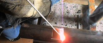
In Fig. Figure 5 shows the consequences of operating an electric generator with a faulty cord.
Figure 5. Short circuit of a faulty cord
Remember that your safety largely depends on the reliability of the electrical supply system for residential and domestic premises. This is one of the few cases where savings are not appropriate.
In what cases is an inspection carried out?
Testing is used when it is necessary to ensure the integrity of the circuit.
There are different cases:
- broken switch or socket;
- failure of household electrical appliances;
- checking printed circuit boards;
- car wiring diagnostics;
- searching for the required core among a large number of other conductors;
- diagnostics of communication lines, as well as lighting and power networks during their installation.
They resort to checking the wires when the socket breaks down.
Checking the wires with a faulty switch or socket should be carried out only after other possible failures have been ruled out.
For example, a broken connection or a defective electrical current receiver.
The causes of damage to wires can be mechanical impact (during repair work) and overloads that cause a short circuit. It can also be determined with a multimeter.
Why does the steering column cable fail?
Despite performing the same function, the designs of steering column cables on cars of different brands can be very different. The internal design features of these elements reflect the direction of thought and the needs of specific automakers. Some models of loops have a very simple design, a small number of signal lines and methods of transmitting control signals. Other models are distinguished by high technology, the use of powdered conductive compounds and a complex system of interaction with control modules.
There are several reasons why steering column cables fail. Firstly, this is aging, which results in abrasion of the conductive layers. As a result, the buttons on the steering wheel stop working (either all at once or gradually). In some car models, the control indicator on the instrument panel lights up! Secondly, damage to the steering column cable may occur as a result of carelessly turning the steering wheel to its extreme position or when repairing the car’s steering column carelessly.
Setting up the multimeter
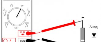
To diagnose the integrity of the wires on the multimeter, you need to set the continuity mode. The measuring device comes with two wires with probes: red and black. They need to be inserted into the corresponding sockets: “COM” - for black, “VωmA” - for red. In this way, polarity is observed when measuring.
To check the serviceability of the tester, the probes of the red and black wires must be connected to each other. A characteristic bell is heard - the multimeter is ready for use.
Indicators and their interpretation
When checking conductors, digital values appear on the tester’s display, which determine the presence of resistance in the conductor.
While checking the conductors, digital values appear.
A signal sounds and the number “0” (or close to zero) is displayed on the screen - the conductor is not damaged.
If there is no sound and the device shows “1”, there is a break in the wire.
Limits of values
If you check the integrity of the conductors in the “resistance determination” mode, then it is necessary to set the limits of the values.
Values entered manually are always multiples of 2. For testing long wires - 20 ohms. The minimum figure that can be specified is 2 ohms.
Connecting the tester
The multimeter, set in the desired mode, is connected with two probes to the contacts of the conductor being tested. For convenience, the probes and ends of the wire are sometimes secured with metal clips - “crocodiles”. The tester immediately displays diagnostic results on the screen.
The image is distorted. Initial diagnosis when image problems occur
Vertical stripes on the laptop screen or horizontal stripes, image output only on part of the screen, ripples on the monitor and other artifacts on the matrix can be caused by:
- matrix malfunction (in this case, only replace the matrix);
- damage to the matrix cable (it is possible to restore damaged contacts);
- burnt video card (in some cases replacement is possible);
- desoldering of the video chip (usually caused by overheating of the laptop);
- damage on the motherboard. (for example, the occurrence of corrosion after flooding).
Initial diagnosis when problems occur with the image:
- We connect an external monitor, if the image on it is normal, then most likely the video card is fine, but not a fact. Floating defects may appear on the motherboard;
- We check the response of the matrix to mechanical stress (bending or torsion). If the image changes when bending or pressing, then the problem is in the matrix itself or its cable;
- Let's see if the image changes when closing and opening the laptop lid, if so, then check the cable coming from the motherboard. There may be poor contact in the cable connector or damage to the tracks.
Let's look at some examples of screen image problems and what causes them:
1. Colored vertical lines on the LCD monitor.
Many colored vertical lines chaotically changing colors. This image looks like the Northern Lights. The external monitor works great though.
With a slight bend the image changed. Horizontal lines appeared in the middle of the display.
In this case, the matrix cable is faulty.
Vertical stripes on the LCD screen.
Vertical stripes of different colors may appear on the monitor once when you turn on the computer.
If you give it a slight bend, the lines on the screen may disappear. And when displaying the image on an external display, everything is fine, no lines. Unfortunately, these stripes on the screen indicate a malfunction of the screen matrix itself and this is not connected with its cable. This fairly typical problem can be solved by replacing the matrix.
Red and blue stripes on the display.
Vertical stripes all over the LCD screen. Sometimes the stripes are red, sometimes they are blue, and may become wider and change color to white.
A similar picture on the external monitor, the same vertical lines. Most likely there is a problem with the video card. On some laptops, the video adapter is integrated into the motherboard, while on other models it is a separate module.
In this case, it is necessary to rebowl or replace the video chip. This requires a special
soldering station for soldering BGA components.
Ripple on the monitor.
Red ripples all over the computer screen. Everything on the external display is clean, the image is excellent. It can be assumed that the matrix or its cable is faulty.
But after replacing the matrix and cable, the monitor began to glow red again. This was due to interruption of contact between the video adapter and the motherboard. It is necessary to rebowl the video chip or replace the motherboard.
Image on half the screen.
The left half of the screen works fine, but the right side is completely white.
The recipe is simple - replacing the matrix.
Bad image.
Here is another laptop with a bad LCD screen. A stripe with ripples on the monitor.
This is a candidate for matrix replacement.
7. Vertical stripes on the laptop screen.
Multi-colored stripes on the display. There are no problems with the image on the external monitor.
If you rotate the screen a little, a distorted image appears with horizontal lines across the entire matrix.
After a few seconds the image becomes blurry.
No option - replacing the matrix.
The monitor changes colors or has a negative image on the screen.
All colors are displayed inverted - white instead of black, black instead of white, yellow instead of red, etc. This laptop shows color inversion right out of the box. As you can see, the Toshiba logo is light green instead of red.
Checking the heating element
Before checking the device, you need to calculate its resistance. This is easy to do if you know the power of the heating element. It is indicated in his documents or on the back of the case.
You can calculate the resistance using the formula:
R=U²/P,
where U is the network voltage, P is the power of the heating element, and R is the resistance.
If the heating element has a power of 2000 W, and the mains voltage is 220 V, then the resistance calculated using this formula is 24.2 Ohms.
Before checking the heating element, its resistance is calculated.
Next you can proceed to the measurement process:
- Before checking the heating element circuit, you need to turn it off from the network and disconnect the wires.
- On the multimeter, set the “resistance measurement” mode and indicate the range up to 200 Ohms.
- Using the probes of the tester, touch the terminals of the heating element. If the device being tested is working properly, the multimeter display displays a number close to what was found using the formula. If the multimeter shows “1”, then there is a break. If “0” there is a short circuit inside the heating element.
In the continuity mode, the heating element can be checked for the presence of a breakdown on the body. To do this, connect one of the tester probes to the terminal of the device, and the second to its body or to ground. If there is a breakdown, the tester will beep.
Repair under the steering loop
Typically, this malfunction first manifests itself gradually. What does it mean? Well, as a rule, periodically the airbag error light comes on on the dashboard and the sound signal disappears. Repairing it will not be difficult for the average owner.
Repairing a cable at a car service center is expensive and time-consuming. And buying a new one is also very expensive, but this option is not excluded. Repairing the old one is quite simple.
The first thing to do is disconnect the airbag and remove the steering wheel. This is different for different cars. But in order for the airbag not to work when dismantling it, you need to remove the terminal from the battery and wait 10-20 minutes for it to discharge. Then disconnect the cable from the airbag. To prevent the cable from unwinding during the repair process, it must be secured with tape. After which it is necessary to detect the places where the contacts are broken. They need to be cleaned and the wires soldered. That's all the work. Then we put everything back together.
Attention! If you doubt your abilities, do not take on this job!
If you liked the article, like and subscribe to the channel. Every day we publish new interesting articles .
Safety when using a multimeter
When working with the tester, you must remember the precautions and follow the safety rules:
- Before testing the circuit with a multimeter, turn off the power to the network.
- Place a warning sign near the switch that is turned off indicating that work is being carried out.
- Do not touch exposed wires with your hands.
- Work in specialized clothing and rubber gloves.
- If there are capacitors in the circuit, they must be discharged. Otherwise, the multimeter will be damaged. During the test, experts recommend:
- use “crocodiles” (these are clips that are attached to the ends of the tester wires; the contact becomes more reliable and your hands are freed);
- Do not touch bare wires or probes with your hands, otherwise the measurements will not be correct.
When using a multimeter, you need to turn off the power.
But if you have doubts about your diagnostic abilities, it is better to trust the specialists.
Start
You will have to suffer a little with the body of the steering column switch block. The required cable is named B5567-JD00A. That's it, let's move from talk to action. The test subject was a 2008 Nissan Qashqai.
The reason for the replacement cannot be considered only as an airbag failure - maybe the cruise control does not respond or the volume control, horn, or SRS are not working well.
From inventory we will need:
- steering wheel slip ring 25567-EB60A;
- key to 10;
- large flat screwdriver – 2 pcs.;
- Phillips analogue of a flat screwdriver;
- head at 19;
- 2 stars – T25 and T10;
- gloves - we will work in them.
How to test wires with a multimeter
To check the wires, you must first turn off the power.
Then:
- bring the multimeter into working condition;
- set the desired mode;
- attach the probes;
- check the readiness of the tester.
After preparation, you can begin checking. Connect the multimeter probes to the bare ends of the wire. There is a signal - the conductor is intact.
Wiring in the apartment
In this case, each room has separate electrical wiring, which is powered through a circuit breaker from the panel.
If there is a power outage in your apartment, the first thing you need to check is the distribution board.
The electrical wiring in the house is powered through a circuit breaker.
If the machines do not turn off, the breakdown most likely lies in the receiver or in the room lamp switch. And if the protection has worked, you need to check all the wiring.
Dialing is allowed only in a de-energized network. Before diagnosing, it is necessary to check whether there is current in the circuit.
The first thing that fails is the outlet itself. You can identify defects in it visually by removing it from the socket. But it is better to perform diagnostics using instruments.
If it is in working order, the junction box is checked. It is located close to the outlet. The box contains twisted conductors: phase, ground and neutral. With one multimeter probe you need to alternately touch the contacts in the socket, and with the other, touch the bare ends of the twists. This is how a damaged conductor is identified.
Circuit continuity check
To test the continuity of the chain, it is necessary to check each element included in it. The multimeter probes must be connected to different ends of one wire, thus short-circuiting it. A sound was heard - everything is in order with the conductor, otherwise replacement is required.
Continuity of a long conductor
There are times when it is necessary to find out whether a wire whose ends are far apart is damaged. Then grounding is used for testing. You need to connect one end of the core being tested to the ground using a metal rod, and use the multimeter probes to touch the other end and the ground wire.
To test a long conductor, you can use grounding.
This results in a closed circuit in which the ground is the conductor.
How to ring a wire in a car
Testing the electronics in a car is carried out in the same way as in other cases: by touching the tester probes to the ends of the conductor. It is important to turn on the engine at idle speed before checking. In the case when only one contact is available for dialing, the second tester probe is placed on ground (the metal body of the car). It performs the function of grounding.
Fuse
This is a device that prevents elements in the circuit from overheating. It looks like a small plate or cylinder with a thin cable inside. To test it, multimeter probes are applied to different sides. In the “continuity” mode, if the fuse is intact, a sound should be heard.
In the “resistance determination” mode on the tester screen: “0” – no break, “1” – conductor damage.
Lamps
When checking, you need to connect one tester probe to the central contact, and the second to the side. Diagnostics also takes place in dialing mode.
Such a check can only be carried out with a screw base.
Diodes and LEDs
In a diode, polarity is determined by the anode and cathode. Therefore, it conducts current in one direction. To check an element, the appropriate mode is set on the tester. The poles of the diode are touched with the probes of a multimeter, and then they are swapped.
If, as a result of one test, the tester showed “0”, and during another “1”, the element is working.
The LED has reverse polarity. When the positive contact touches the anode and the negative contact touches the cathode, it lights up. When the position of the tester wires is changed, the voltage disappears. This determines that the LED is in working condition.
Operating procedure
The sequence of actions is as follows:
- Use the key to disconnect the battery.
- We climb under the steering wheel housing and find 3 bolts. Unscrew it.
- We take a flat-head screwdriver and look at the left and right sides - we see latches there. We disconnect - this will allow you to remove the bottom and top of the casing for convenience. Work slowly, try to move the steering wheel slightly left and right and apply pressure in the process.
In some cases, only the top cover is removed, sometimes the bottom cover is held on by 2 self-tapping screws, they need to be removed with a T25 star.
- We insert both screwdrivers into the resulting holes and get rid of the airbag (first unfasten a couple of connectors).
- Next, use a 19mm socket to unscrew the central nut and remove the steering wheel. A controversial option is to hit hard with your fist.
- Here comes the turn of the steering column switches (deactivate 3 connectors). Pull out the cable. Sometimes you have to manipulate the steering position sensor using T10.
- Unscrew the plastic cover from the sensor - it will move to the new cable. Then we replace the part. After this, you need to remove the plastic retaining clip.
- We reinsert the 3 wires of the pillow (you noticed, one chip is yellow, the other is gray, you need to plug in the yellow one first) and connect the wires back. We get to the stage of installing the pillow without latching it completely - we need to check.
- We leave the car and return the terminal. If there is a mistake, the airbag will fire. If everything is in order, we return to the steering wheel, turn it all the way, and reset the old error associated with the airbag.
- This is done like this: insert the ignition key. Press and hold the brake. Turn the ignition until the lights come on. Wait until the airbag stops glowing, then wait a second and turn off the ignition. After 3 seconds, reinsert the key. The procedure is repeated until the ignition is turned off. Do it 3 times.
- Then turn off the ignition and start the car. End of error.
Some features
Experts pay attention to points that must be taken into account when testing wires.
In adjacent rooms, sockets are installed in the same place opposite each other.
The sockets are installed opposite each other.
They do not always refer to the junction box that is nearby.
Sometimes the multimeter probes are not long enough to ring the wire connecting the junction box and the socket. To check the integrity of the conductors, the contacts in the socket itself are closed, and measurements are taken in the junction box.
In the absence of a tester
If you don’t have a multimeter at hand, you can ring the wire with a homemade device. It consists of a self-contained battery, a light bulb and two conductors. The ends of the battery leads, by analogy with a multimeter, are connected to the ends of the conductor being tested. The light bulb serves as a light indicator. If it lights up, the wire is not damaged.
If the machine does not work
If the light in the room goes out and the circuit breaker does not work, you need to perform a number of actions:
- Check if there is current at the output and input of the machine. If this is okay, move on to the next step.
- Unscrew the lamp and check it by touching one probe of the tester to the metal thread of the base, and the other to the main contact of the element. If the multimeter signal indicates that the device is working properly, the search for the problem continues.
- The cartridge is inspected visually; you can additionally call its contacts. If it is normal, check the switch.
- The outer housing of the room switch must be removed from the box and inspected. Check if there is charring on the wires or plastic, and if the fasteners are tight. Then the equipment is called.
If the circuit breaker does not work, you need to check the current at the input and output.
Often, the search for a defect in this context is limited to the above actions.
If the machine worked
In the event of a short circuit or network overload, circuit breakers cut off the power supply to the apartment or house.
After checking the light bulb, socket and switch, you need to check the wiring.
The algorithm of actions looks something like this:
- Set the multimeter to dialing mode.
- Connect one probe to the zero contact, the other to the working conductor. If the tester beeps, there is a short circuit in the circuit.
- In this situation, it is necessary to open the junction box to which the switch belongs and disconnect the wires.
- All contacts are called to find out which of them have shorted.
Thus, circuit diagnostics are carried out along the path from the receiver to the panel until the damage is identified and eliminated.
Signs of a faulty loop
It is necessary to check the serviceability of the cable in the following cases:
- failure of individual buttons on the steering wheel;
- loss of sound signal;
- a characteristic crunch in the area of the steering column;
- indication of the airbag warning light on the dashboard.
It’s better to start with computer diagnostics. Next, you should proceed to a parametric test using a multimeter. To carry it out, before dismantling the cable, you must remove the negative terminal of the battery. Some cars have a switch that turns off the airbag control unit. In this case, it is enough to switch it to the “off” position.
To conduct a complete check of the loop, it must be completely dismantled. In this case, precautions must be taken so as not to completely damage the structure.
Example of cable testing
Before checking the cable, it is necessary to strip all its cores at both ends. After setting up the multimeter, you can begin testing.
The tester's probes are applied to adjacent wires at one end of the cable and ring them. If there is no short circuit, the tester should not indicate the presence of resistance and emit a sound signal. If it beeps, it means the wires are not connected to each other (shorted). This is how all conductors are checked in pairs.
Damage to the wires is excluded as follows:
- twist all the cable cores together at one end and the same at the other;
- place the multimeter probes on the twists;
- The entire cable is ringing.
If the test is accompanied by a sound signal, then everything is in order.
What if you don't replace it?
Sometimes you can handle the Nissan Qashqai steering column cable with your own hands, without the need for reinstallation. Let's look at this case - replacing the steering cable may occur due to the fact that its edge has broken: the ring on the switch is damaged, this may well happen due to low temperatures. We take a soldering iron and a knife and remove the torn parts of the cable remaining on the contacts. Using the device you will be able to separate them from the block.
Let's take soldering acid and clean the contacts after our actions. Let’s add tin and “probe” with a tester to see if the tracks are shorted somewhere. And if it is shorted, we find the tracks (a cable is soldered to them) and carefully cut off the plastic into which they are fused with a knife. Then we disconnect and isolate. And then again - we clean the contacts, solder them and use the tester.
To be absolutely sure, you can attach the cable to the block in the place where you soldered it using electrical tape.
And treat the ring itself in a sharp place with a needle file and close it with a regular paper clip - it won’t come apart.
kefirrrrr › Blog › Repairing the driver airbag cable (steering column cable)
The driver's airbag light began to light up periodically. My warranty has expired; replacing the unit with the cable from the officials costs an unreasonably crazy amount of money, about 6,500 rubles. There is another option to order a new unit with a cable on the Internet for about 1,500 rubles. At the same time, repairing it is not a big problem, in my opinion. I am describing how I did it, I am not imposing the possibility of such a repair on anyone, if you are not confident in your abilities, seek help or advice from an auto electrician, or order a new unit. I couldn’t find a detailed description of such a repair on the Internet, only a mention of the fact that someone soldered something there and everything worked, so I decided to write it myself. I will not describe in detail the removal of the airbag and steering wheel, because... didn't take any photos. To remove the airbag, remove the battery terminal and wait 15 minutes so that the airbag is completely discharged and does not accidentally trigger when disconnected.
We use a flat-head screwdriver to access the rear side of the steering wheel and, alternately pressing the clamps (shown by arrows), remove the cushion from the steering wheel and disconnect the cable from the cushion. (the photo shows the pillow already removed)
To remove the steering wheel you will need a TORX T50 tool. For this purpose, I bought something like this set for 155 rubles.
After removing the steering wheel, remove this block; to do this, loosen the bolt from below (you will need TORX T20) and pull, it can be easily removed. We unscrew the visible bolts and remove the steering column switches so that they do not interfere, although this is not necessary, to remove them we pull one to the right and the other to the left, respectively; they are removed without effort. To get to the cable, remove the round cover by prying it off with a screwdriver.
We find such a cable wound in a spiral. As the steering wheel rotates, it twists and unwinds, i.e. is in constant motion. To prevent the cable from unwinding during the repair process, we tie it with electrical tape. I saw the advice with electrical tape here www.drive2.ru/l/960440/ Do not rotate this structure yet so as not to later get confused in what position it should be in order to install it back into the car, or remember how many turns and in which direction you turned it so that you know how to return it to the middle position.
pull out this mount
and find places where the contacts are broken. It is not clear to me why the train was bent and laid in a zigzag, this was the reason for the breakdown. The contacts broke due to constant flexion and extension.
We clean the copper strip before and after the break, then solder wires to connect the broken tracks.
To solder reliably, it is advisable to have a thin soldering iron and straight hands) And of course it is important not to short the tracks together
we connect the second track on the back side of the cable to prevent the tracks from shorting with each other
After I connected everything, I straightened the zigzag made at the factory and covered everything with electrical tape. We don’t overdo it with electrical tape, because... a thick skein will interfere with the rotation of this entire structure. We insert the mount into place.
back view
Now we remove the isolette, which we used to prevent the cable from unwinding, and check that the rotational structure, after our modifications, can freely make one and a half turns of the “steering wheel” to the right and one and a half turns to the left. We close the round lid and check again that the structure can rotate freely. We assemble and install everything back. The battery terminal must be removed; connect it after installing the airbag. Turn the ignition key for the first time from the front passenger seat to be sure that the airbag will not deploy in your face.