Even if you are not a professional electrician, you should have basic instruments for measuring electrical quantities in your home. In order to measure the voltage in the network, or ring a fuse, it is not necessary to call a paid technician. All this can be done using a simple device - a multimeter or tester. They come in different sizes and prices. Functionality from the most primitive, to measuring temperature and light level.
To ensure that the money invested in this device is not wasted, you need to know how to use the tester correctly. First, let's look at a typical device and its basic functions.
Digital multimeter
Digital multimeters have almost replaced analog multimeters due to their cheapness, convenience, and multitasking. Therefore, in this article we will talk specifically about digital multimeters and their functions.
A digital multimeter consists of a display, a function selection switch (I just call it a knob), sockets where probes are inserted, and the probes themselves.
With cheap multimeters, when measuring any value, you need to select the range to be measured, therefore, you can often see numbers such as 2, 20, 200, and so on, which indicate the maximum measurement range.
Household electrical network
To correctly perform measurements, you need to have at least a minimal understanding of the parameters of the power supply network. The outlet is the voltage receiving point, so it is useful to know the value of this parameter.
In world practice, several categories of electrical networks are accepted, which are used by household consumers. Everyone knows how many volts there are in a socket - 220. The frequency is 50 hertz. The system has two wires (phase and neutral).
To supply energy to private houses and modern apartments, a three-phase network is often supplied, where the voltage is 380 volts and the frequency is the same 50 Hertz. Three-phase circuits are designed for powerful household appliances and equipment.
Many electrical appliances are designed for a certain frequency and voltage. For example, Asian technology is often designed to operate at 60 hertz. Under standard 50 hertz conditions, the equipment will simply fail. Incorrect frequency or voltage in relation to the equipment can significantly change its efficiency, which will also lead to breakdown.
Instructions for the multimeter
On the front part we see a switch with which we can select the functions we need. Let's look at the symbols that are on the multimeter. I marked each function with a number for ease of perception.
1) Resistance Ω. This icon tells us that we are going to measure the resistance of some conductor or resistor.
2) Constant voltage =V. By setting the switch to this icon, we can measure DC voltage.
3) AC voltage ~V. With this function we can measure the value of AC voltage.
4) Measurement of the gain of hFe transistors. I don’t use it, because I have a transistormeter special for this purpose. You can read more about the gain in this article.
5) Capacitor capacity F. Everything is obvious. Capacitance can be measured.
6) DC voltage current measurement =A. We can measure the current strength of direct voltage.
7) Measurement of AC voltage current ~A. With this function we can measure the current of AC voltage. For example, this function is useful when we need to find out how much current flows in the circuit when we connect an incandescent lamp or some other load to a 220 Volt network.
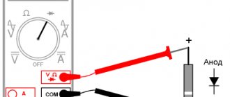
8) Diode continuity test and continuity test of conductors. Shows resistance if you measure the integrity of conductors. When checking diodes, it shows the voltage drop across the PN junction. The beauty of this function is that if a resistance of less than 100 Ohms is displayed (it is different for different models), a screaming signal is heard from the multimeter. A very convenient function for checking diodes, as well as the integrity of wires and fuses. If you buy a multimeter, be sure to buy one with a diode tester, otherwise such a multimeter will suddenly lose its functionality.
Briefly about the main thing
Any car enthusiast, radio enthusiast, or anyone who encounters electric current or the operation of household appliances should know how to use a multimeter correctly.
By following a few simple steps, you can find out the voltage, current, and resistance of an electrical circuit using any type of multimeter.
Car batteries, radio components and electrical devices can also be examined using a multimeter tester.
Ratings 0
How to check voltage with a multimeter
DC voltage measurement
As you know, there are two types of voltage: alternating and constant. Any multimeter has at its disposal the functions of measuring direct and alternating voltage. To measure the voltage, we must touch the leads of the power supply with the probes. As you can see, it is advisable to connect the minus of the power supply to the minus of the multimeter (COM-black probe), and the plus to the red probe of the multimeter.
measuring DC voltage using a multimeter
In order to measure DC voltage, we must set the switch to the “=V” icon or similar. Let's measure the voltage on the battery, since the battery produces a constant voltage.
To do this, set the switch on the multimeter to measure DC voltage. For a more accurate measurement, I set the range to 20 Volts. We touch the battery with the probes and look at the value on the display. 1.28 Volts, which is considered normal for a nickel-manganese battery.
In order to measure the voltage on any chemical current source, we simply set the range we need, then make sure that the probes are in their places (black on COM, red on V) and then touch the terminals of the battery, accumulator or any other current source.
Here, for example, I measure the voltage on a car battery.
You can also measure the voltage from a laboratory power supply that produces direct current. Let's demonstrate what it all looks like. I set the voltage on the power supply to 10 Volts and measure this voltage with a multimeter.
measuring DC voltage from the power supply
But what happens if we reverse the polarity? That is, we connect the red probe of the multimeter to the minus, and the black probe to the plus? The digital multimeter in this case will simply show a minus sign.
In modern multimeters, this icon is already combined with the AC icon and looks like this:
combined icon of direct and alternating voltage Here, using the function key, we ourselves choose what current we will measure: direct or alternating. Direct current is designated DC - direct current, which literally translated from English is “direct current”.
function switching key
In the example below, I measured the voltage on a lithium-ion battery.
AC voltage measurement
To check the alternating voltage, we must set the functionality selection switch to the “~V” icon. I think you are aware that the voltage in the outlets in your home is variable. Let's measure its value. As you can see, the multimeter showed 215 Volts, although it should be something around 220 Volts. This voltage is still within the operating range, so everything is fine.
For a multimeter with automatic range measurement, we need to select the AC icon on the display of your device using the FUNC key. AC - alternating current, which literally translated into English is alternating current.
This is how the voltage in an outlet is measured. 228 Volts, which is also quite normal.
Inserting probes into a socket
The probes must be connected to the appropriate connectors.
When installing the probes at the power point, it does not matter which one is inserted into which socket of the socket. The main thing is to strictly hold the wires by the insulation, and not by the exposed parts. It is important to ensure that the probes do not touch each other. Otherwise a short circuit will occur.
If the wires are connected correctly, the device display will reflect the current state of things. The digital voltage value will be displayed. It will never be equal to 220 V. An error of +/- 20 is considered normal. Therefore, if the screen displays 235-238 Volts, do not be alarmed. According to GOST, voltage deviations of 10% are permissible.
How to measure current with a multimeter
Measuring current in a DC circuit
In order to measure the current in a circuit, we must connect a multimeter to the open circuit.
On simple digital multimeters, you need to transfer the red probe to socket A or mA, which means Amperes. You haven't forgotten that current is measured in Amperes, right?
In order to measure the current in a DC circuit , we must set the switch to “=A”. So, in our case, we will supply voltage from the power supply to the computer fan.
We assemble this whole thing according to our scheme, but instead of an incandescent lamp we will have this fan.
Since my power supply already has a built-in ammeter, I can compare the readings on the multimeter and on the power supply. As you can see, they are completely identical. The current value in the circuit is 0.18 Amperes.
On a cooler multimeter we display one of these icons.
If you don’t know at all what approximate current strength should be in your circuit, then always set the switch to the highest range. In this case, at A. Let's check the current consumed by a 12-volt incandescent lamp. To do this, set the voltage on the power supply to 12 Volts and place a multimeter in the open circuit. That is, we do everything as it is according to this scheme.
As you can see, the current in the circuit is 0.707 Amperes. This means that an incandescent lamp at 12 Volts consumes a current of 0.707 Amps.
measuring DC current using a multimeter
Measuring current in an AC circuit
In order to measure the current in an AC circuit, we need to set the switch to the “~A” icon. In cool multimeters we put the function switch on one of these icons
and then we select using the “AC” function key, which indicates that we are going to measure the current in an alternating current circuit.
In order to demonstrate this, I will need a laboratory autotransformer (LATR).
laboratory autotransformer
This autotransformer allows you to obtain an alternating voltage of a lower value than in a 220 Volt home network. I set the voltage at the LATR output to 12 Volts. Don't forget that these 12 volts are alternating voltage. I connect the whole thing using the same scheme. By the way, the incandescent lamp here is more powerful, therefore, it will consume more current.
Why do you need to take measurements?
The electrical network is a dangerous and complex engineering system that requires operational skills and safety.
For a number of reasons, malfunctions and breakdowns may occur. To control and prevent them, it is necessary to carry out measurements. Also, breakdown or unstable operation of electrical appliances and equipment can be caused by a discrepancy between the mains voltage and the nominal voltage, and both excess and insufficient voltage can be dangerous.
What needs to be done to avoid overloading the electrical system - this can be achieved through the correct use of electrical equipment and measurements. Using a multimeter, you can determine the necessary parameters yourself, without involving qualified electrical laboratory specialists.
How to test a capacitor with a multimeter
In order to check the integrity of the capacitor with a multimeter, its capacitance must be 1 µF or higher. This trick only works with analog multimeters, as well as with digital range selecting multimeters, such as these.
As you know, capacitors are polar and non-polar. Read more here. Polar capacitors have a large capacity, so they are easier to check for functionality. How to do this? Let's take a look at the example below.
We have an electrolytic capacitor.
We set the multimeter to the continuity mode and touch the leads of the capacitor with the probes. We carefully watch the numbers on the scoreboard. They should increase as the capacitor charges.
As soon as I touched the leads, the multimeter immediately showed this value
in half a second
and then the value went out of range, and the multimeter showed one.
So what can we say? At the very initial moment of time, a completely discharged capacitor behaves like a conductor. As it is charged with current from the multimeter, its resistance increases until it becomes very high. Once the capacitor is charged, it means it is working. Everything is logical.
Capacitors of smaller capacity and non-polar capacitors can be tested using a tester only for a short circuit between its plates. Therefore, a different iron method is used here. Just measure the capacitance of the capacitor). Here I measured the capacitance of the capacitor, on which 47 uF was written. The multimeter showed 48 uF. Either the error of the capacitor or the multimeter. Since Mastech multimeters are considered to be quite good, we will attribute it to the capacitor error).
How to measure resistance with a multimeter
So, we have everyone's favorite digital multimeter
In order to measure resistance, we need to turn the function selection switch to “resistance measurement”. This is our entire top row in green with the letter Ω. The letter “K” tells us that we are going to measure kilo-ohms, and the letter “M” means that we are going to measure mega-ohms. The measurement limit is shown before the letter. If a 1 lights up on the multimeter display when measuring resistance, then we switch to a higher limit.
How to test a fixed resistor
So, we have this resistor.
We see the inscription “82R” on it. It means that its resistance should be 82 Ohms. You can read more about resistor markings in this article. To do this, apply one probe to one end of the resistor, and the other probe to the other end.
As you can see, the multimeter almost accurately showed the resistance value of this resistor.
How to test a variable resistor
Let's measure the resistance of the variable resistor. As you know, with a variable resistor we can change the resistance manually. The same applies to tuning resistors - this is one of the types of variable resistors.
This is his view from below. Here we see the inscription 47 KM. This means its resistance should be 47 KiloOhms between the two extreme contacts.
Using the handle, we can turn it clockwise or counterclockwise, thereby changing the resistance between the middle contact and the two outer contacts
Here is its schematic designation:
We place the probes at the extreme contacts. We measure the total resistance of the variable resistor.
Hmmm... A little different resistance. Our variable resistor is too old, which may be why its resistance does not match what is written on it. In order to check whether it is working, turn the variable resistor knob all the way counterclockwise and measure the resistance between the left and middle contacts. It should be close to zero.
Turn the handle clockwise, but not all the way. We measure the resistance between the middle and left contacts again.
We measure the resistance between the middle and right contacts.
The total should be the result of the resistance of the two extreme contacts. 12.2+27.6=39.8 Almost everything is correct. Therefore, our variable resistor is working properly.
Rules for measuring resistance
- Press the probes with some force onto the resistor terminals. In this way, you will eliminate the appearance of contact resistance, which, when pressed lightly, will add up to the measured resistance.
- Do not measure resistance under voltage! This could damage the multimeter or cause you an electric shock!
- When measuring the resistance of a resistor on a printed circuit board, double-check that the board is de-energized. Then unsolder one end of the resistor and then measure its resistance.
- Do not touch the resistor leads when measuring its resistance! The average human body has a resistance of about 1 KiloOhm and depends on many factors. Therefore, by touching the resistor terminals when measuring resistance, you introduce an error into the measurements.
- If you want to measure the resistor's resistance as accurately as possible, clean its terminals either with a knife or with the mildest sandpaper. In this case, you will remove the oxide layer, which in some cases introduces a noticeable error in the resistance measurement.
Types of device
A multimeter (multitester) is a device for measuring a variety of parameters of the electrical network, as well as other elements powered from it.
The device allows you to accurately determine network characteristics such as voltage, current, resistance and a number of other data. The multitester also makes it possible to test transistors, test cables and wires, test diodes, etc.
From the point of view of the design of the device itself, analogue and digital multimeters are distinguished. The devices differ in functional characteristics, accuracy of operation, workmanship, and configuration.
Analog testers are often called voltmeters or ammeters, since such devices are usually configured to perform 2-3 functions and nothing more. Analog devices show measurement results with a regular arrow on a scale. This technique is quite difficult to operate and requires some experience. A beginner will not immediately understand all the available scales in order to determine the final value of electrical data. In addition, analog equipment is not able to fix the arrow in position, which makes it difficult to work with.
The digital device displays measurement results in electronic form (on a liquid crystal monitor). The device is easy to operate and dramatically reduces the participation of the human factor, and therefore errors in measurements. The simplicity and accuracy of readings have made digital devices the most popular on the market.
How to make calls with a multimeter
All modern digital multimeters have a dialing function.
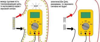
Continuity testing is the same “resistance measurement” function, but only in this case the multimeter makes a squeak if the resistance is less than 100 Ohms. Why is this function needed? In order to check the integrity of wires, fuses, incandescent lamps, printed conductors, and so on. A very convenient and indispensable function in any multimeter. Most often, the continuity icon is combined with a diode continuity indicator. It all looks something like this:
diode continuity
For example, I want to ring a light bulb and find out if it is intact? To do this, I put the switch on the corresponding icon and touch the lamp with the probes. The multimeter emits a heart-rending “piiiiip” sound, and the display of the multimeter shows the filament resistance reading. This means that the light bulb is alive, since the tungsten filament is not broken.
continuity test with a multimeter
Safety precautions
- You should definitely read the instructions for the device.
- Avoid touching parts with your fingers. The human body has its own resistance, which can affect the accuracy of the measurement.
- You need to wear non-conductive gloves when measuring. If there are none, dense rubberized models are suitable.
- If there is high humidity at the measurement site, it should not be carried out.
- When a measurement is being taken, modes cannot be switched.
- In case of mechanical damage or deformation of the braiding of wires and probes, the device cannot be used.
Multimeter, an affordable and simple device for home use. It allows you to accurately measure parameters. This contributes to safe and convenient work with the electrical network, and also ensures the serviceability of household appliances.
Proven Multimeters
With my many years of experience in the field of electronics, I have changed many multimeters. I would like to focus on two brands that made me very happy and still make me happy in my difficult task.
Multimeters DT9205
Large display, convenient functionality, automatic shutdown function, inexpensive cost. If you look through the pages of my website, you will see that I used exactly these models of multimeters in my practice. They are very comfortable and durable. Yes, they are large, but it's worth it. This multimeter fits very comfortably in your hand.
Here is the link to Aliexpress. Try to take exactly the same one as in the photo above. Its cost is in the range of 700-800 rubles.
