Measuring angles on the ground using a ruler.
If the ruler is held at a distance of 50 cm from the eyes, then a division of 1 mm will correspond to 0-02. When the ruler is 60 cm away from the eyes, 1 mm corresponds to 6 minutes, and 1 cm corresponds to 1 degree. To measure an angle in thousandths, hold a ruler in front of you at a distance of 50 cm from the eyes and count the number of millimeters between objects indicating the directions of the sides of the angle. The resulting number is multiplied by 0-02 and the angle is obtained in thousandths.
To measure an angle in degrees, the procedure is the same, only the ruler must be held at a distance of 60 cm from the eyes. The accuracy of measuring angles using a ruler depends on the ability to place the ruler exactly 50 or 60 cm from the eyes.
History of invention
The origins of this mathematical instrument go back to the priests in Egypt and Babylon, who established the measure of angles in degrees, minutes and seconds. However, trigonometry was not used in mathematics until the times of classical Greece.
In the second century BC, the astronomer Hipparchus of Nikia invented a trigonometric table for measuring triangles. Then Ptolemy included in his great astronomical book, Almagest, a table with angular increments from 0 to 180°, with an error of less than 1/3600 units. He also explained the method for constructing this table, and throughout the book he gave many examples of how to calculate unknown elements of figures using it.
Ptolemy was also the author of the so-called Menelaus theorem for solving spherical triangles, and for many centuries his trigonometry was the main tool for astronomers.
Perhaps at the same time, the scientists of India also developed a trigonometric system based on the sine function, which, unlike the sine currently used, was not a proportion, but the length of the side opposite the angle in the right triangle of that hypotenuse. Indian mathematicians used different meanings for this in their tables.
Thomas Blundeville spoke about a device specially created for drawing and measuring figures in his “A Brief Description of Universal Charts” of 1589. As the name suggests, he used it to edit navigational charts for use in high latitudes.
Other European mathematicians also described similar devices around the same time. Regardless of who first invented the instrument, by the early 17th century it had become standard practice for navigators and surveyors. By the 18th century, protractors began to appear in textbooks on surveying and geometry.
Protractors in the modern sense arose in the second half of the 18th century, when scientists such as Jesse Ramsden and Georg Friedrich Brander improved previously created devices.
At that time, the preferred materials for their manufacture were:
- tree;
- brass;
- silver;
- copper;
- Ivory.
In the first half of the 20th century, tin and celluloid began to be used.
The device began to be called a protractor (Russian) in 1610. The term comes from the medieval word protractor, meaning “to carry,” which in turn comes from the Latin word protrahere, “to pull forward.”
Visual determination of angles on the ground.
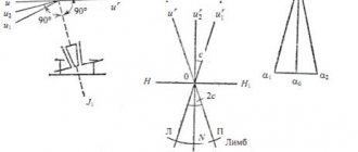
The visual determination of angles on the ground consists of comparing the measured angle with a known one. Angles of a certain size can be obtained in the following ways. A right angle is obtained between the direction of the arms, one of which is extended along the shoulders, and the other straight in front of you. From the angle formed in this way, you can set aside some part of it, keeping in mind that 1/2 part corresponds to the angle 7-50 (45 degrees), 1/3 to the angle 5-00 (30 degrees), etc.
The 2-50 (15 degrees) angle is obtained by sighting through the thumb and index fingers, placed at an angle of 90 degrees and 60 cm away from the eye, and the 1-00 (6 degrees) angle corresponds to the sighting angle of three closed fingers: index, middle and nameless.
Based on materials from the book Handbook of Military Topography. A. M. Govorukhin, A. M. Kuprin, A. N. Kovalenko, M. V. Gamezo.
Varieties and uses
A protractor is a simple goniometer for measuring or creating an angle. It looks like a round or semicircular disk with divisions. The disk can be made of plastic, durable paper, or sheet metal. Typical diameters are from 8 to 15 cm and divisions of 1° and 0.5°, also measuring 0.5 Gon (new degree). The accuracy ranges from 0.1 to 0.5° depending on the scale diameter. More precise instruments have a rotating rod with a scale (length up to a millimeter).
Partly because of their varied uses they are made in many shapes : the familiar semicircle, but also circles, rectangles, squares, or quarter circles (quadrants). They can also have different diameters. They are made from brass, steel, wood, ivory or plastic. The most common shape is a semicircle with a limiting scale of 180 degrees.
An Angle Protractor is a graduated round instrument with one rotating arm; used for measuring or marking. In construction, it is often necessary to measure an angle of 90 degrees. Sometimes a Vernier scale is included to give a more accurate reading. The instrument is widely used for producing architectural and mechanical drawings, although its use has declined with the advent of modern drawing software.
Universal bevel protractors are used by toolmakers; Since they make measurements through mechanical contact with an object, they are classified as mechanical protractors.
The angle protractor is used to measure and check angles with very tight tolerances. It reads up to 5 arcminutes (5 or 1/12°) and can measure from 0 to 360°.
Today, electronic devices are also used, which usually work with a rotary encoder. In addition, devices associated with the protractor are:
- theodolite;
- optical protractor in the construction industry and geodesy;
- inclinometer for determining slopes and indirect altimetry;
- sextant for navigation.
Instruments for measuring short distances
What tools are used to measure small distances, such as the diameter of wires, bolts, connecting parts, etc.? There is only one answer - highly accurate. These include calipers, bore gauges and micrometers. The desired object is placed between the bars or clamps of the measuring device, which correspond to the data on the scale. Built-in bayonets or rods are used to measure the depth of hollow objects. The accuracy of the readings is calculated to the tenth of a millimeter.
In what form can geodetic survey results be obtained?
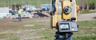
Upon completion of filming and camera work, a technical report is drawn up. It consists of statements of measurements and calculations, a catalog of coordinates, and a site plan. On the plan, symbols show in detail all the characteristics and features of the situation (relief, road conditions, positions of various objects, hard and soft points). The plan is created in graphic and electronic formats, taking into account the specified accuracy according to the customer’s technical specifications.
Additional documents are also attached to the report - outlines, field journals, binding diagrams, drawings. For individual projects, mandatory coordination of the received survey materials and plan with authorities, organizations for the operation of facilities or adjacent owners of land plots along their boundaries is required. In the future, the plan serves as the basis for any actions, for example, for:
- registration of a land plot with cadastral registration,
- construction or reconstruction of an object on the measured territory,
- carrying out work on the site for improvement and landscape design,
- developing recommendations for territory development or land reclamation projects.
Methods of marking work
Lateral leveling
It is used for moving out axes during detailed layout and when installing structures in the design position.
The intersection of the design point K with the structure is calculated as follows. Equal segments l are laid off from points A and B to obtain points A', B' and line A'B'. A theodolite is placed above point A' and pointed at point B'. A rail is applied to the horizontal structure and moved so that the reading along it is equal to l. The heel of the staff will give the position of point K. The position of point K' is also determined.
Polar coordinate method
It is used when laying out structures from points of theodolite and polygonometric traverses, if the distance between the initial and set-out points is small.
The position of point K on the ground is determined by plotting the angle β from the line AB and the horizontal line d along the line AK. Angle β = bA - bAK, where bA, bAK are the directional angles of the lines AB and AK, respectively.
The horizontal position d is determined by the formula
You can check the correct position of point K by plotting the angle β' from line BA and drawing line d'.
Straight corner serif
Here, the position K is determined by plotting the reference line AB and the angles β1 and β2, as in the drawing. The basis for b is the side of the alignment grid or its value. The design angles β1 and β2 are calculated by determining the difference between the directional angles.
Linear notching method
It is used to mark out the axes of building structures. Using a tape measure, d1 is plotted from point A, d2 is plotted from point B, the intersection of the lines is indicated by point K, which is the design point.
Crossing method
It is used to set out hard-to-reach points of the project if the use of other technologies is impossible. On the ground, alignments T1T'1 and T2T'2 are specified by the points of their intersection with the reference sides. The location of points T1 and T2 is determined by horizontal extensions of d1 and d2 from point B along the reference lines BA and BC, and points T'1 and T'2 - from point E along lines EF and ED.
Rectangular coordinate method
It is in demand if the geodetic basis is a construction grid, the vertices of which are fixed to the terrain. To carry out the design point K along line AD, a segment d1 is laid off, equal to UK - UA, and along the perpendicular to AD - segment d2, equal to Xk - XA. To construct segments and d2, the theodolite is placed above point A, by crossing the threads of the telescope, it is aimed at point D and from point A - in line AD, a horizontal extension of d1 is laid off to obtain point P. Next, the theodolite is installed above point P and the right angle APP is laid off '. In the direction PP' from point P, a horizontal line d2 is laid down with the point K positioned and secured.
Layout work is quite complex and it is better to order it from professionals.
offers a wide range of services in geology and geodesy. We work in Moscow and the Moscow region. The work is carried out at a high level of quality, in a short time and at competitive prices. Consultations are provided by telephone.


