Unfortunately, at present, not every person understands what is called simple, elementary things that almost every man should know. Personally, I began to notice that men had completely forgotten how to do things with their own hands. It often takes them quite a significant period of time to simply tighten a few screws, screw in a self-tapping screw, a bolt, and so on. It is for this reason that it is extremely important to do so in order to at least a little enlighten that person who literally does not understand what a thread is, what its pitch is, how it is all done, and so on.
At some point, I realized that I needed to write an article that would reveal this in more detail, so that every person could find the answer to the question posed.
Quite often, every person is faced with the problem of choosing a suitable fastener. With all this, there is a need for the correct choice of step. To begin with, we will figure out what a carving is and what nuance you need to pay attention to.
If we speak in simple and accessible language for every person, then a carving is just a surface where protrusions and depressions alternate. At the moment, several types of thread can be distinguished. However, the most popular is metric, although there are also imperial and so on.
The metric type of thread is currently the most common and in demand. Nominal diameter and pitch are the main features. The thread pitch is essentially the distance between two points that lie on a single plane. In even simpler terms, we can say that this is the distance between two protrusions on the surface.
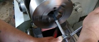
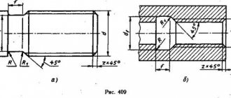
Measuring the internal diameter of a thread
The internal diameter of the cutting is controlled by a measuring device with pointed legs - calipers.
To organize computational work, you need to install the tool on a template part using a threaded gauge, and then make a comparison with the original internal diameter of the threaded connections. The caliper must be at an angle relative to the axis being measured. Also, measuring internal threads can be carried out with instruments for cylindrical threads. This is because the inside diameter has a smooth surface, which is ideal for the shape of the tips used in these instruments. Verification of the obtained measurements is done using plug gauges.
Measurement methods
There are quite a large number of different ways to determine the thread pitch. All of them are characterized by their own specific features that need to be taken into account. Common methods include:
- Using a regular ruler.
- The use of a special tool that can be used to determine the value in question. A thread pitch meter can be purchased at a specialty store.
- A caliper is a precision instrument. It is used quite often due to its high accuracy and versatility in use.
All of the above methods allow you to obtain fairly accurate data. The easiest way to take measurements is to use a thread-finding tool, but you can get by with a regular caliper.
Concept of thread pitch
Threads are used to connect a wide variety of products. To determine the bolt thread, you need to consider the distance between the same sides of the profile. The features of this concept include the following points:
- To determine the main parameters, a measurement is required.
- An inaccurate result can be determined by using a ruler.
- To increase the accuracy of measurements, you need to analyze several threads. That is why, depending on the length of the threaded surface, an analysis of 10 to 20 turns is carried out.
- It is recommended to take measurements in millimeters. In some cases the number is converted to inches.
The distance between the depressions can be measured using a special tool. The thread gauge is represented by a combination of special steel plates that have special cutouts. Various values are applied to the surface.
How to measure a nut
Most nuts have metric threads. Measuring the thread diameter will require a little more steps than in other cases. If possible, it is recommended to check the size of the bolt or screw used for it rather than the nut itself. This way you can achieve a more accurate result.
The value obtained after measuring the internal thread is an indicator of the internal diameter din.
In order to accurately determine the diameter of the metric thread of the hardware, you will need to find out the correspondence between din and the outer diameter of the bolt used. This is done using a special table.
Accuracy is controlled through the use of certain pass-fail gauges. One part should connect well with the nut, the second part, on the contrary, should not.
The nuts differ in appearance, and it is easy to determine upon detailed inspection. To find out the standard of the fastener, you may need to measure the height of the hardware, since there are high, low, extra high and other options.
Turnkey dimensions are also used to classify hex nuts. This is explained by the fact that hardware also differs in its types.
To accurately measure the thread pitch, it is possible to use the method considered in the case of a bolt. You will need a thread gauge or you will have to count the number of turns at the required interval.
Determining the dimensions of inch nuts
To check the thread dimensions of an inch nut, you need to examine the threads of the bolt or other hardware used with it. If you don’t have a suitable one at hand, but have information about the presence of an inch thread, then use the appropriate thread gauge. Do not forget to divide the resulting value by 25.4 mm.
Determining washer dimensions
For washers, a short designation in the form D is used, which stands for the diameter of the metric thread of the hardware used for the fastener.
To accurately measure indicators, a ruler or caliper is suitable. The result is a value that is slightly higher than the figure in the notation. This is explained by the fact that free movement is required during installation, which requires a small gap.
So, you have a bolt or nut with unknown thread parameters, and there is no measuring tool at hand other than a ruler. Let us immediately warn you that using a ruler can only get a rough result, so if you are going to regularly take such measurements, it is better to purchase a thread gauge or caliper.
How are bolts marked correctly?
The first number shows how much load the connection can withstand. The second is the ratio, multiplied by 10, of the two limits - fluidity and strength. So, if you see the marking on the bolts - “8.8”, this means that with a load of more than 8 tons per square centimeter they will break.
Interesting materials:
What is hosting and domain in simple words? What are channel keywords? What is a continuum in simple words? What is KPI in simple words? What is speech culture in simple words? What is a quantile in simple words? What is the lexical meaning of the word 5th grade? What is the lexical meaning of the word rule? What is Bitcoin mining in simple words? What is marketing definition in your own words?
Measuring thread pitch without a thread gauge
Parts with external thread
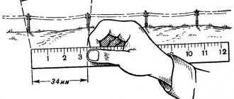
Often the need to determine the thread pitch arises sporadically, at one time. And, of course, in such a situation there is no thread gauge at hand, and it makes no sense to buy one for one-time measurements. It will be useful to learn how to measure the thread pitch with a ruler or caliper. These measuring tools make it quite easy to determine the desired parameter.
The easiest way is to measure the threads of a bolt or other externally threaded part. When measuring a metric thread, it is recommended that you first attach the ruler to the threaded part and try to align the millimeter divisions of its scale with the tops of the ridges of the threaded profile. If they coincide, then the step is 1 mm. Otherwise, you will have to carry out slightly more complex measurements.
To determine the thread pitch, you need to count the number of turns on a section of a rod of a certain length, for example, 10 mm or 20 mm. To obtain a more accurate result, it is recommended to take measurements on a 20 mm area. The required length is measured by applying a ruler to the bolt shaft, or using a caliper. It would be more accurate to measure the bolt thread pitch with a caliper. In the measured area, count the number of turns. After this, the length of the section must be divided by the resulting number of turns minus one turn. As a result, we obtain the value of the thread pitch.
When determining the pitch of an inch cutting, it is necessary to measure the length of the rod equal to one inch (25.4 mm). For accurate measurements, it is better to use a ruler or caliper with an inch scale. The number of turns in this area will be the thread pitch. If the length of the threaded section is less than one inch, then you need to determine the number of turns in a section of half an inch (12.7 mm), and then multiply the result by 2.
Internally threaded parts
There are two ways to measure the thread of a nut or other internally threaded part without a thread gauge. The first method involves selecting an exactly suitable counter bolt and then measuring its thread pitch. If you can’t find the counter bolt, then you need to use a strip of paper (this is method No. 2).
It should be pressed against the thread so that an imprint of the profile remains on the paper. You can improve the visibility of marks by tracing the edges with a marker. After this, on paper you need to mark the distance between the extreme marks with a ruler and count the number of turns. Then the resulting distance is divided by the number of turns minus one turn. Instead of measuring paper using this method, you can use a pencil, match or other soft wood product of a suitable size, which is pressed against the thread.
Types and parameters of threaded connections
A threaded connection is the main method of joining two structural elements together. In plumbing and construction practice, threaded connections are used when installing pipelines, shut-off and control valves and connecting consuming equipment to utility systems.
Threaded connection
This article presents threaded connections. We will look at their varieties, the components of the fastener, and methods for determining the size and configuration of the thread.
Purpose and scope of application
A thread, according to the provisions of GOST No. 2.331-68, is defined as a surface formed by a set of alternating depressions and protrusions of a certain profile, located on the internal or external walls of a body of rotation.
The functional purpose of the thread is:
- keeping parts at the required distance in relation to each other;
- fixing parts and limiting the possibility of their displacement;
- ensuring the tightness of the connection of abutting structures.
The basis of any thread is a helical line, depending on the configuration of which the following types of thread are distinguished:
- cylindrical - thread formed on a cylindrical surface;
- conical - on a conical-shaped surface;
- right - thread, the helix of which is directed clockwise;
- left - with a helical line counterclockwise.
Threaded connection is a joining of two parts by means of a thread, ensuring their immobility or a given spatial movement relative to each other. Such compounds are classified into two main categories:
- connections made using special connecting elements - screws, studs, nuts and washers (this includes all types of flange mounting);
- connections formed by screwing together two abutting structures without third-party fasteners (in plumbing - a coupling connection of pipes).
Pipe coupling diagram
Current GOSTs define the following basic thread parameters:
- d - nominal outer diameter of the screw or bolt, indicated in millimeters;
- d1 is the internal diameter of the nuts, the size of which must coincide with the value d of the mating fastener;
- p is the thread pitch, indicating the distance between two adjacent helix ridges;
- a - profile angle, indicates the angle between adjacent protrusions of the helix in the axial plane.
The thread pitch determines which class it belongs to - main or small. In practice, the differences between them are that small threaded connections (all fasteners with a diameter of 20 mm or more are made in this configuration), due to the minimum distance between the ridges of the helical line, are more resistant to self-unscrewing.
Advantages and disadvantages
The wide distribution of threaded connections is due to the presence of many operational advantages in this fastening method, which include:
- reliability and durability;
- the ability to control the compression force;
- fixation in a given position due to the self-braking effect;
- the ability to assemble and dismantle using widely used tools;
- comparative simplicity of design;
- a wide range and standard sizes of fasteners, their low cost;
- minimum dimensions of fasteners in comparison with the dimensions of the parts to be connected.
The disadvantages of these connections include uneven distribution of load along the helical thread line (about 50% of the pressure falls on the first turn ), accelerated wear and weakening of the joint during frequent disassembly of the fastener, and its tendency to self-unscrew under the influence of vibration loads.
Types of threaded connections
Depending on the type of profile, threads are classified into the following types:
- metric;
- inch;
- cylindrical pipe;
- trapezoidal;
- persistent;
- round.
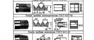
Types of thread profiles
The most common is metric thread (GOST No. 9150-81). Its profile is made in the form of an equilateral triangle at an angle of 600 with a pitch of turns from 0.25 to 6 mm. Fastening elements are available in diameters of 1-600 mm.
There is also a metric conical thread that uses a 1:16 taper. This configuration provides a sealed joint and locks fasteners without the need for lock nuts. The table below indicates the main parameters of the metric profile.
Metric Thread Size Chart
Inch threads do not have regulatory standards in domestic construction documentation. The inch profile is made in a triangular shape with an angle of 550. The pitch of the profile is determined by the number of turns in a section 1″ long. The design is standardized for fasteners with an outer diameter from 3/16″ to 4″ and a number of turns per 1″ from 3 to 28.
The tapered inch thread has a profile angle of 600 and a taper of 1:16. This profile ensures high tightness of the connection without additional sealing materials. This is the main type of thread in small diameter hydraulic and pressure pipes.
Inch thread sizes
Cylindrical pipe threads (GOST No. 6357-81) are used as fastening and sealing threads. Its profile has the shape of an isosceles triangle with an angle of 550. In order to obtain increased tightness, the profile is made with rounded upper edges without additional gaps in the places of depressions and protrusions. This type of thread is standardized for diameters 1/16″-6″, the pitch varies between 11-28 turns per 1″.
Pipe threads are always made in a small configuration (with a reduced pitch), which is necessary to maintain the wall thickness of the structures being connected. This type of profile is widely used for connecting steel pipelines of heating and water supply systems and other cylindrical parts.
Pipe thread sizes
Accuracy classes and marking rules
A thread belonging to the inch type, as indicated by GOST, can correspond to one of three accuracy classes - 1, 2 and 3. Next to the number indicating the accuracy class, put the letters “A” (external) or “B” (internal). The full designations of thread accuracy classes, depending on its type, look like 1A, 2A and 3A (for external) and 1B, 2B and 3B (for internal). It should be borne in mind that class 1 corresponds to the coarsest threads, and class 3 corresponds to the most precise threads, the dimensions of which are subject to very stringent requirements.
Maximum size deviations according to GOST
To understand what parameters a specific threaded element corresponds to, it is enough to understand the designation of the thread that is applied to it. The designation in question is used by many foreign manufacturers who work according to American standards relating to elements of threaded connections.
An example of a symbol for an inch thread
This marking contains the following information about the thread:
- nominal size (outer diameter) – first digits;
- number of turns per inch of length;
- group;
- accuracy class.
How many mm are 3 4 inches?
Inch pipe 3/4 inch: Pipe diameter 3/4 inch (nominal diameter): 20 (mm); 3/4 inch pipe dimensions (outer diameter): 26.8 (mm);
Interesting materials:
How many shares are traded on the MICEX? How many algorithms does the Rubik's cube have? How much alcohol can you bring into Zanzibar? How many ampelous petunias should I plant in a pot? How many amperes of direct current are dangerous to humans? How many amps does the fast charger have? How many Armenians live in California? How many Armenians live in Israel? How many atheists are there in Russia? How many cars are there in Russia 2022?
Accuracy classes and marking rules
A thread belonging to the inch type, as indicated by GOST, can correspond to one of three accuracy classes - 1, 2 and 3. Next to the number indicating the accuracy class, put the letters “A” (external) or “B” (internal). The full designations of thread accuracy classes, depending on its type, look like 1A, 2A and 3A (for external) and 1B, 2B and 3B (for internal). It should be borne in mind that class 1 corresponds to the coarsest threads, and class 3 corresponds to the most precise threads, the dimensions of which are subject to very stringent requirements.
Maximum size deviations according to GOST
To understand what parameters a specific threaded element corresponds to, it is enough to understand the designation of the thread that is applied to it. The designation in question is used by many foreign manufacturers who work according to American standards relating to elements of threaded connections.
An example of a symbol for an inch thread
This marking contains the following information about the thread:
- nominal size (outer diameter) – first digits;
- number of turns per inch of length;
- group;
- accuracy class.
If you have a question, how to determine the type and size of thread Connecting fittings for pipes and hoses
connections use the table below.
Please note the following:
- connections with inch threads are highlighted in color
- next to the inch step size in tpi the step size in mm is indicated
- connections with external tapered threads usually do not have a threaded groove
- BSPT and NPT conical fittings are very similar, but BSPT has a mark on the hexagon
An important note - situations are quite possible when the inch and metric pitches are very close in size (this is possible on JIC connections).
Read also: Scraper conveyor operating principle
In this case, it is possible to confuse the inch thread. American cylindrical inch thread UNF (Unified Thread Standard)
UNC UNF and metric threads.
Threaded fasteners are one of the most popular for attaching parts, assembling products, equipment, and structures. There is no industry where it is not used. There are many thread characteristics: pitch, tolerance range, number of starts, nominal diameter, profile type and others. One of these is units of measurement, inches or millimeters.
There is often a situation when it is necessary to replace a bolt, pin or screw, but the fastener purchased for maximum similarity “by eye” is not screwed into the mounting hole. One of the reasons is an attempt to screw a fastener with an external inch thread into a hole with a metric thread. Or vice versa. This situation often arises when replacing fasteners on products or equipment manufactured in the UK, USA, Japan, or Australia. There, inch threads have priority.
How to distinguish an inch thread from a metric thread? There are two main ways - by measuring the pitch and diameter or using a special tool.
Measurement
Fastener thread markings are done differently in metric and inch systems. In metric, this is an indication of the thread pitch (the distance between adjacent threads) in millimeters, while in inch it is the number of threads per inch.
Determining the type and size of fastener thread comes down to the following operations. Use a caliper to measure the diameter. Then, using an inch ruler or caliper, measure the number of threads in one inch and the thread pitch. You can also use a regular ruler with measured 2.54 mm (1 inch = 2.54 mm). The metric thread pitch on small fasteners can be found by measuring the distance between 10 turns and dividing the resulting value by 10. The resulting values should be compared with the table below. The maximum match in diameter, number of turns, pitch indicates the size and type of thread. It should be noted that there are many different types of inch threads. The table shows the most common ones in the diameter range from 8 mm to 64 mm.
You can also use a thread gauge to measure threads. This is its direct purpose. A thread gauge is a set of plates with protruding teeth for a specific thread, united on a single axis. The thread size is engraved or permanently inked on the plate itself. Checking the thread is done by applying plates that are closest in size to the thread. If there is a complete match, without gaps, the thread can be considered defined, and its size can be viewed on the thread gauge plate. Thread gauges are produced separately for metric, inch threads or both types.
Screen thread gauge for Android
Even an ordinary smartphone can replace a thread gauge in everyday life. To do this, you need to download the Android application “Thread pitch meter. Thread gauge" from the developers of the Smart Tools toolkit. Simply apply a screw to the screen, look for the exact match of the turns and find out the pitch. Various types of threads are available in the mobile application: metric, inch and pipe standards.
Screen thread gauge for Android
As for inch and metric threads, there are approximate matches. But it’s hard to imagine how you would try to screw a 1/2″-20 UNF bolt into an M12x1.25 hole. As for the M14x1.25 thread, yes, everything is correct.
Evgeniy Guryevich, 1) On threading tools, as well as in reference tables, it is indeed customary not to use the “X” sign. But not in the designation of LARGE, but MAIN THREADS. In practice, many foreign manufacturers still provide full markings of the thread size, for example 12x1.75, both on the tool and on the packaging with fasteners. Soviet and Russian companies producing cutting tools also often “sin” with this. You don’t have to look far for examples - this is the former Sestroretsk tool plant, the German company Reyher. This is done mainly so that the user does not have doubts about the correct choice of the product. It's no secret that most salespeople in stores, mechanics in factories, and sometimes even designers don't know (don't remember) the pitch table for not only small threads, but also major threads. In these cases, detailed size markings help.
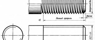
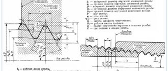
Metric thread. Profile.
Metric thread profile according to GOST 9150 (ST SEV 180)
The nominal thread profile and the dimensions of its elements must correspond to those indicated in the figure and table.
d is the outer diameter of the external thread (bolt); D—outer diameter of the internal thread (nut); d2 is the average diameter of the bolt; D2 - average diameter of the nut; d1 - internal diameter of the bolt; D1 - internal diameter of the nut; P - thread pitch; H is the height of the original triangle; R is the nominal radius of curvature of the bolt root; H1 - working height of the profile.
Notes:
- The shape of the bolt thread root is not regulated and can be either rounded or flat-cut. A rounded cavity shape is preferred.
- The shape of the nut thread root is not regulated.
The table shows the dimensions of the thread profile elements. The shape of the screw thread cavities is not regulated by the standard; rounding of the depressions (with radius R) reduces stress concentration and increases the strength of the screw under cyclic loading.
According to GOST 24705 (ST SEV 182), the thread is metric, the main values of thread diameters are determined by the formulas:
where d3 is the internal diameter of the bolt.
GOST and the need for unification
For a long time, manufacturers performed theoretical calculations of thread pitch using their own methods and manufactured fasteners using their own technologies. With this approach, connectors from different brands often turned out to be incompatible or did not provide suitable joint quality, which often caused problems for users.
Particular difficulties arose during the assembly of machines, apparatus and other component equipment. Literally each element had to be marked separately so that later it could be placed correctly. Banal preventive cleaning of tools or machines, parts of which were supplied by two or more factories, turned into real torture.
Therefore, from the beginning of the 20th century, the issue of standardization became seriously concerned. The matter was approached with the utmost seriousness, taking into account even the experience of the 12th century, or rather the practice-tested formula stating that the distance between adjacent turns should be equal to 20% of the diameter of the rod. Naturally, they took into account that in those distant times the fasteners were made of wood, and only 20 years later they began to tighten the most loaded points with studs and protect them with nuts machined from a single piece of especially strong rock. Today, completely different materials are relevant, which have completely different requirements.
Food for thought
The first path to standardization began to be paved precisely in Russia: at the Tula plant they began to work according to Nikita Demidov’s drawings, and check the results using the calibers he proposed. This made it possible to control the accuracy of casting and execution of individual parts.
Yes, the famous industrialist did not think specifically about the thread pitch (how to measure it or find the optimal one), but sought to unify production as a whole. And he achieved his goal: in 1787, a commission under the tsarist army purchased 500 domestic guns and the same number of English ones. The inspectors disassembled each of them, arranged the elements according to their functional purpose and thoroughly mixed each group, after which they tried to assemble it. In the case of the Russian models, this was possible - even though they required grinding in, they eventually passed the zeroing - but the pride of the British craftsmen remained a pile of useless iron.
This was the impetus for the following events:
Each regiment created a platoon responsible for servicing weapons, and it regularly received consumables marked with notches to replace small items that had failed.
In France, in 1790, they approved the first pan-European basic system of measures, adopting m and its “derivatives” – cm and mm – as a unit of length, which is still used today; England, by the way, remained with its inches and feet.
Connecting thin-walled parts
If it is necessary to connect thin-walled parts, then it will not be possible to directly use a threaded connection: the number of turns may be too small to reliably hold the fastener within the thickness of the part. In such cases, a flange connection is used. In this case, the edge of the part adjacent to the joint is strengthened by special stamping or welding of a flange - a thickening in which holes are made and threads are cut. If the configuration of the product allows, then sometimes instead of a full flange, only nuts are welded at the fastening points.
Flange connection
If the parts to be connected are cylinders of the same diameter and thickness, there is another method: an internal thread is cut on one cylindrical surface, and an external thread of the same nominal diameter is cut on the other. Next, the parts are screwed onto each other. This connection method does not require the application of large forces to the fastening point and is used for lightly loaded structures, such as, for example, cylindrical instrument casings.
Rectangular thread
Table 3 presents data on rectangular threads.
Rectangular threads are most often made with a square tooth profile. But some manufacturers use rectangular profiles with an extended flange of the horizontal part for reinforcement
Table 3: Thread dimensions and helix pitch
| Nominal thread diameter d, mm | Step P | |||||
| 1 row (preferred) | Row 2 (permissible) | large | small 1 | small 2 | small 3 | small 4 |
| 8 | 2,00 | 1,50 | 1,25 | |||
| 9 | 2,00 | 1,50 | ||||
| 10 | 2,00 | 1,50 | 1,25 | |||
| 11 | 3,00 | 2,00 | 1,25 | 1,00 | ||
| 12 | 3,00 | 2,00 | 1,50 | |||
| 14 | 3,00 | 2,00 | ||||
| 16 | 4,00 | 2,00 | 1,50 | 1,00 | 0,75 | |
| 18 | 4,00 | 2,00 | ||||
| 20 | 4,00 | 3,00 | 2,00 | |||
| 22 | 8,00 | 5,00 | 4,00 | 3,00 | 2,00 | |
| 24 | 8,00 | 5,00 | 4,00 | 3,00 | 2,00 | |
| 26 | 8,00 | 5,00 | 4,00 | 3,00 | 2,00 | |
| 28 | 8,00 | 5,00 | 4,00 | 3,00 | 2,00 | |
| 30 | 10,00 | 6,00 | 3,00 | |||
| 32 | 10,00 | 6,00 | 3,00 | 2,00 | ||
| 34 | 10,00 | 6,00 | 3,00 | |||
| 36 | 10,00 | 6,00 | 3,00 | 2,00 | 1,50 | |
| 38 | 10 | 7 | 6,00 | 5,00 | 3,00 | |
| 40 | 10 | 7 | 6,00 | 5,00 | 3,00 | |
| 42 | 10 | 7 | 6,00 | 5,00 |
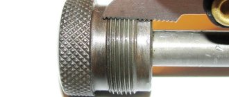
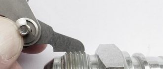
How to determine threads with a caliper or ruler
To determine the type of thread on the fitting, a caliper is needed.
How to correctly take measurements using a caliper is shown in the figure below.
Measurements must be made accurate to tenths of a millimeter.
| Outer diameter, mm | Inner diameter, mm | Thread pitch, threads per inch | Thread pitch | BSP | Metrics | Inch UNF | Inch NPT |
| 9,3-9,7 | 8,5-8,9 | 28 | 1/8″ | ||||
| 9,3-9,7 | 8,5-8,9 | 27 | 1/8″ | ||||
| 9,7-9,9 | 8,2-8,6 | 1,5 | M10x1.5 | ||||
| 10,9-11,1 | 9,7-10,0 | 20 | 7/16″-20 | ||||
| 11,6-11,9 | 10,2-10,6 | 1,5 | M12x1.5 | ||||
| 12,4-12,7 | 11,3-11,6 | 1/2″-20 | |||||
| 12,9-13,1 | 11,4-11,9 | 19 | 1/4″ | ||||
| 12,9-13,1 | 11,4-11,9 | 18 | 1/4″ | ||||
| 13,6-13,9 | 12,2-12,6 | 1,5 | M14x1.5 | ||||
| 14,0-14,3 | 12,7-13,0 | 18 | 9/16″-18 | ||||
| 15,6-15,9 | 14,2-14,6 | 1,5 | M16x1.5 | ||||
| 16,3-16,6 | 14,9-15,4 | 19 | 3/8″ | ||||
| 16,3-16,6 | 14,9-15,4 | 18 | 3/8″ | ||||
| 17,6-17,9 | 16,2-16,6 | 1,5 | M18x1.5 | ||||
| 18,7-19,0 | 17,3-17,6 | 16 | 3/4″-16 | ||||
| 19,6-19,9 | 18,2-18,6 | 1,5 | M20x1.5 | ||||
| 20,5-20,9 | 18,6-19,0 | 14 | 1/2″ | ||||
| 20,7-21,1 | 18,3-18,7 | 14 | 1/2″ | ||||
| 21,6-21,9 | 20,2-20,6 | 1,5 | M22x1.5 | ||||
| 22,0-22,2 | 20,2-20,5 | 14 | 7/8″-14 | ||||
| 22,6-22,9 | 20,6-21,0 | 14 | 5/8″ | ||||
| 23,6-23,9 | 22,2-22,6 | 1,5 | M24x1.5 | ||||
| 25,6-25,9 | 24,2-24,6 | 1,5 | M26x1.5 | ||||
| 26,1-26,4 | 24,1-24,5 | 14 | 3/4″ | ||||
| 26,3-26,7 | 23,7-24,1 | 14 | 3/4″ | ||||
| 26;6-26,9 | 24,3-24,7 | 12 | 1,1/16″-12 | ||||
| 29,6-29,9 | 27,4-27,8 | 2 | M30x2 | ||||
| 29,8-30,1 | 27,6-27,9 | 12 | 1,3/16″-12 | ||||
| 29,6-29,9 | 28,2-28,6 | 1,5 | M30x1.5 | ||||
| 32,6-32,9 | 30,5-30,9 | 2 | M33x2 | ||||
| 33,0-33,2 | 30,3-30,8 | 11 | 1″ | ||||
| 33,0-33,3 | 30,8-31,2 | 12 | 1,5/16″-12 | ||||
| 32,9-33,4 | 30,3-30,8 | 11,5 | 1″ | ||||
| 35,6-35,9 | 33,4-33,8 | 2 | M36x2 | ||||
| 37,6-37,9 | 36,2-36,6 | 1,5 | M38x1.5 | ||||
| 40,9-41,2 | 38,7-39,1 | 12 | 1,5/8″-12 | ||||
| 41,6-41,9 | 39,4-39,8 | 2 | M42x2 | ||||
| 41,5-41,9 | 39,0-39,5 | 11 | 1,1/4″ | ||||
| 41,4-42,0 | 39,2-39,6 | 11,5 | 1,1/4″ | ||||
| 44,6-44,9 | 42,4-42,8 | 2 | M45x2 | ||||
| 44,6-44,9 | 43,2-43,6 | 1,5 | M45x1.5 | ||||
| 47,3-47,6 | 45,1-45,5 | 12 | 1,7/8″-12 | ||||
| 47,4-47,8 | 44,8-45,3 | 11 | 1,1/2″ | ||||
| 47,3-47,9 | 45,1-45,5 | 11,5 | 1,1/2″ | ||||
| 51,6-51,9 | 49,4-49,6 | 2 | M52x2 | ||||
| 51,6-51,9 | 50,2-50,6 | 1,5 | M52x1.5 | ||||
| 59,4-59,8 | 56,5-56,8 | 11 | 2″ | ||||
| 59,9-60,2 | 56,4-56,7 | 11,5 | 2″ | ||||
| 63,3-63,6 | 61,3-61,8 | 12 | 2,1/2″-12 |
CONTACTS
st. B. Okruzhnaya 4-b, s. Petropavlovskaya Borshchagovka, Kiev-Svyatoshinsky district, Kiev region, 08130, Ukraine
Postal address: PO Box 70, Kyiv-162, 03162
information:
+38
branches
- Kyiv
- Sumy
- Krivoy Rog
- Kyiv
- Gorishni Plavni
- Vinnitsa
- Berdichev
- Kherson
- Khmelnitsky
- Pervomaisk
- Kyiv
- Lviv
SUPPLIERS
Manufacturers of components, materials and units
- Oleodinamica Marchesini
- Manuli Hydraulics
- B&C
- OMT
- Meiller
see everyone