4.3 Marking
4.3.1 Springs are marked on tags by stamping, engraving or waterproof paint. The tag is attached to the spring or packaging area. For springs made of wire with a diameter of more than 5 mm, it is allowed to apply electrographic markings on one of the support turns.
4.3.2 Marking includes the following information:
— trademark of the manufacturer;
— month and year of issue;
— spring (batch) number;
— drawing number or symbol of the spring;
— by agreement between the customer and the manufacturer, other necessary information can be included in the marking.
Calculation of compression and extension springs
FORMULAS AND METHODS FOR CALCULATING SPRINGS MADE OF ROUND STEEL (according to GOST 13765-86) METHOD
FOR DETERMINING SPRING SIZES ACCORDING TO GOST 13765-86 1. The initial values for determining the size of springs are forces F1 and F2, working stroke h, the highest speed of movement of the movable end of the spring at loading or unloading vmax, endurance Np and outer diameter of the spring D1 (preliminary). If only one force F2 is specified, then instead of the working stroke h, the value of the working deformation S 2 corresponding to the given force is taken for calculation.
2. Based on the value of the specified endurance Np, the spring’s belonging to the corresponding class is preliminarily determined according to the table. 1.
3. Based on the given force F2 and the extreme values of the inertial gap δ, the value of the force F3 is calculated using formula (2).
4. According to the value of F3, using the table. 2, the spring discharge is preliminarily determined.
5. According to table. 11-17 find the line in which the outer diameter of the spring coil is closest to the preset value D1. In the same line, find the corresponding values of force F3 and wire diameter d.
6. For springs made of hardenable steel grades, the maximum shear stress τ3 is found from table. 2, for cold-drawn and heat-treated springs τ3 is calculated taking into account the values of tensile resistance Rm. For cold-drawn wire, Rm is determined from GOST 9389-75, for heat-treated wire - from GOST 1071-81.
7. From the obtained values of F3 and τ3, as well as from the given value of F2, using formulas (5) and (5a), the critical speed vk and the ratio vmax / vk are calculated, confirming or denying that the spring belongs to a predetermined class. If the conditions vmax / vk < 1 are not met, springs of classes I and II are assigned to the next class or the calculations are repeated, changing the initial conditions. If it is impossible to change the initial conditions, performance is ensured by a set of spare springs.
8. Based on the finally established class and category in the corresponding table for the parameters of the coils of the springs, in addition to the previously found values F3, D1 and d, the values c1 and s3 are found, after which the remaining dimensions of the spring and the dimensions of the assembly are calculated using formulas (6)-(25) .
CLASSES AND CLASSES OF SPRINGS
Below we consider helical cylindrical compression and tension springs made of round steel with indexes i = d/D from 4 to 12.
The given data applies to springs for operation at temperatures from -60 to +120°C in non-aggressive environments. Springs are divided into classes, types and categories (see below).
The class of springs characterizes the loading and endurance conditions, and also determines the basic requirements for materials and manufacturing technology.
Spring discharges reflect information about force ranges, grades of spring steels used, as well as standards for permissible stresses.
The absence of collision of coils in compression springs is determined by the condition vmax / vk < 1, where vmax is the highest speed of movement of the moving end of the spring during loading or unloading, m/s;
vk is the critical speed of compression springs, m/s (corresponds to the occurrence of collision of the coils of the spring due to inertial forces). ENDURANCE AND DURABILITY OF SPRINGS
When determining the size of springs, it is necessary to take into account that at vmax> vk, in addition to tangential torsional stresses, contact stresses arise from the collision of coils moving by inertia after the parts mating with the springs have slowed down and stopped. If there is no collision of coils, then springs with low stresses τ3 have the best endurance, i.e. class I springs according to table. 1, intermediate - cyclic springs of class II and worst - springs of class III.
In the presence of intense collision of turns, endurance is in the reverse order, i.e.
increases not with a decrease, but with an increase in τ3. Resilience is in the same order, i.e. reduction of residual deformations or settling of springs during operation. 1. CLASSES OF SPRINGS according to GOST 13765-86
| Spring class | Type of springs | Loading | Endurance NF (established no-failure operating time), cycles, not less | Inertial collision of turns |
| I | Compression and stretching | Cyclic | 1×10⁷ | Absent |
| II | Cyclic and static | 1×10⁵ | ||
| III | Compression | Cyclic | 2×10³ | Allowed |
Note
.
The specified endurance does not apply to extension spring hooks. 2. SPRING DISCHARGES according to GOST 13765-86
| Spring force at max. deformations F3, H | Diameter of wire (rod) d, mm | Material | Hardness after heat treatment HRC | Maximum shear stress during torsion τ3, MPa | ||||||
| steel grade | Workpiece standard | |||||||||
| I | 1 | 1 — 850 | 0,2 — 5,0 | according to GOST 1050 and GOST 1435 | Wire class I according to GOST 9389 | — | 0.3Rm | GOST 13766 | ||
| 2 | 1 — 800 | Wire of classes II and IIA according to GOST 9389 | GOST 13767 | |||||||
| 22,4 — 800 | 1,2 — 5,0 | 51ХFA-Ш according to GOST 14959 | Wire according to GOST 1071 | 0.32Rm | ||||||
| 3 | 140 — 60000 | 3,0 — 12,0 | 60S2A, 65S2VA, 70CA3 according to GOST 14959 | Wire according to GOST 14963 | 47,5…53,5 | 560 | GOST 13768 | |||
| 51HFA according to GOST 14959 | Wire according to GOST 14963 | 45,5…51,5 | ||||||||
| 4 | 2800 — 180000 | 14 — 70 | 60S2A, 65S2VA, 70S3A, 60S2, 60S2ХА, 60S2HFA, 51HFA according to GOST 14959 | Hot rolled steel. round according to GOST 2590 | 44,0…51,5 | 480 | GOST 13769 | |||
| II | 1 | 1,5 — 1400 | 0,2 — 5,0 | according to GOST 1050 and GOST 1435 | Wire class I according to GOST 9389 | — | 0.5Rm | GOST 13770 | ||
| 2 | 1,25 — 1250 | Wire class II and IIA according to GOST 9389 | GOST 13771 | |||||||
| 37,5 — 1250 | 1,2 — 5,0 | 51ХFA-Ш according to GOST 14959 | Wire according to GOST 1071 | 0.52Rm | ||||||
| 3 | 236 — 10000 | 3,0 — 12,0 | 60S2A, 65S2VA according to GOST 14959 | Wire according to GOST 14963 | 47,5…53,5 | 960 | GOST 13772 | |||
| 65G according to GOST 14959 | Wire according to GOST 2771 | |||||||||
| 51HFA according to GOST 14959 | Wire according to GOST 14963 | 45,5…51,5 | ||||||||
| 4 | 4500 — 280000 | 14 — 70 | 60S2A, 60S2, 65S2VA, 70S3A, 51HFA, 65G, 60S2HFA, 60S2XA according to GST 14959 | Hot rolled steel. round according to GOST 2590 | 44,0…51,5 | 800 | GOST 13773 | |||
| III | 1 | 12,5 — 1000 | 0,3 — 2,8 | according to GOST 1050 and GOST 1435 | Wire class I according to GOST 9389 | — | 0.6Rm | — | GOST 13774 | |
| 2 | 315 — 14000 | 3,0 — 12,0 | 60S2A, 65S2VA, 70S3A according to GOST 14959 | Wire according to GOST 14963 | 54,5…58,0 | 13509 | GOST 13775 | |||
| 3 | 6000 — 20000 | 14 — 25 | 60S2A, 65S2VA, 70S3A according to GOST 14959 | Hot rolled steel. round according to GOST 2590 | 51,5…56,0 | 1050 | GOST 13776 | |||
Notes:
1. The maximum shear stress during torsion is given taking into account the curvature of the turns. 2. Rm - tensile strength of spring materials
The means of regulating the endurance and durability of cyclic springs within each class at constant specified values of the working stroke are changes in the difference between the maximum shear stress during torsion τ3 and the shear stress during working deformation τ2.
Increases in the difference τ3 - τ2 cause an increase in the endurance and durability of cyclic springs of all classes while simultaneously increasing the size of the units. A decrease in the differences τ3 - τ2 is accompanied by reverse changes in the service qualities and sizes of spaces in the mechanisms for placing springs. For class I springs, the design stresses and properties of the metal are regulated so that, with νmax/ νk ≤ 1, the specified endurance of the springs under the action of force F1 (spring force during preliminary deformation) of at least 0.2F3 (spring force at maximum deformation) is ensured for all feasible locations and the values of the working sections on the force diagrams of the stress difference τ3 - τ2, and τ2 - τ1, (tangential stress during preliminary deformation). Class II cyclic springs with νmax/ νk ≤ 1, depending on the location and size of the working areas, can be subjected to conditions of both unlimited and limited endurance. Cyclic springs of class III, for all ratios νmax/νk and a relative inertial gap of springs δ of no more than 0.4, are characterized by limited endurance, since they are designed for extremely high tangential torsional stresses, to which, at νmax/νk > 1, contact stresses from the collision of coils are added. All static springs that remain in a deformed state for a long time and are periodically loaded at a speed of νmax/νk belong to class II. The introduced restrictions on design stresses and wire properties (see table above) ensure unlimited resistance of static springs with residual deformations of no more than 15% of the maximum deformation s3. The permissible residual deformations of static springs are regulated by the coordination of the spring forces at the working deformation s3 on the force diagrams, and an increase in the difference F3 - F2 helps to reduce the residual deformations. Technological means of regulating the endurance and resistance of springs are determined by the technical requirements documentation. EXECUTION OF WORKING DRAWINGS OF COMPRESSION AND EXTENSION SPRINGS
1. Compression spring made of round wire with unpressed and unpolished outer turns.
2. Compression spring with 3/4 turns pressed at each end and supporting surfaces ground 3/4 of the circle.
3. Tension springs made of round wire with hooks open on one side and located in the same plane.
SUPPORT COIL OF COMPRESSION SPRINGS LENGTH OF COMPRESSION SPRINGS
It is recommended to take the length of compression springs as Lo <= (D1 - d).
You can take Lo up to 5 x (D - d), but then the springs must work on the guide rod or in the guide sleeve.
In this case, a gap z is maintained between the spring and the mating part depending on the value of the average diameter D of the spring. Gap value z, mm
Related documents:
compression springs; paraboloid springs; calculation of a bending leaf spring; calculation of torsion springs from round wire; GOST 13764-86 » Cylindrical screw springs for compression and tension made of round steel. Classification"; GOST 13766-86 “Cylindrical compression and tension springs, class 1, category 1, made of round steel. Basic parameters of turns"; GOST 13767-86 “Cylindrical compression and tension springs, class 1, category 2, made of round steel. Basic parameters of turns"; GOST 13768-86 “Cylindrical screw springs for compression and tension, class 1, category 3, made of round steel. Basic parameters of turns"; GOST 13769-86 “Cylindrical compression springs, class 1, category 4, made of round steel. Basic parameters of turns"; GOST 13770-86 “Cylindrical compression and tension springs of class II, category 1, made of round steel. Basic parameters of turns"; GOST 13771-86 “Cylindrical compression and tension springs of class II, category 2, made of round steel. Basic parameters of turns"; GOST 13772-86 “Cylindrical compression and tension springs of class II, category 3, made of round steel. Basic parameters of turns"; GOST 13773-86 “Cylindrical compression screw springs of class II, category 4, made of round steel. Basic parameters of turns"; GOST 13774-86 “Cylindrical compression screw springs of class III, category 1, made of round steel. Basic parameters of turns"; GOST 13775-86 “Cylindrical compression springs of class III, category 2, made of round steel. Basic parameters of turns"; GOST 13776-86 “Cylindrical compression screw springs of class III, category 3, made of round steel. Basic parameters of turns."
Classification
Depending on the nature of the load acting on them, springs are of the following types:
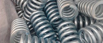
Depending on the design, the springs can be twisted conical - these are used as shock absorbers, and twisted cylindrical - screw, for example in staplers or hole punches. Lamellar ones are used as springs, and spiral ones are used in mechanical watches. Belleville springs are used when significant force is applied but little deformation is applied, for example in cranes. In addition, there are flat and torsion bar varieties of these products.
