What is AVR
This is a block consisting of several nodes, which automatically switches the load between the main and backup current sources. Some single-phase and three-phase models of gasoline and diesel generators are equipped initially. To switch the load, you only need to install a special switch after the electric meter. The position of the power contacts is controlled by the main power source.
Read also: How to make a hazel grouse decoy
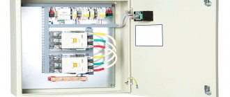
Almost all models with a battery-powered power plant can be equipped with autonomous ATS systems. In this case, ATS cabinets are used to install backup input units. In this case, ATS panels (Figure 1) can be placed directly next to gas generators or the units can be installed in a common electrical panel.
Figure 1. Example of an ATS electrical panel
Is it possible to connect welding when ABP is running?
You can connect welding to a generator when there is enough power. Source burforum.ru
You probably understand that autostarting a gas generator is good, but the carburetor unit cannot handle all the powerful equipment. As an example, we will consider the choice of a device that will be sufficient for electric welding, as one of the most powerful energy consumers possible in domestic conditions. At the same time, we will consider compromise solutions when the main device is not only a welding machine, but also a generator with a diesel, gas or carburetor. By the way, no less power will be required for a carpentry workshop if it is equipped with professional equipment.
So, if your autostart system for a gasoline generator is equipped with an inverter and the output power of the unit indicated in the documents or on the case coincides with the welding power consumption, that’s not all. There are not only basic, but also additional quantities that affect voltage:
- power consumption of the welding machine;
- voltage range;
- maximum inverter for welding current;
- arc voltage parameters;
- expected duration of the work process;
- Efficiency
Note: it is also important to consider the condition of the electrical wiring in the building and the welding modes provided for the time when the generator will automatically start in the event of a power outage.
It is very important to take into account the factor of false information, that is, not very powerful inverters connected to the ABP circuit are not always capable of delivering 220 V. But in such cases, we turn to the technical parameters of the welding machine and, if the unit is capable of operating at a voltage of 150-200 V, it means everything is fine and you won't have any problems.
Technical parameters Source asutpp.ru
When it is known in advance that when the main power source is turned off, a reserve will be automatically introduced, and welding work will be carried out, it will not be amiss to study the table given above. This way you can choose the optimal ratio for a generator with ABP and an electric welding machine.
Advice: when choosing the ratio of the power of the generator and the welding machine, it is best if there is a reserve at the output, that is, when you enter a reserve, you will get more than what is needed for the operation of the equipment.
About contactors
Thus, the use of conventional relays is out of the question for us; only specialized contactors are suitable. For higher powers there is also an option with motorized drives, but this is expensive and redundant for typical home use.
To make a mechanical interlock, you need to select contactors that can work in pairs. Typically, mutual interlocking is achieved by installing identical contactors next to each other and installing an additional option - a mechanical interlock. It is sold separately from contactors and costs pennies.
Read also: Why broilers sit on their legs
Mutual electrical interlocking is possible if the contactor has additional signal contacts that operate to open. Sometimes they are immediately built into the contactor, sometimes they can be purchased and installed as an option.
Leading contactor manufacturers have such equipment in their lines. So finding and buying a kit is not difficult. True, prices for branded contactors are an order of magnitude higher than ours/Chinese ones. Since the number of switching cycles is not expected to be large, the choice of Chinese contactors is quite justified. The only disadvantage is that the contactor coils hum quite loudly during operation.
More about the switching power. The contactor contacts must be able to handle the maximum amount of power you are allowed to draw in your home. For me it is 10 kW, so I chose contactors for a permissible current through one contact of approximately 50 amperes. It is worth noting that for some reason the switched power for a typical three-phase contactor is indicated in the passport as the total for all three phases, so you need to carefully look at what the permissible current is through exactly one contact.
Model range and prices.
Expert - the main line of RUENERGY, includes 3 models. Supplied in a plastic case with protection against dust and precipitation IP65. Designed for both outdoor and indoor installation. Schneider Electric components. The control element is replaceable 105/207/200. Without changing the equipment, change the functionality!
| Expert | 4-pole | Built-in | Professional |
| E105-38/3-P Schn | E207-63/3-P ABB (4) | 105-63/3 ABB | E200-63/3-M (4) ABB GSM |
| E105-65/3-P Schn | E207-45/3-P Schn (4) | 105-38/3 Schn | E200-45/3-M (4) Schn GSM |
| E105-95/3-M Schn | 105-65/3 Schn |
How to assemble an AVR with your own hands
If you are familiar with the basics of electrical engineering, you can try to make an ATS yourself, based on the diagram. But it is better, of course, to entrust this to a specialist with experience in assembling electrical panels.
To assemble the AVR unit with our own hands, we will need:
- Three-pole starters with blocks of additional contacts (1NO and 1NC) – 2 pcs. The power is selected based on the input circuit breaker installed in your panel.
- Automatic switches: Three-pole, current corresponding to contactors - 2 pcs (QF1, QF2) and 1 pc. to protect the voltage control relay - 3p S6A (QF3). Single-pole – B6A – 1 piece (QF4).
- Voltage monitoring relay CM-PVE or equivalent (KV).
- Modular contactor with 220V coil and three contacts (2NO and 1NC) (KL1). How to assemble an AVR with your own hands.
- Signal lamps for 220V, one red and one green (HL1, HL2).
- A metal cabinet with a mounting plate and dimensions corresponding to the equipment being installed (everything should not be end-to-end, and there should not be too much free space).
- DIN rail – approximately 0.5 m.
- DIN rail terminals - if desired, you can do without them by connecting cables directly to breakers and contactors.
Below is an approximate location of the equipment in the shield. Then everything is simple, first we wire the power lines using the mounting wire PV3 or PuGV (the cross-section is not lower than the cable coming from the network), and then the control circuits with the same wire are only 1mm2. PuGV and PV3 are necessarily pressed into NShVI tips.
Approximate location of the equipment in the panel.
Reserve input circuit with zero break
Without a break, it can be used if you have two independent power lines or cable inputs, from which you actually connect the entire house. But when the backup line is some kind of autonomous energy source - a UPS or a generator, then you will have to break both the phase and the neutral.
Since the main network in 90% of cases is made with a solidly grounded neutral, and from a generator or UPS it comes with an isolated one. Here it is impossible to combine the zero working conductor from the network with the zero from the generator.
Naturally, all contactors are connected after the kWh meter. QF are modular circuit breakers in a home panel.
If you have a second power source that does not supply voltage automatically, for example, a gasoline generator without starting equipment. Which must first be manually started, warmed up and only then switched, then the circuit can be slightly changed by adding one single button.
Due to this, automatic switching will not occur. You choose the right moment for this by pressing it when needed. This button SB1 is mounted parallel to the contactor coil.
When the voltage at the main input does not disappear for a long time, but periodically disappears and appears (the reasons may be different), in this case it is not advisable to constantly switch the contactors back and forth. Here it is advisable to use a special attachment to a PVI-12 type contactor with a time delay.
Video description
Generator with autostart for home and garden. Autonomous and practical solution.
Types of ABP
All automatic reserve input blocks can be classified according to the following criteria:
- voltage;
- reserve input sections (quantity);
- type of network (single- and two-phase);
- power.
The connection diagram for automatic generator start can be configured so that not all wiring fed by the main source is started, but only those units where shutdown may be critical. For example, in a hospital this is how an intensive care unit and operating room are connected, and in the private sector a workshop and/or sawmill. This is not difficult to do: when installing the wiring, vital or technically critical blocks are output separately from all the others, so the ABP is inserted directly into this circuit.
ABP device
The simplest ATS circuit for a three-phase network Source piter220.ru
All automatic generator start systems consist of three main blocks.
- Contactors or terminals for switching input and load circuits;
- Logical and indicating devices.
- Relay blocks responsible for controlling (start/stop) the generator.
ABP can become a lifesaver not only when the main power line is disconnected, but also during voltage dips, which can sometimes occur in suburban areas due to weak transformer substations. That is, the inclusion of a start function in the circuit when the voltage drops to 90% (instead of 220 V - 200 V) of demand. This will allow the electric motors to operate without interruptions and unnecessary load. With this option, generator autostart systems allow you to save on repairs and the purchase of new equipment. The contact group is responsible for starting the reserve circuit, and the input voltage is monitored by the RKF or phase control relay.
The simplest ATS circuit for a single-phase network Source asutpp.ru
Now, using the diagram above, let’s take a closer look at how a diesel or gas generator with automatic start allows you to eliminate dips (complete shutdown or drop) in the voltage from the main power source. Here, too, everything is very simple: when ≈220 V is supplied stably, the phase control relay keeps the terminals in the normal closed state. If there is any breakdown on the power line side, the saturation of the RKF solenoid becomes weak and cannot hold these terminals, hence they open. In those situations where an inverter is present, as indicated in the above diagram, it will begin to generate ≈220 V, which is necessary for the consumer. If the main power cannot be restored within the time set depending on the power of the batteries, then the controller sends an autostart command to the generator.
As soon as the contactor block receives voltage from the main transformer substation, the automatic generator start system operates in the reverse order - the terminals are switched and the entire circuit is powered according to the intended design. To put it simply, the signal when restoring the transformer from the power line gives a command to shut off the fuel hose, be it gasoline, diesel fuel or gas. The valve blocks the fuel supply and the engine stops.
ATS on two contactors or magnetic starters
Using two contactors, you can implement a very simple and understandable scheme for automatic power backup:
The circuit is very simple, designed for single-phase circuits. There are a minimum of details, but the circuit is nevertheless ready for practical use. Operating procedure: turn on SA1 and SA2 alternately. If the voltage was at input 1, then it will power the load, input 2 will be backup. In this scheme there are no explicit main and backup inputs. If the voltage disappears at one of the inputs, the power will switch to the other. If voltage reappears at the disconnected input, nothing will happen until the voltage at the switched-on input disappears.
The circuit is quite reliable even without mechanical interlocking of the starters, which, however, will also not be superfluous. To switch the power to another input, it is enough to briefly turn off the power to the input using the SA1 or SA2 circuit breaker. The logic of the circuit is simple, so there is nothing special to describe. The closing contacts of the contactors must be designed for the full load current; for the breaking contacts this does not matter (block contacts can be used).
Currently, the industry produces a wide range of ready-made AVR units. Basically, this is a programmable controller in a block with output relays. The most popular and cheap devices are usually made for mounting on a DIN rail, approximately 15 wide standard single-pole circuit breakers. Let's consider one of them, relatively simple.
Self-production of AVR
If you purchased a generator with an electric starter, you can automate the process of introducing the reserve yourself. To do this, you need to choose a scheme that meets the characteristics of your home network. After that, buy all the necessary parts, taking into account the power of consumers.
You will need:
- Universal controller.
- Contactors (for the simplest circuit - at least 2).
- Electrical cabinet.
- Three-level operating mode switch.
- Power supply for 1 - 3 Amps.
- Automation for starting/stopping the generator engine (if it is not equipped with one).
- Connecting cables, working tools.
Stages of work:
- Cabinet installation. Select a suitable location for the electrical panel (preferably closer to the main input).
- Installation of parts. Place all components so that all contactors and terminals are accessible.
- Connecting lines. Strictly follow the diagrams and observe the terminal assignments. Use the markings on the covers and housings of the devices. Make sure that the wires do not cross. Lastly, connect the input wires, of course, with the input circuit breaker turned off.
- After installation, be sure to test the operation of the ATS unit.
Description of possible ABP connection methods
Relationship between contacts KM1 and KM2 Source asutpp.ru
When connecting a generator with auto-start, the most important thing in this process is to take care to exclude the slightest possibility of counter currents entering the circuit. This can happen if the contactors operate incorrectly, that is, power will come from two sources. At the top there is a simple diagram with terminals K1 and K2, which should always be in different positions. When one turns on, the other necessarily opens and vice versa. At the moment, you can find more than one diagram on the Internet indicating how autostart occurs for a gas generator, but the general principle, taking into account the position of K1 and K2, will never change.
The principle of connecting the reserve input never changes Source asutpp.ru
Also, the location of the ABP on the diagram never changes, although physically it can be hung anywhere - even on the ceiling. The essence of the insert is that the machine will always be between the electricity meter and the substation, and no one will install it after the meter, so that you do not have to pay for the electricity that you yourself produce.
Schematic diagram for a private house Source asutpp.ru
When it comes to a private home, an autostart for a generator can be assembled according to the diagram above. Yes, you see exactly the fundamental warrant for the ABP installation, but in order to draw up a specific installation diagram, you need to know exactly the location, type and power of the equipment that should be started from the reserve. So, if you show a little ingenuity, you can tailor this scheme to the needs of your building and the electrical appliances located in it.
Detailed connection diagram for ATS Source asutpp.ru
Selecting ATS
The table below will help you decide on the type of ATS.
| ATS type | Device Features | Action |
| Single acting | Two sections. One working and one backup | Connects a backup line in case of power failure on the main one |
| Double acting | Sections are equivalent | You can connect any line, regardless of voltage availability |
| With restoration | Monitors the presence of voltage at the main input after switching to backup power | When voltage appears on the main line, it transfers the circuit (with a slight delay) to its original state |
| No recovery | Switches sections after voltage loss at the main input | Operator intervention is required to switch to main mode |