What to do if there is no light in the house? A current generator can help solve the problem. But if this equipment also fails, checking the generator with a multimeter will help determine the malfunction. Regardless of the type and brand, with the help of this device, once you find out the cause of the malfunction, you can carry out simple repairs yourself.
There are many types of generators, from large and powerful industrial devices to small automotive devices. But the testing algorithm using the tester is the same for any generator.
What components and parts are checked using a multimeter?
This operation involves diagnosing the electrical part, and checking the following parts:
Voltage measurements are taken at the generator output;- the rotor excitation winding is checked for open circuit or short circuit to the housing;
- checking the stator windings for breakdown and open circuit;
- carry out fault detection of the diode bridge, capacitor;
- faults in the voltage regulator and brushes are detected;
Performing each of the listed operations requires special knowledge and skill to carry out measurements, so each test should be considered in more detail.
General recommendations for repair and operation
p, blockquote 45,0,0,0,0 —>
At the slightest suspicion of a malfunction of the battery charging system (change in the brightness of the lamps, blinking of the indicator lamp, difficulty starting the engine, overheating of the device, etc.), you should immediately check the functionality of the generator, especially in the cold season.
p, blockquote 46,0,0,0,0 —>
To ensure that the generator lasts longer, follow these simple rules:
p, blockquote 47,0,0,0,0 —>
- do not allow the generator to become excessively dirty (it has technological openings for ventilation, dirt can get there), clean its surface;
- periodically check the belt tension;
- monitor the condition of the stator windings, this can be done through the technological holes, they should not be darkened;
- poor contact of the control wire can lead to failure of the relay regulator;
- To prevent overcharging of the battery and failure of the vehicle's electronic systems, periodically check the voltage on the battery with the engine running (charge voltage).
And may your generator last longer!
p, blockquote 48,0,0,0,0 —>
You should know what the resistance of the high-voltage ignition wires should be when replacing them.
Not everyone knows what is needed to independently diagnose a car.
Video - how to check the voltage regulator of the VALEO generator in Renault cars:
p, blockquote 50,0,0,0,0 —> p, blockquote 51,0,0,0,1 —>
May be of interest:
Very often these regulators are assembled with a brush assembly, at least on half of all modern generators that are brought to me for repair just like that. And they change when the brushes wear out, so no one will check or even repair it now. And generator brushes can easily last for ten years. Earlier, back when everyone drove Zhiguli, Moskvich and Volga cars, there were relay, and later transistor relay regulators, they were soldered and repaired quite successfully. And now even the car itself, if something happens, will indicate a malfunction with a check engine light, all that remains is to consider the error and change it.
Output voltage level measurement
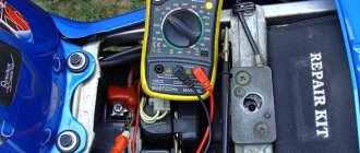
For each individual unit this value will be different. Let's take a closer look at checking a car generator. Set the voltage measurement mode on the multimeter scale. First you need to check the voltage with the engine turned off. To do this, measure the voltage value at the battery terminals.
We connect the red probe to the positive terminal, and attach the black one to the minus terminal. A charged, serviceable battery will produce a value of up to 12.8 V. We start the engine. Then we take a measurement.
Now this value should be no more than 14.8 V, but no less than 13.5 V. If the voltage level is higher or lower, the generator is faulty.
Checking the generator on the car
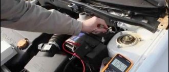
First of all, you need to see if the alternator belt is intact. If it is not torn, then the belt tension is checked. Then it's time for the battery. Using a tester (multimeter), we measure the voltage at the terminals. It should be around 12−12.7 volts. If everything is fine, start the engine. If the battery is discharged, charge it and start the engine again.
We measure the voltage at the battery terminals. It should be within specified limits, usually from 13.2 to 14.5 volts. But on modern cars these limits may differ. If you have an instruction manual, you can read it. Deviation from the specified values in any direction is a malfunction. These deviations can be of three types:
- Lack of charging current - the generator does not work.
- There is a charging current, but below the minimum value -
- Voltage above the maximum value means the battery is overcharged.
All three cases indicate an existing malfunction in the vehicle's electrical supply system. it is necessary to carry out a comprehensive check of the generator.
But before that, conduct a visual inspection of all the wires and cables that go from the generator to the battery. There should be no visible damage, breaks or oxidation of the electrical wiring. Be sure to check the terminals on the battery, starter and alternator. They must be clean and dry. Any oxidation, rust or dirt must be cleaned off. Often this helps restore lost contact and the car begins to work as expected. If this does not help, we proceed to a detailed check.
Using a Multimeter
For further inspection, it is better to remove the generator from the car. First of all, remove the relay regulator from the generator and check it. To check the voltage stabilizer, you will need a multimeter and a charger with regulated voltage. It would be better to use a power supply instead of a charger. Voltage adjustment from 0 to 16 volts will be sufficient.
Connect the plus of the power supply to the regulator - usually this is a male plug connection. Hook the minus to the minus, it is usually output to the ear of the relay mount. Connect the red wire of the tester to the positive wire of the power supply, the black wire to the negative wire. Connect two stripped wires to the brushes, one for each. A light bulb is connected to the other pre-stripped ends (it can be removed from the rear lights of the car during testing). The test bench is ready.
Continuity of the relay regulator
Connect the power supply to the network, carefully use the regulator knob to begin raising the voltage. At the same time, monitor the multimeter readings. The light bulb should not light up at the very beginning, but as the voltage rises it should light up, first at half-incandescence and as the voltage increases, the brightness should increase.
When the 14.5 volt mark is reached, the regulator should operate, cutting off the voltage. The light should then go out. It is generally accepted that the stabilizer is working if it cuts off the current at values from 14.2 to 14.8 volts. If this happens at lower or higher values, then the voltage regulator is faulty. The relay is also faulty if there is no current cutoff at all.
If the relay malfunctions, replace it with a new one. If it is working properly, we continue checking.
Checking the rotor winding
To perform this operation, it is necessary to dismantle and disassemble the unit. When performing a self-test, do not forget to set the device to the circuit resistance measurement mode.
Additionally, a value of no higher than 200 Ohm is set. These routine maintenance works are carried out in 2 stages:
- Measuring the resistance value of the rotor windings. To do this, we attach the probes to the rings of the moving part of the engine and determine the value. This will make it possible to determine the probability of a winding circuit break at a value above 5 ohms. If the device shows less than 1.9 ohms, a turn short circuit has occurred. Most often, the chain breaks at the junction of the rotor winding lead to the ring. You can determine the defect by moving the wire with a probe at the soldering points, as well as by detecting darkened and crumbling wire insulation. In the event of a break or short circuit (short circuit), the wires become very hot, so the breakdown can be detected by visual inspection.
- A circuit test is performed to detect a short circuit to the frame. We position the generator rotor conveniently for operation. Then we bring one probe to the rotor shaft, and attach the second to any ring. If the winding is working properly, the resistance reading will go off scale. If it shows low resistance, this part should be sent for rewinding. When rewinding the rotor, it is important to maintain perfect balancing.
What elements does the stator of a synchronous generator consist of and the principle of operation?
Stator elements:
- Package of stator windings;
- Stator core or package;
- Wires for connection output.
The stator itself is made of three windings, three different current values are formed in them, this circuit is a three-phase output. The ends of each winding extend from the generator body (they are connected to it), the second end is connected to the rectifier. To concentrate and enhance the magnetic field in the generator, a core made of metal plates is used.
The stator winding of a synchronous generator is located in special slots, usually there are 36 such slots. In each slot, the winding is held by a wedge. This wedge is made of insulating materials.
Checking the stator windings
Checking the stator begins with a visual inspection. We pay attention to external damage to the housing and insulation, and places where wires are burned during a short circuit.
The faulty unit should be rewound or replaced. If the external integrity of the wires is established, we begin to investigate using a tester.
Before starting work, you should make sure that the unit is disconnected from the network and that there is no contact between the leads of the stator windings.
When performing work to check the normal state of the node, we make sure:
- The integrity of the winding circuit. To do this, set the device to resistance measurement mode. We attach the probes to the first pair of terminals, then check the 1st winding and the 3rd, 3rd and 2nd terminals. If, during a break, the pointer of an analog device goes off the scale, the windings should be rewinded.
- In the absence of an interturn short circuit and to the housing. To do this, connect one of the tips to the terminal, the second to the body. If the windings are short-circuited, the scale will have a lower resistance value than those in good condition.
How to test a generator with a multimeter
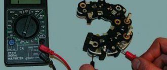
The diode bridge of the generator can be checked with a multimeter, but you can also use the stand that was used to check the regulator.
But before that, first of all, without removing the rectifier bridge from the generator, connect the red wire of the tester to terminal 30 of the generator, and the black wire to the housing. Set the tester operating mode to dial (diode icon). If it is not there, then set it to 1-2 kOhm. The multimeter should show infinity. If the readings are different, the diode bridge is faulty.
Then check the current rectifiers for breakdown. Leave the positive (red) probe on terminal 30, touch the negative one to the bridge mounting bolts one by one. The multimeter display should show infinity in all cases; any others mean a breakdown.
Next, connect the positive probe to the axle mounting bolts, and the negative probe to the generator housing. In this case, the tester should also output infinity.
But in practice, such verification is most often not enough. In most cases, it is necessary to ring the generator in more detail.
Careful testing
To do this, unscrew the fastening bolts of the rectifier unit, disconnect the copper wires of the stator winding and remove the diode bridge from the generator. Now you can test each semiconductor individually. Before checking, it is advisable to rinse the stabilizer with running water using a medium-hard brush, and then dry thoroughly. For quick drying, a hair dryer is quite suitable.
Attach one of the tester probes to the diode plate, connect the second to the central terminal of each diode fixed to this plate. Then swap the probes. In one case, the multimeter should show infinity, in the other - a nominal resistance of approximately 570-590 Ohms. Rectifiers are considered faulty if:
- In the first and second measurements (when the polarity was changed), the multimeter readings are the same;
- Diode resistance is greater or less than nominal values.
Perform the same actions with the second plate of the diode bridge. If a fault is detected in one or more diodes, it will be easier to replace the entire rectifier unit. True, there are craftsmen who replace failed diodes individually, but such work requires a certain skill and dexterity.
Checking the armature and stator windings
Further inspection requires completely disassembling the generator. First of all, visually check the anchor. Brush rings should not show any blackening, chipping or wear on the treadmills. Blackening and slight wear can be smoothed out with zero-grade emery cloth. Rings with deep grooves must be replaced or, if the thickness of the rings allows, turned on a lathe.
The armature winding should not clearly smell like burning . The color of the winding must be uniform and free of damage and breaks. To check the armature winding for a break, you will need a multimeter. Set the operating mode to continuity testing or resistance measurement and connect the probes to the brush rings. The winding resistance should be within 3-5 Ohms. Then leave one probe on the ring, connect the other to the body. The multimeter display should show infinity.
The generator stator is diagnosed after removal from the housing. First of all, carry out a visual inspection. There should be no visible damage to the wire or its insulation. Then connect the tester wire to the stator housing. With the second wire, touch the terminals one by one. There are only three of them. The tester must be in dialing mode. If the display shows infinity, this indicates that the stator is working properly.
Further testing consists of diagnosing the windings. The resistance of all three windings must be the same.
Before assembling the generator, you need to check and, if necessary, replace the bearings. When turning, they should not jam or make a creaking sound. This means that they are very worn out and will soon fail. Therefore, it is better to replace them immediately .
Voltage Regulator Troubleshooting
Remove and disconnect the wires from the part. We inspect the condition of the brushes. They should not have significant defects or chips. In the guide channels of the brush holder, the generator brushes must move freely. If they protrude beyond the edge by less than 5 mm, the generator regulator should be changed.
The test is carried out using batteries and a 12-volt light bulb. The voltage of the second power source must be at least 15 V, so we connect the batteries in series to the car battery and adjust the value to the desired value. We attach the plus from the 1st power source to the output contact, and the minus to ground.
The light bulb is installed between the brushes. When connecting a 16 V source, it should not light up. With a weaker battery, it lights up. If proper combustion is not observed, the regulator should be replaced.
Signs of generator failure
Signs of abnormal operation of a car generator may include:
- no “battery” indication on the dashboard when the ignition is turned on;
- the “battery” light glows after starting the engine;
- periodic blinking of the “battery” signal indicator while driving;
- the smell of burnt electrical wiring in the generator area;
- failure to start the engine after parking.
Lack of battery charge with a faulty generator leads to problems with starting the engine. More dangerous is a malfunction associated with exceeding the current and voltage of the car battery charge. Many car enthusiasts use a donor battery to start the engine, after which they disconnect the battery terminals to switch to charging their own battery. At this moment, the vehicle's electrical equipment is powered by a generator.
If the generator is faulty, the voltage in the on-board network may be more than 17 volts, which leads to breakdown of the protective zener diodes in the engine control unit. In this case, expensive repairs to the engine control unit are required.
What is it, where is it located, how does it work
This part of the car is responsible for maintaining the voltage of the on-board network within certain limits. The regulator controls the ambient temperature, rotor speed, electrical load level and other parameters. It also protects the sensitive elements of the generator from overloads and is responsible for activating the field winding and other systems.
The product is located directly in the generator. Regardless of the machine model, the principle of operation of the regulator is the same - when the voltage increases or decreases, the component reduces or increases the excitation current to return the indicators to the desired level.
This is what the voltage regulator looks like
The most common causes of breakdown
- Short circuit of the diode bridge or generator brushes. The result is a shutdown of the generator or a transition to uncontrolled voltage.
- Stabilization voltage shift. In this case, the stability of the voltage is maintained, but it is constantly either low or high.
- Oxidation or burnt contacts.
- Changing the size of the gap between the contacts.
- Relaxation of spring tension.
- Problems with the windings - breaks or short circuits.
Breakdowns can be identified at an early stage - to do this, pay attention to the ratio of fuel consumption to the efficiency of the car. If the car consumes much more fuel than necessary, but performs worse, most likely the problem is in the regulator. A sure sign is the strength of the headlights at night. If, when driving at night, you notice that the intensity of the side lights and instruments has decreased significantly, it’s time to check the regulator.