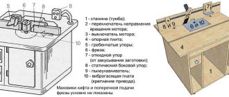
Milling is a type of mechanical processing of materials using a special cutting tool - a milling cutter. The method allows you to obtain a high level of accuracy and the degree of roughness of the processed surface. In addition, it is distinguished by significant productivity.
Surface processing is carried out by the method of up milling, when the rotation of the cutting tool is opposite to the direction of feed, and by down milling - a method in which the direction of rotation of the cutter and feed are identical. By using cutters with cutting edges made from modern super-hard materials, the grinding operation can be replaced.
Milling equipment is divided into universal and specialized. In the first case, these are general-purpose machines for performing longitudinal and continuous milling, with or without tools mounted on a console. The second contains a mechanism for cutting threads, splines, making gears and keyways, and pattern milling.
In production, there is often a need to produce several pieces, a batch, or even a series of identical parts. For this purpose, milling equipment equipped with a pantograph is used.
In the household, the functions of a milling machine are usually performed by a manual milling machine. To perform the maximum range of work, the milling cutter is equipped with a whole set of accessories. The main equipment is supplied with the equipment, additional equipment can be purchased or manufactured independently. These are a variety of stops, clamps, templates. But you can go even further and make a copier for milling volumetric parts.
Milling and copying equipment: operating principle
The operating principle of such a device is to clearly transmit the movements of the copy head through the holder profile to the cutting tool.
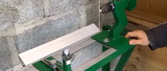
It is quite difficult to purchase a copy milling machine, so craftsmen make it with their own hands from scrap materials. Everything happens by trial and error. Therefore, experts advise first assembling a duplicate carver, and only then introducing it into mass production. As a rule, this stage is preceded by more than one serious adjustment and alteration.
Safety regulations
Since the tool is both electric and cutting, it requires careful operation and compliance with basic safety rules.
Safety guidelines include:
The device should be placed indoors in such a way that it is easily accessible.- The room itself should be well ventilated.
- Before turning it on, you need to make sure that the table surface is free of unnecessary objects and nothing interferes with the operation of the device.
- All fasteners, especially the cutter, must be securely fastened and not loose.
- The electric motor must be grounded and not damaged.
- Do not touch rotating shafts with your hands until they come to a complete stop.
- Any repair work is carried out only with the device turned off and the engine disconnected from the mains.
- You need to stand on a rubber mat while working.
- After half an hour of continuous operation, it is necessary to turn off the machine and allow the parts to cool.
Knowing and following simple safety precautions prevents injuries, cuts, bruises, and sometimes saves lives.
Milling and copying equipment: areas of application
Milling copying machines can process not only flat, but also three-dimensional parts. With their help, along with simple milling operations, you can perform engraving, repeat drawings, patterns and inscriptions. The design of the machine is quite simple, and any craftsman can make it.
Copy-milling machines allow you to process not only wooden parts, but also cast iron, steel and plastic workpieces, as well as products made of non-ferrous metals. This is ensured by high-quality tools made of high-speed steel and hard alloys. The copying machine allows you to mill not only straight, but also curved surfaces. In this case, the details are completely identical.
Making a pantograph
A milling cutter equipped with a pantograph allows you to repeat parallel lines of the workpiece during work. This procedure facilitates the production of shaped parts, various ornaments and patterns. In addition, using a pantograph you can make various inscriptions on metal and wooden plates.
It’s not difficult to make a homemade pantograph; you just need 4 ruler levers. Three such levers should be long, and one should be short. In addition, you will need to make several holes in them to mount the axles.
Copier milling.
The axles will be used to install the mechanism and attach the rod. The axial mechanism is a pin with a cap at the end. The copying part should resemble a compass element in which the stylus is attached. Such a rod part can be made from the tip of a plastic knitting needle. Such a tip will glide gently during operation and will not damage the original part.
You will also need an axis on which the entire mechanical part of the device will rest. It must be equipped with a heel that acts as a stop. The last or outer guide will act as a fastener for the entire structure using a special boss.
Such a boss should be made of an aluminum cylinder. In its lower part you need to attach 3 stings, which can be made from small furniture nails. These nails will be used to secure the base to the plate being processed.
Milling and copying equipment: design
The typical design of a copy-milling machine is completely simple. It consists of a work table and a guide system with clamps for attaching the router and copier.
Making a universal copy-milling machine at home is quite difficult, and there is no great need for it. For home use, equipment with highly specialized specialization is usually created.
Conclusion
Copying and milling equipment with a pantograph greatly facilitates and simplifies the production of wooden products with complex shapes and reliefs. Without them, such production would take much more time and labor.
After watching the video in this article, you will gain additional knowledge on the topic discussed, which is quite complex. If you don’t understand anything or have any questions, you can ask us in the comments to the article.
Manufacturing of copy milling machine: materials
To create a duplicate carver at home with your own hands, you should draw a basic sketch, which will become a guide to further actions. In addition, you need to stock up on some materials. This:
- Knee cemented polished shaft Ø 16 mm.
- Linear bearings in the amount of 2 pcs.
- Rail guides 900 mm long – 2 pcs. For ease of fastening, their length is taken as a multiple of 150.
- Split linear bearings in the amount of 4 pcs. It is advisable to use bearings with a clamping screw to adjust the tightness of the fit on the guide.
- Profile pipe 30×60 with a wall thickness of up to 3 mm.
- Metal plate 900 mm long and 100 mm wide.
- End posts in the amount of 2 pcs.
- Moving element in the form of a plate – 1 pc.
- Rocker arm for attaching the copier and router – 2 pcs. The length is chosen arbitrarily.
- Movable couplings – 2 pcs.
- Profile pipe 40×40 with a wall thickness of up to 3 mm.
- Crown clutch for turning the part and template.
Specification of parts for a homemade pantograph
| Part letter designation | the name of detail | Quantity | Dimensions in mm | ||
| Length | Width | Thickness | |||
| A | Large ruler | 3 | 406 | 20 | 5 |
| B | Ruler small | 1 | 220 | 20 | 5 |
| IN | Base (boss) | 1 | 60 | 40 | 30 |
| G | Bushing | 12 | 8 | — | Ø8 |
| D | Fixing axis | 1 | — | — | — |
| E | Axle support with heel | 1 | — | — | — |
| AND | Copier axis (original) | 2 | — | — | — |
| Z | Middle axis | 2 | — | — | — |
| AND | Pin clamp | 6 | — | — | 1,2-1,5 |
When all the parts are ready, assemble the pantograph mechanism. When assembling and adjusting parts, try to ensure ease of movement of all links of the mechanism, for which their rubbing surfaces can be slightly lubricated.
The final step in making a homemade pantograph with your own hands is to mark the holes on a ruler, according to which it will be easy to select the scale of enlargement (reduction) of the copy.
Be sure to check the correspondence of the markings with the resulting dimensions experimentally.
Home Latest publications, new on the site.
Repair and construction House and apartment, design and architecture, house projects. Reviews, advice.
Garden, vegetable garden, estate Gardening and horticulture, homestead farming.
Decorative and applied arts Wood carving, burning, chasing, weaving and much more.
Ideas for a DIY master, various original and useful homemade products.
Do-it-yourself furniture Self-made furniture, drawings, diagrams.
Making a copy-milling machine: tools
After this, you need to prepare a tool that will definitely be useful for assembling the machine structure. This:
- angle grinder;
- cutting and cleaning disc;
- welding machine;
- welding mask;
- petal disc or brush;
- self-tapping screws for fastening rail guides and moving elements;
- electric drill;
- screwdriver;
- measuring instruments: tape measure, caliper;
- center punch and scriber.
Completion of work
The next step is to assemble the copying mechanism for the router. To do this, you need to prepare the following components:
- 4 rulers;
- 8 brass bushings.
Rulers should be made of plexiglass or plastic, their thickness should be 4-5 mm. You can also use plexiglass as a material for making rulers. Next, the marking of these linear parts is carried out. This process should be approached very carefully, since the slightest error in dimensions can lead to incorrect operation of the pantograph.
Holes are drilled on the marked markings. In this case, their alignment must be maintained. To achieve this, you need to put all the rulers together and drill holes in them at the same time.
Making a copy-milling machine: step-by-step instructions
After everything is ready, the actual assembly of the copy-milling machine begins.
Step #1
It is necessary to cut two pieces 950 mm long from a 30×60 profile pipe to attach the rail guides. A margin of 50 mm is needed for installing limit switches in order to prevent linear bearings from slipping off.
Step #2
The 40×40 profile pipe needs to be cut into blanks for the base. Guided by the existing sketch, you need to cut two pieces of 1350 mm and two pieces of 900 mm.
Step #3
It is necessary to cut small racks from the same pipe. Their linear size depends on the height of the subsequently processed parts.
Step #4
Now you need to remove the rust from the pipes.
To do this, you can use a flap disc or brush. Important ! Before using the brush, pay attention to the maximum number of working revolutions on it and the grinder. The rotation speed on the brush must exceed the speed of the equipment.
Step #5
After this, we weld all the joints and clean the seams with a 6 mm thick cleaning wheel.
Step #6
Then it is necessary to ensure parallelism of the rail guides. To do this, you need to make the connection between the rack and the base of the rail guide detachable. It is necessary to take a washer according to the internal size of the rack, weld a nut to it and screw in the bolt. At this stage, the bolt is needed in order to install the nut and washer in the cavity of the stand pipe flush and in a strictly vertical position, and when welding it, do not damage the thread. This must be done with all four racks.
Step #7
Weld the posts to the base.
Step #8
At the base of the rail guide, at the junction with the racks, you need to drill holes: in the upper shelf for the bolt head, in the lower one for the thread.
Step #9
Install the rail guides on the base (30×60 pipe), pre-drilling holes, and secure with metal screws.
Step #10
Install the bases with rail guides and tighten with bolts.
Step #11
Check the parallelism of the guides. If it is missing, it is necessary to make adjustments by placing foil of different thicknesses on the racks under the guide.
Step #12
On the metal plate you need to mark and drill holes for attaching split linear bearings and end posts.
Step #13
After this, you need to make a movable element by welding 300 mm long rocker arms for the feeler gauge and router to a metal plate, then attach linear bearings to it.
Step #14
After this, the moving element must be placed on a polished shaft, along the edges of which the end posts must be installed.
Step #15
The entire structure must be installed on a metal plate 100 mm wide and the end posts must be secured with self-tapping screws.
Step #16
Then, split linear bearings must be installed on the metal plate on the bottom side.
Step #17
After this, the suspended structure is put on the rail guides with split bearings and the end switches are installed.
Step #18
Movable couplings are installed at the end of the rocker arms and a probe and a milling cutter are attached.
Step #19
In order for the workpiece and the part to rotate synchronously, it is necessary to connect them with couplings. A sprocket and crown are suitable for control. The copy milling machine is ready. The design achieved 5 degrees of freedom. Movement along the X axis is ensured by the movement of the structure along rail guides, movement along the Y axis is ensured by the movement of a moving element along a polished shaft, and movement along the Z axis is ensured by the movement of rocker arms.
Additionally, due to the movable couplings, the probe and the milling cutter can move left and right along the axis of the rocker arm, and it is possible to move the template and the workpiece simultaneously. This makes it possible to process parts of almost any shape.
How to make a pantograph with your own hands
Latest publications, new on the site. Repair and construction House and apartment, design and architecture, house projects. Reviews, advice. Garden, vegetable garden, estate Gardening and horticulture, homestead farming. Decorative and applied arts Wood carving, burning, embossing, weaving and much more. Ideas for a craftsman Do it yourself, various original and useful homemade products. Do-it-yourself furniture Self-made furniture , drawings, diagrams.
CNC on muscular traction (3d pantograph)
In the modern world, in the community of people who love to do things with their own hands and who do not shy away from technology, such a thing as a desktop CNC machine is extremely popular. Although these devices have become quite accessible, they still remain expensive. The cheapest Chinese option today will cost you 700-800 US money and it will probably not work right out of the box, but will require some effort to bring it to fruition. Making a CNC machine yourself can be cheaper, but usually requires access to various types of woodworking and metalworking equipment and the ability to use it to produce parts with high precision. But people are always looking for ways to achieve the goal with affordable means. In some tasks for CNC machines, namely when you need to repeat the same part many times, a pantograph, invented back in 1603 by Christoph Scheiner, can help - a device for copying maps, plans and other vector drawings. The classic pantograph consists of two vertices, one one of which is attached to a pointer handle, with the help of which the pattern to be copied is traced. The second contains a writing instrument, which, through a system of levers and hinges, repeats the movements of the first vertex, drawing a copy on the second sheet. Often, pantographs have a function of scaling the original image. A simple and ingenious idea. Now, how to copy a certain volumetric object? To do this, we need to add a Z-coordinate connection to the pantograph and replace the pencil with a drill, or better yet, a high-speed spindle, and we will get a 3D pantograph. Machines for copying wooden products on this principle are produced, for example, by the American company Gemini, but the prices for them are such that With this money you can buy a good CNC machine from China. Therefore, it is more interesting what the DIY community has achieved in this area. Frank Ford makes acoustic guitars. At the same time, he has to make many identical guitar parts, such as string holders. Tired of doing it manually, but not wanting to bother with buying and setting up a CNC, he made a duplicator for himself. Because High copying accuracy was important to him; his instrument was made entirely of metal. The probe used to remove the mold and the spindle are fixed on a common frame, which moves only along the Z axis. Movement along the X and Y axes is carried out using a table on which the workpieces are fixed. Another original thing in its design is that it uses a pneumatic drive operating at 40,000 rpm as a spindle. However, although this is a homemade, it is still an expensive version of the 3D pantograph. There are also cheaper ones. For example, Adran, dreaming of his own CNC machine, but not having the funds for it. I built myself a duplicator from a Dremel drill, three metal guides and standard-sized wooden strips from the store. A regular screwdriver is used as a probe. Its design can be easily repeated, because he posted the drawings and all the manufacturing stages on the Instructables website. However, a hand drill is not the most successful tool for such work; its material removal speed is too low. Here Matthias Wandel from Canada used a manual milling cutter in his 3D pantograph. Which gave him enough power to quickly copy objects in the tree. As an example of working with such a duplicator, here is his video, where he makes a copy of the shape of an old rotary telephone (English). Its design can also be repeated, because he has posted plans and manufacturing instructions on his website, Woodgears.ca. Even if you are not fluent in English, you can easily understand the whole process from numerous photographs. If the topic of 3D pantographs interests you, then on English-language resources examples of such devices can be found under the tags: carving duplicator, duplicarver, pantorouter. Let's look carefully around us, and we will see how many identical objects are around. They seem to be similar to each other, but differ in size, color... Such similarity is called similarity, i.e. a concept that characterizes the same shape of objects, regardless of their size. There are a great many similar figures around us. Similarity surrounds us. Here are some examples from our life. Many drawings in children's coloring books are similar to each other. In order to draw them, you and I can use a device called a pantograph. Today we will make a simple pantograph ourselves from cocktail tubes. Take:
- 4 cocktail straws (without corrugation)
- 4 sewing pins
- Narrow tape
- Scissors
- 2 markers
How to make a pantograph for drawing
- We connect the tubes with a pin at the ends (the pin is the axis of rotation)
- Take the third tube, bend it in half, and attach it with pins to the middle of the first two tubes.
- Cut a piece 3 cm long from the fourth tube and tape it to the fold of the third tube (we will insert a felt-tip pen or pencil here).
- The remainder has 4 tubes 3 cm long, cut along the end (as in the picture).
- They wrapped the cut ends around a felt-tip pen and wrapped it with tape.
- Insert a pin into the first tube (the free end).
- Make a cut in the free end of the second tube to a length of 2 cm. We put a 4th tube with a felt-tip pen on the cut end of the second tube.
- Thus, we lengthened the pantograph arm.
- We stick a pin-retainer in 1 tube into the base. Insert a felt-tip pen into the holder of 3 tubes. And we draw! We see that the felt-tip pen on the long arm (4 tubes) draws a similar figure, only larger in size.
Why do you need to draw with felt-tip pens? Yes, because the structure turned out to be quite fragile and requires a minimum of effort. And with felt-tip pens, as we know, I draw quite easily, without requiring pressure. But the word pantograph has many meanings. We have made a device for enlarging or reducing drawings. These are also pantographs: a manipulator for loading and unloading operations (“mechanical arm”). And in a children’s toy, the mechanism of movement of a frog is called a pantograph. And a current collector on electric locomotives, electric trains and trams, which serves to collect current from contact network is also a pantograph.
Pantograph for a router: principle of operation
The schematic diagram of a pantograph looks quite simple. It is a square divided in half. All joints are hinged, so all sides are movable, and the square easily turns into a rhombus when impacted. The zero point, located in one of the corners of the square, is fixed rigidly. Relatively, its design can be modified, turning into a rhombus. A cutting tool is installed in the middle of the square. A copier is fixed diagonally in the opposite corner of the square. The distance from the zero point to the cutter is a certain value A, and to the copier 2A. This gives a 2:1 scale. The linear size of the long and short sides of the pantograph should also differ from each other by 2 times.
Homemade pantograph
Quite often it is necessary to enlarge (or reduce) some drawing, drawing or diagram several times. For example, you liked the burning patterns in the magazine. But in the magazine they are usually given in a reduced form, so you have to enlarge them to the required size yourself, either manually using the “cell method” or using instruments: an episcope or a pantograph.
Making an episcope yourself has already been discussed on the website. Now let's look at the pantograph.
Pantograph (the name comes from two Greek words (pantos) - everything and qrapho - I write) - a device in the form of a sliding articulated parallelogram for redrawing pictures, drawings, diagrams in a different (increased or reduced scale). The main advantages of this device are the simplicity of the design and the fairly high “accuracy” of the copied image. Unfortunately, the pantograph has not yet found due recognition among amateur artists and other handy admirers of decorative and applied arts.
It is now very difficult to find commercially produced pantographs on sale. In addition, the range of such pantographs is relatively small, and they are made of metal, which does not make the device convenient enough. So God himself ordered to make for himself a pantograph with long wooden rulers.
As already mentioned, the pantograph has the form of a sliding parallelogram and consists of four wooden planks (rulers), fastened together using hinges so that the rulers can move and move apart like an accordion (Fig. 1). As can be seen from the figure, at the ends of the pantograph bars there is a needle (pole), a mark (pin) and a pencil. When working, the needle is fixed at some point on the table, the mark is drawn along a given contour, and a pencil draws a copy of this contour, but on a given scale.
Rice. 1. General view of the pantograph: 1 – needle; 2 – spire; 3 – pencil
First of all, for the pantograph it is necessary to make four rulers 630 mm long, 15 mm wide and 4 mm thick. It is better to cut such rulers from thin slats, but you can also cut them from plywood. On all rulers, the working part is first marked, for which 15 mm are set aside from the ends of the ruler. Thus, there will be a distance of 600 mm between the marks, which will be the working part of the ruler. We will denote the beginning of the working part of the ruler by the letter N, and the end by the letter K. Of course, we choose the beginning and end of the working part arbitrarily.
Next, we will mark on the working part of each ruler the centers of the holes that we will need when adjusting the pantograph to one or another magnification. Let's assume that for our work we need to enlarge the original by 1.25; 1.5; 2; 3; 4; 5; 6 and 7 times. And to get, for example, the center of a hole with a magnification factor of 1.25, you need to divide the length of the working part by 1.25 and put the resulting size on a ruler, taking point H as the reference point. That is, the center of the desired hole will be at a distance of 480 mm from the beginning of the working part. In the same way, from point H, we determine the distance of the centers of the holes to increase the original by 1.25; 2; 3 times and so on (Fig. 2). Having marked the position of the centers on the rulers, at each mark we write a number that will correspond to the degree of magnification of the drawing.
Rice. 2. Location on the ruler of the centers of the holes, with the help of which one or another magnification of the pantograph is ensured (numbers on the rulers are magnification factors)
Using the resulting markings, we drill holes in the rulers for the bolts that are supposed to connect the rulers. Bolts with M3 or M4 threads are most suitable for these purposes; accordingly, holes for them are needed with a diameter of 3 or 4 mm. But we make the outer holes at points H and K with a diameter of 5.6 mm, that is, the diameter of the shells from a small-caliber rifle, which we will use to attach a needle, a mark and a pencil to them. Next, using sleeves, we hinge the rulers in pairs, aligning the end of one ruler with the beginning of the other (Fig. 3, a), after which we flare the open ends of the sleeves. All that remains is to select the magnification factor and connect the pairs of rulers, installing the bolts in the holes with the required index. Thus, the pantograph shown in Fig. 3, b, ready to enlarge the original 4 times.
Rice. 3. This is how the pantograph is assembled: a – two pairs of rulers; b – the pantograph is ready for work (magnification factor – 4); P, O and P – places for attaching a needle, pin and pencil, respectively
At point P (Fig. 3, b) there is a pantograph pole (needle), at point O (the point where the pair of rulers are hinged) there is a marker, at point P there is a pencil. If the ends of the rulers were connected using sleeves, attaching a needle, a mark and a pencil to the pantograph is very simple. To install the needle, you need to tightly insert a stick (wooden plug) into the appropriate sleeve, and then hammer a piece of a thick needle into the center of which with the blunt end. But you can fix this fragment of a needle in a sleeve by pouring molten tin or lead into it.
A pointed stick is suitable as a marker; it is not at all difficult to secure it in the desired sleeve. The end of the stick should protrude from the sleeve by about 1 cm. If a long bolt is used instead of the sleeve, it is oriented with the head up, secured with a nut, and the end is sharpened with a file. Installing a pencil into the sleeve is also not a problem.
We emphasize once again that when making a pantograph, precise marking of the hole is necessary, as well as full correspondence of the diameter of the hole in the ruler to the diameter of the bolt. Only then can a pantograph be used to achieve sufficient accuracy even when copying very complex designs.
How do they work with a pantograph? First of all, the pole (needle) of the pantograph is attached to a certain point on the table. The drawing from which you want to make a copy is placed where the spire is located, and a blank sheet of paper is under the pencil. Next, we draw the pin along all the lines of the drawing, while the pencil automatically draws an enlarged drawing on the paper. And if you need to depict the drawing in a reduced form, you will have to use a pin and a pencil in places, which is not at all difficult if you have sleeves.
Usually, when working with a pantograph, the hand of the artist guides the pin along the lines of the pattern. In this case, you will have to attach a weight (nut, lead plate) to the ruler next to the pencil so that the pencil is pressed against the paper. But you can copy in another way. Namely, move your hand not with a pin, but with a pencil, while ensuring that the marker moves correctly along the lines of the pattern. In this case, the weight on the ruler, of course, is not needed.
Pantograph for a router: materials
In order to make a pantograph with your own hands, you will need the following materials:
- Square metal profile 12×12
- Bearing 180201.
- Bushings for the outer race of the bearing.
- Pins according to the internal size of the bearing and M12 thread.
- Nut M12.
- Bolts M6×45
- Nuts M6.
- Bushing for securing the copier.
- Profile pipe 40×40
- Hinge of a metal-plastic window.
- Dye.
- Masking tape.
- Metal plate.
- Screw for fixing the copier.
One Reply to “Pantograph for router”
Comments are closed.
- All in all
- Workshop
- Furniture In the bathhouse
- To the living room
- To the nursery
- To the office
- To the kitchen
- To the bedroom
- Soft
- Sadovaya
- Garlic
- Chickens
- Toys
- Finishing
- Drill
- Materials
Tags
Recent Entries
- Tool breakdowns, search for spare parts and self-repair
- Wood in the interior: warm and cozy
- What is an edge router?
- Milling cutters PIT PER12-C, Diold MEF-2.1, VORTEX FM-1900, STERN Austria ER2050 – twins and brothers?
- Review of the Festool OF 1400 hand router. Is it worth the money?
Recent comments
- Ratmir on How to make a jointer from an electric planer
- Tool breakdowns, search for spare parts and self-repair to the entry Milling cutters PIT PER12-C, Diold MEF-2.1, VORTEX FM-1900, STERN Austria ER2050 - twins and brothers?
- Wood in the interior: warm and cozy to the post Do-it-yourself children's table made of solid wood
- Review of the Festool OF 1400 hand router. Is it worth the money? back to entry Device for milling sockets and grooves
- Slot milling attachment for recording Festool OF 1400 manual router review. Is it worth the money?
How we build a house
Attention! 15% discount on repair items. Using promo code GD181215REM. Applies to power tools, measuring equipment, pneumatic tools, power equipment, machine tools, hand tools, construction equipment and supplies, electrical installation products.
Pantograph for a router: step-by-step instructions for making it yourself
Let's proceed to the actual production of the pantograph.
Stage No. 1. Workpiece cutting
It is necessary to mark and cut the square profile according to the calculated dimensions. For convenience, you can use masking tape and a metal plate. The tape will allow for clear markings, and the plate will help make an even and high-quality cut. The blanks for the platform for the router must be cut at a right angle, and the sections of the profile for the connecting rods must be beveled for maximum fit of the bearing sleeve.
Stage No. 2. Drilling technological holes
All workpieces must be chamfered and holes Ø 6.2 mm drilled for further connection into the structure.
Stage No. 3. Welding the platform for the router
After this, you need to weld the platform for the router.
Stage No. 4. Manufacturing of connecting rods
It is necessary to make something like a jig on the board and firmly fasten all the parts to be welded. To do this, a hole is drilled in the board, and the bearing in the bushing is clamped with a bolt, the square profiles of the connecting rods are secured with clamps. First you need to insert two washers between them and fasten them with bolts. After this, all joints of the structure are scalded and cleaned. Then you need to cut the bearing sleeve between the square profiles on each connecting rod. M6 bolts, washers and bearings must be removed. It is necessary to weld a mount for the router onto the frame, and an extension for scaling onto the short connecting rod at the point opposite the zero point. The connecting rods can be painted to give an aesthetic appearance.
Stage No. 5. Making a unit for attaching a copier
Now you need to machine two bushings with an internal diameter similar to the size of the copier. Drill a hole on the side and cut a thread to install the screw that secures the copier. After this, you need to cut two pieces of 12x12 squares 20-30 mm long and weld them on the side between the bushings. The size between squares should be 12 mm.
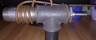
Stage No. 6. Manufacturing of the bearing lifting mechanism
It is necessary to manufacture a bearing lifting unit. To do this, the zero point finger must be welded onto a piece of 12×12 profile and secured to a 40×40 profile pipe using a loop from a metal-plastic window. The profile pipe will serve as a place for attaching the pantograph to the table with a clamp.
Stage No. 7. Pantograph assembly
The bearings must be installed in the bushings and secured securely by tightening the square profiles of the connecting rods with M6 bolts. Using your fingers, you need to assemble the connecting rods into a single structure. Secure the pantograph to the table with a clamp and install the router. The device is ready for use.
The operating principle of a pantograph device for redrawing plans and drawings
Let's look carefully around us and we will see how many identical objects there are around. They seem similar to each other, but differ in size, color...
Such similarity is called similarity, i.e. a concept that characterizes the same shape of objects, regardless of their size. There are a great many similar figures around us. Similarity surrounds us. Here are some examples from our life.
Many drawings in children's coloring books are similar to each other.
In order to draw them, you and I can use a device called a pantograph.
A milling cutter equipped with a pantograph allows you to repeat parallel lines of the workpiece during work.
This procedure facilitates the production of shaped parts, various ornaments and patterns.
In addition, using a pantograph you can make various inscriptions on metal and wooden plates.
It’s not difficult to make a homemade pantograph; you just need 4 ruler levers. Three such levers should be long, and one should be short. In addition, you will need to make several holes in them to mount the axles.
The axles will be used to install the mechanism and attach the rod. The axial mechanism is a pin with a cap at the end.
The copying part should resemble a compass element in which the stylus is attached. Such a rod part can be made from the tip of a plastic knitting needle.
Such a tip will glide gently during operation and will not damage the original part.
You will also need an axis on which the entire mechanical part of the device will rest. It must be equipped with a heel that acts as a stop. The last or outer guide will act as a fastener for the entire structure using a special boss.
Such a boss should be made of an aluminum cylinder. In its lower part you need to attach 3 stings, which can be made from small furniture nails. These nails will be used to secure the base to the plate being processed.
Completion of work
The next step is to assemble the copying mechanism for the router. To do this, you need to prepare the following components:
- 4 rulers;
- 8 brass bushings.
Rulers should be made of plexiglass or plastic, their thickness should be 4-5 mm. You can also use plexiglass as a material for making rulers.
Next, the marking of these linear parts is carried out.
This process should be approached very carefully, since the slightest error in dimensions can lead to incorrect operation of the pantograph.
Holes are drilled on the marked markings. In this case, their alignment must be maintained. To achieve this, you need to put all the rulers together and drill holes in them at the same time.
Then you need to insert brass bushings into the prepared holes. When installing them, a slight tension should be observed: this will help the bushings to stay more tightly in the rulers.
In order to secure the axial parts in the bushings, you need to make special clamps.
They can be made from hardened steel wire, the diameter of which should be 1-1.5 mm.
Then the boss is assembled. Blind holes are made in its lower part, which can be punched with a core. The nails must be installed in such a way that they protrude from the body of the boss by 2-3 mm.
Having prepared all the necessary parts of the pantograph, they are assembled.
During this process, you need to ensure that all moving parts move smoothly and easily.
In this case, all prepared holes should be marked. According to this marking, you can scale the manufactured copy of the part.
moiinstrumenty.ru
Make it for school
Pantograph
This simple drawing device can be used to redraw plans, drawings, geographical maps or decorative elements, increasing or decreasing their scale by 1.5, 2 and 3 times.
The device is a parallelogram formed by four planks - two long and two short, made of well-planed hardwood (oak, beech or birch).
The planks are connected to each other with screws and nuts. Pay attention to the screw (view B) - it is of an unusual type.
If the device is used to obtain a copy on an enlarged scale, a guide pin is fixed in node B - it can be a blunt nail clamped into a collet pencil, and a regular pencil, felt-tip pen or ballpoint pen is fixed in node B.
By tracing the lines of the original with a pin, we will obtain a copy of the specified magnification scale on paper. To obtain a copy in a reduced form, the guide pin and the writing instrument are swapped.
To select the scale, holes are provided in the long and short bars and a digital designation is entered, the ratio of reduction or increase.
Clamping pins are most easily made from a piece of rubber in the form of flat washers. The holes in the washers should be cut so that the collet pencil and writing instrument fit tightly into it.
A clamp is provided to secure the device to the workbench. It must be made from a steel plate 1.5 mm thick.
To prevent the clamp from scratching the table top, cut a 2 mm thick rubber gasket under it. There is a hole on the upper plane of the clamp into which the pantograph axis is inserted.
As you can see, there is no bearing here. Therefore, to reduce friction between parts, install washers.
A. SALNIKOV
In the figure, the numbers indicate: 1 - clamp, 2 - rubber gasket, 3 - table cover, 4 - long strap, 5 - short strip and 6 - rubber clamps.
12
zhurnalko.net
What is copy-milling equipment
This equipment is unique because... with its relatively simple design, it is capable of copying complex products, even fine handmade ones.
In fact, the unit was designed for milling curved elements:
- This is done by copying using templates. They allow you to perform the operation as accurately as possible, without the use of manual work. This property of the unit guarantees that the manufactured elements will be identical in size and shape.
- You can use one sample for all blanks or use ready-made products as a template.
- When such parameters are not enough, it is possible to significantly increase the accuracy of the machine.
Note! The instructions recommend equipping it with a special copying device for this purpose. It is called a “pantograph” and serves to accurately communicate the movement of the copying unit (head) to the main device that processes the part.
When a template has many fine, elegant details, a pantograph machine is indispensable.
Unit design
Copy-milling units make it possible to process reliefs or profiles:
- The workpieces are processed with a special tool - a milling cutter made of hard alloys.
- It repeats in full the movements of the copier, which reproduces the outlines of the template.
- The copier is equipped with an electronic or mechanical connection that has a tracking system and is responsible for the trajectory of the tool.
- The copier can be a flat or three-dimensional sample, as well as a contour diagram or a reference model.
- In this case, a special probe registers the contours of the part. This data is then reported to the tool.
- In the most modern machines, the probe is replaced by a photocell, which has increased accuracy.
Note! The pantograph plays a vital role in the described units. It is equipped with a special guide “finger”.
It moves along the copier, while determining the geometric parameters of the sample with maximum accuracy. The final size of the resulting copy depends on the proportions of the pantograph’s “shoulders.”
Duplicarver machine
The most popular brand of copy milling machines are the Duplicarver units:
- Its cutting tool is a cutter made of hard alloys, which reproduces the contour or surface of the copier on the workpiece.
- It has a mechanical, hydraulic or pneumatic connection with a tracking system that determines the direction of movement of the cutter. The cutter acts on the reinforcing device and affects the actuator.
- The copier can be a flat or spatial template, a contour diagram, or a reference sample. The copying device can be a finger, a photocell, a probe or a roller. This unit and the workpiece are placed on a rotating work table.
- The executive body of the unit can be a solenoid, differential, screw, electromagnetic clutch, spool. The amplification units use a hydraulic, electro-optical or electromagnetic relay.
- The speed of movement of the tracking device determines the level of accuracy of the profile (up to 0.02 mm), as well as the degree of roughness of the part.
- The machine is driven by an electric motor and a hydraulic power cylinder.
- The pantograph, which makes it possible to repeat products on a given scale, has a tool spindle and an axis of rotation, as well as a guide pin. It is placed on an axis and moves along the copier.
- During this movement, the spindle on the part describes the desired geometric configuration. The pantograph, thanks to the proportion of its shoulders, determines the scale of copying.
What is copy-milling equipment
The pantograph is the most important element of the machine.
This equipment is unique because... with its relatively simple design, it is capable of copying complex products, even fine handmade ones.
In fact, the unit was designed for milling curved elements:
- This is done by copying using templates. They allow you to perform the operation as accurately as possible, without the use of manual work. This property of the unit guarantees that the manufactured elements will be identical in size and shape.
- You can use one sample for all blanks or use ready-made products as a template.
- When such parameters are not enough, it is possible to significantly increase the accuracy of the machine.
Note! The instructions recommend equipping it with a special copying device for this purpose.
It is called a “pantograph” and serves to accurately communicate the movement of the copying unit (head) to the main device that processes the part.
When a template has many fine, elegant details, a pantograph machine is indispensable.
Types of copy-milling devices
Stationary automatic unit.
At the moment, manufacturers produce copy-milling units that differ in many characteristics. Accordingly, the price of the equipment is different.
The following machines are produced according to the type of drive:
- with mechanized feed;
- photocopying;
- with hydraulic feed;
- electrified.
Based on the level of functionality and equipment, the following are distinguished:
- copying units with a two- or three-dimensional pantograph;
- universal equipment with a pantograph located vertically on a rotating arm;
- single- and multi-spindle devices with a rectangular or round work table.
Manual machine.
The machines also differ in size and degree of automation:
- The cheapest is a desktop-type manual mini machine with a mechanical clamp.
- A full-fledged automated machine is more functional. It is equipped with a pneumatic clamp.
- The stationary unit is the most versatile. It has full automation, pneumatic clamping and a three-spindle attachment.
It should be noted that all of these devices can be equipped with computer numerical control (CNC).
Features of the units
Below are the categories of copy-milling devices, varying in the pressing of the part and the degree of automation:
- A manual or tabletop unit with mechanical pressing of the profile makes it possible to make holes of various shapes using a template.
- The automatic analogue with pneumatic clamping is capable of processing large parts. Can be equipped with CNC.
- Automatic device with pneumatic pressing of profiles, equipped with a three-spindle attachment. The latter makes it possible to drill triple holes. Other machines do not have this capability. Can also be equipped with CNC.
Which one should I do?
Dozens of different milling operations and at least a dozen types of machines for them are used to process materials. At home, not all of their designs can be repeated by beginners and intermediate craftsmen. 2- and 3-axis CNC machines (2D and 3D wood milling machines) are not discussed in this article. It is possible to make a 2D or 3D milling machine yourself (item 1 in the figure below), but already having quite a lot of experience working on a simple machine, a significant volume of orders and an urgent need for a sharp increase in labor productivity. At the same time, you will have to master programming microcontrollers, because... finished samples are designed for a machine of a very specific design; There will also be significant costs for stepper motors and precision drive parts.
Types of homemade wood milling machines
To begin with, at home, you can make a homemade milling machine using any of the following. varieties:
- Horizontal (item 2 in the figure).
- Vertical (item 3).
- Flat copy machine with pantograph (2D duplicator, item 4).
- Machine for volumetric copying (3D duplicator, item 5).
Tool…
The choice of a machine of one type or another is determined, of course, by the work operations most used by the master. To specify their nomenclature, you must first decide which working parts (cutters) you will most need. Most of them are applicable in both horizontal and vertical machines.
Types of wood cutters
Mounted cutters (item 1 in the figure) are processed primarily. straight edges of the boards: grooves and ridges (including shaped ones) are cut out to their full length, and a chamfer is applied. The spindle assembly of the machine for attachment cutters (see below) is structurally the simplest; its parts can be turned by a 3rd class turner. The required drive power for a processing depth of up to 60 mm is from 1.5 kW. The quality of the material is almost any, ranging from raw material straight from the sawmill. A vertical wood router is most suitable for attachment cutters, see for example. Below is a video in 4 parts:
Video: homemade wood milling machine with attachment cutters
There are many more varieties of milling cutters with a cylindrical shank (landing, seating), because their functionality is wider. But for such a cutter it will be necessary to machine a spindle attachment with a Morse taper for a clamping chuck; It is also possible to use ready-made spindle units from a drilling machine.
End mills, e.g. Forstner cutter (item 2 in the figure above) is a specialized tool; They choose round holes with a flat bottom in thin boards with a decorative coating that cannot be damaged. Have you ever hung doors on furniture? The holes for their loops were chosen using a Forstner cutter. The quality of the material is no worse than straight-layered wood of the 1st grade, chamber dried. Required drive power from 150 W. They work with end mills only on a vertical machine or, with a certain skill, manually.
Note: using a Forstner cutter in a 170 W screwdriver to select holes D32 for door hinges in furniture chipboard 16 mm thick is quite possible, I did it myself.
End (finger) milling cutter, pos. 3, can be threaded into both horizontal and vertical spindles. Using end mills, blind grooves are selected (not the entire length of the board) and tenons are cut for tongue-and-groove joinery joints. It is more convenient to work with an end mill on a horizontal machine. On a vertical surface, it can be used to select long grooves (grooves) of a rectangular profile on the surfaces of boards and beams. Tapered end mills (item 4) are also a specialized tool for preparing parts for dovetail joints. They work with conical end mills only on a vertical machine. For both of them, the required drive power for a processing depth of up to 80-100 mm is from 1 kW. The quality of the material is from commercial wood of the 2nd grade, air dried (from a timber exchange).
End shaped (curly) cutters, pos. 5, also a specialized, but highly sought after tool. They apply molding (including on curved edges) and select shaped grooves (decorative grooves) of any configuration in the faces of the boards. Drive power from 1.2-1.5 kW; The quality requirements for the material are the same as for end mills. To process edges, the shaped cutter can be threaded into either a horizontal or vertical spindle; for working on layers only in a vertical position.
Roller-cone cutters (burrs, item 6) can also be used to select shaped grooves and create a groove on both a horizontal and vertical machine, but in general they are a special tool for copy milling machines. The requirements for the quality of the material are high, as for end mills, but the drive power in the copier can be from 250-300 W.
And, finally, using a circular cutter (item 7) in a vertical milling or drilling machine, round holes of large diameter are cut out in almost any material that is not overly thick (including sheet metal). Required drive power per hole D200 in 60 mm thick oak board approx. 2-2.5 kW.
...and his presentation
Milling can be done in two ways: up and down, see fig. below. As for wood, ordinary straight-layered wood (especially one that is not of very high quality air-dried) is milled only along the way, otherwise the milling cutter can even split and/or fray the workpiece. But in this case, with an excessive feed rate, there is a considerable probability of the workpiece being pulled away by the cutter and damage to the processing profile. Removing dust, sawdust and shavings from the working area (and this is a serious problem) on a vertical milling machine during down milling is difficult, because The dust collector (see below) has to be placed in the field of view in front of the cutter and it obscures the working area.
Up and down milling methods
Note: on a horizontal milling machine there are no problems with removing processing waste during down milling, because dust (sawdust) then flies down, and the dust collector socket can be placed directly on the machine plate (see item 2 in the figure at the beginning and below).
Up milling gives better precision and cleanliness of processing, but only on sufficiently high-quality and homogeneous materials. From wood - on solid, fine-grained wood, chamber dried. Removing processing waste on a vertical milling machine is easier, but on a horizontal one it is difficult - dust and sawdust fly upward. The removal of the workpiece is almost impossible, but there is a danger of it being bitten by the cutter. A well-behaved profile can often be modified; a bitten and broken piece is an unconditional defect.
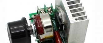
Motor
Based on the above, it is optimal to make a do-it-yourself milling machine with a drive with a power of 1.5-2 kW. The reason is that motors up to this power are produced, incl. asynchronous with capacitor starting for voltage 220 V 50 Hz. They can be plugged into a regular household outlet, and switching the direction of rotation is a child's task for an amateur electrician; rotation speed is 700-2850 rpm, which is suitable for milling. It is also possible to use an electric motor of the same type from a washing machine; in this case, it becomes possible to switch the rotation speed (in asynchronous washing machine motors there are different windings for this). A 2 kW motor will provide a processing depth of up to 80-100 mm; if a larger one is required, you will have to install a three-phase motor at 380 V 50 Hz from 3 kW into the machine, see for example. video clip:
Video: homemade vertical milling machine for wood
Note: commutator electric motors of 1.5-2 kW 220 V 50/60 Hz (for example, from another washing machine or vacuum cleaner) are of little use for driving a milling machine - due to their excessively soft external characteristics, the cutter may get stuck in the wood if the workpiece is not manually fed, tear and rag it (if it’s damp).
Making it vertical
A vertical wood milling machine has much greater functionality and provides better quality of material processing than a horizontal one. It is vertical milling machines that are mostly built by home-made amateurs. However, the problem of combating vibrations in a vertical milling machine is much more acute. If in a horizontal router vibrations through the base of the spindle unit are given priority. down and are effectively damped, being reflected in the thickness of the material, then in a vertical machine, elastic waves in the machine plate propagate mainly to the sides. In this case, their inerference is possible and the emergence of standing waves with antinodes (foci) of such a size that the workpiece is thrown away from the cutter. Therefore, one of the main tasks of designing a homemade vertical router is to suppress machine vibrations.
Structural diagram
Vertical milling machines with a bottom drive of a free (fixed only from below) cutter are least susceptible to vibration. The working body is mounted directly on the motor shaft. The entire drive is made as vibration-resistant as possible. Under the influence of the beating of the cutter on irregularities in the workpiece, the drive staggers and sways. At the same time, a noticeable transverse (vertical) component appears in the waves of elasticity, effectively absorbed by the frame, and a heavy motor with a massive, rapidly rotating rotor plays the role of an inertial absorber of mechanical vibrations.
The structure of industrial and homemade vertical wood milling machines is shown in the figure:
Construction of industrial and homemade vertical milling machines for wood with bottom drive
Their main difference is in the folding (lifting) stop 7. Since amateur designs do not use drives of 5 kW or more with high-performance cutters, the folding stop is replaced by a lifting one, which prevents the workpiece from being squeezed upward from the cutter. Also, for an amateur machine, an adapter attachment with a Morse taper on the motor shaft is machined to order, the same as for a homemade drilling machine. A standard clamping chuck for a cylindrical shank is installed on the cone. In this design, it is also possible to use mounted cutters: adapters for them with a cylindrical shank are commercially available or are included in the set of cutters. The most important structural components of such a machine are:
- The base plate is the main damper of longitudinal (horizontal) elastic waves in the machine;
- Vibration damping drive board;
- Comb stops (stop) – dampen vertical vibrations of the workpiece;
- Static side stop - ensures correct feeding of the workpiece, and in a homemade machine also some adjustment of the cutter output (horizontal processing depth);
- Dust collector – removes processing waste to the dust collector.
The latter is absolutely necessary when milling, because The cutter produces several times more wood dust, sawdust and shavings than is produced during sawing. The base plate is most often made integral with the vibration damping suspension of the drive. The cabinet (bed) can be anything, as long as the slab and other parts do not fall down.
Drive plate and suspension
Installing the drive of a homemade wood milling machine into the base plate
The window (opening) for hanging the drive from the machine plate is most often cut out square (see figure on the right), this is easier at home. But the machine will tremble much less during operation if the window for the drive is made round. In any case, the motor should not directly touch the plate (again, see the figure on the right), otherwise, instead of dampening vibrations, they will be amplified.
The best materials for the plate and drive board are fiber-laminated plastics: textolite, fiberglass with a thickness of 12-15 mm; the thicker the better. Hardboard and other massive plastics are less suitable: they dampen vibrations well, but over time they warp when heated by the motor and the machine loses accuracy. Getinax and other thermosetting laminates are unsuitable: they delaminate very quickly due to vibrations.
However, it is neither possible nor practical to make the entire slab as one piece: it is difficult, expensive, and the vibrations of the drive itself will be freely transmitted to the slab. You only need to make the motor board from plastic, and the slab from plywood impregnated with a vibration-absorbing composition and glued together, and low-grade construction and packaging material will do. The slab must be re-glued with at least 5 sheets so that the fibers of the outer layers of adjacent layers are oriented mutually perpendicular.
The cutting diagram for a standard sheet of plywood 1550x1550x4 mm into sheets for the base plate of a wood milling machine is given on the left in Fig. Sheets for the horizontal router plate are cut out without windows for the motor, but with a dust collector socket (see above and below). Slab size up to 750x500 mm. A 50 mm flash along the contour of the sheet is needed to cut off low-quality material at the edges.
Scheme for cutting a sheet of plywood and a device for suspending the drive of a homemade wood milling machine
The sheet is first generously impregnated 2-3 times on each side with eco-construction soil (water-polymer emulsion), it perfectly dampens vibrations. The interval between impregnations is at least 3.5 hours. Then the sheet is cut out and a plastic film is spread on the floor (not PVC, it will stick!). Sheet No. 1 is placed on the film and with a brush (preferably a “shaggy” paint roller) a thin, even layer of mounting (reinforced) PVA is applied to it; the same layer is placed on the adjacent side of sheet No. 2. Immediately after applying the glue, the brush (roller and its tray) are thrown into a bucket of water, and after all gluing is completed, they are washed in water.
Before folding, the sheets are kept for 15-20 minutes (or according to the instructions on the glue package), folded and straightened, without being separated, so that the edges of the drive window meet exactly. Then sheets No. 3, 4 and 5 are glued in the same way. The entire package is covered with film and loaded over the entire area with a dispersed load of 30-40 kg (it is best to pile on more books or magazine files). Dry for at least 3 days at room temperature: mounting PVA is durable, its adhesive layer is viscous and perfectly absorbs vibrations, but takes a long time to dry to full strength.
The design of the motor suspension is shown in the section on the right in Fig. A gap of 0.5-1 mm should be left between the motor board and the machine plate. There is no need to clean sawdust out of it: it will serve as an additional side vibration-damping cushion. It is advisable to find a motor with mounting feet that protrude beyond the dimensions of the housing: then it will be possible to install (not manually) the offset of the cutter upward. To set the cutter in height, the motor mounting screws are taken long, and the stem itself is set by putting steel washers on them, between the rubber suspension cushion and the motor body, alternately with gaskets made from the same tube-type truck tire.
The slab with the hanger is checked for workmanship with a pencil. If you place it sticking out 5 cm from the edge of the suspension board, then when the engine is on at idle, the pencil should not fall.
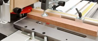
Stop and dust collector
For a drawing of a simple but good static side stop with a dust collector socket, see the following. rice. The material is re-glued plywood from the same sheet. Holes for the comb and lifting stops are drilled in 3-5 pieces: the first 50 mm from the edges of the cutout for the cutter (rectangular); the rest after 25-30 mm. The position of the stops is selected depending on the size of the workpiece and the quality of its material. The lateral offset of the cutter is adjusted within small limits by turning the stop and securing it with a clamp.
Drawing of a side support with a dust collector for a homemade wood milling machine
Dust collector
Dust collector device for a homemade wood milling machine
Since there is no industrial pneumatic system with air extraction at home, milling dust has to be sucked out with a household vacuum cleaner. If you connect it directly to the dust collector pipe, the required expensive household appliance will soon fail. An expensive, well-cleaning vacuum cleaner with a hydraulic separator will most likely immediately. So, in addition to a dust collector, a homemade wood router also requires a dust collector, through which the vacuum cleaner is connected.
The design of a dust collector for a milling machine is shown in Fig. on right. The container is round, from 10-15 l (preferably from 20 l). The ideal option is a household bucket with a tight lid, fitted with a seal and equipped with snap-on latches (both can be done with your own hands).
Inlet pipe – diameter approx. 20 mm (inside). Its end is beveled 45 degrees and rotated 20-30 degrees outward; installed 15-20 mm from the side of the vessel (counting from the outer edge of the pipe). The exhaust pipe is wider, approx. 30 mm inside; is installed exactly along the vertical axis of the container. Its selected end is narrowed to 15-20 mm (the taper is not critical). Everything works together like a cyclone, and the air entering the vacuum cleaner is clean enough not to spoil the device.
Note: an additional advantage of the dust collector is that the dust from it is an excellent filler for high-quality wood putty. For this, the dust is mixed with PVA (3-4):1 by volume.
Comb
A drawing of the comb stop of a wood milling machine is given in the following. rice. Material – hard elastic fine-grained wood (oak, beech, walnut) without defects – strands, rot, cross-layers, knots – 20 mm thick. A pair of combs is needed, right and left, so that the workpiece can be fed from either side.
Drawing of a comb stop for a homemade wood milling machine
The first comb tooth along the workpiece (pay attention!) is shortened by 3 mm. It does not directly contact the workpiece, but serves as a rebound spring for the entire comb. Without it, the comb may get caught in the workpiece and break.
Fastening the combs to the side stop - with a bolt with a wing nut through a longitudinal groove (slotted hole in the figure); fixing the non-working one with a self-tapping screw to the same stop through hole D7. The comb is placed in the working position so that it touches the workpiece with all teeth except the first, and is fixed with a thumb.