The design of angle grinders does not cause problems in case of repair or maintenance work related to their assembly/disassembly. This is one of the advantages of using this power tool. However, when disassembling, for example, a gearbox, work must be carried out with a great degree of accuracy . This is due to the materials used (aluminum, magnesium alloys, plastic), which are not very durable. Using “hard” methods to work with threaded connections can compromise their integrity, which can create additional problems. Some effective methods for repairing grinder gearboxes are given in this article.
Angle grinder repair Interskol
With proper use, Interskol grinders can work for years.
Along with the infrequent failure of the grinder gearbox, in which the weak link is a pair of gears and a bearing, there have been cases of malfunctions in the stator.
gear housing
The driven gear pos. 11 is pressed onto the shaft pos. 8 and is removed using a press. The bearing pos.9 is removed with a puller.
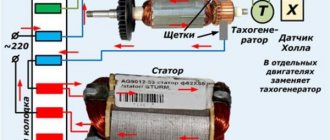
You can repair the stator of an Interskol angle grinder yourself if you know the necessary data. When disassembling a burnt stator, you must count the number of turns of the wire used and its cross-section.
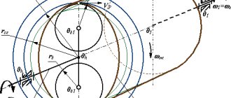
Gear ratio
The gear ratio is calculated using the formula:
where N1 is the shaft rotation speed (rpm) at the input; N2 – shaft rotation speed (rpm) at the output.
The value obtained in the calculations is rounded to the value specified in the technical characteristics of a particular type of gearbox.
Table 2. Range of gear ratios for different types of gearboxes
IMPORTANT! The rotation speed of the electric motor shaft and, accordingly, the input shaft of the gearbox cannot exceed 1500 rpm. The rule applies to all types of gearboxes, except cylindrical coaxial gearboxes with rotation speeds up to 3000 rpm. Manufacturers indicate this technical parameter in the summary characteristics of electric motors.
How to properly remove old grease from an angle grinder
The disassembled grinder gearbox must be thoroughly cleaned of old lubricant. It no longer performs its functions, plus solid particles have already accumulated in it, resulting from wear of moving parts. When mixed with a new one, the old lubricant also significantly worsens its characteristics. Therefore, the gearbox and gears must be thoroughly cleaned.
Removing old grease from the gearbox
Remove old grease with a rag, paper towel or just a rag. Removed parts can also be washed in gasoline or solvent. Before assembly, the washed parts must be thoroughly dried. Residues of solvent or gasoline will mix with the new lubricant and change its consistency, which will again worsen its performance.
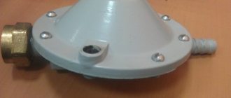
Hydrocapstan
The hydraulic capstan operates not on an electric motor, but on a hydraulic one. In addition to the motor, the unit includes a hydraulic station. Hydraulic capstan differs favorably from a geared motor in that:
- works faster (average immersion speed during installation is 10 minutes);
- allows you to complete a significant amount of work in one shift (up to 40 per day);
- can be used in all weather conditions (summer, winter, dry weather, rain or snow);
- does not require presence in close proximity to the site of the supplied electrical network.
To work with a hydraulic gearbox to install a screw pile, a team of 2–3 people is enough. The barrel diameter is limited to 133 mm. The relatively small dimensions of the product allow it to be actively used in hard-to-reach areas.
Due to the high performance and reliability of such a gear unit, it can be successfully used both on simple objects and for strengthening critical building structures (foundations). The equipment is suitable for construction and reconstruction work.
The simplest regulator circuit
The electrical circuit of the speed controller for the angle grinder is assembled on a printed circuit board or mounted. Moreover, a printed circuit board can also be made independently using PCB and ferric chloride for etching. Instead of iron, you can use a mixture of hydrogen peroxide, salt and citric acid.
Engine speed controller diagram for grinder
Electrical circuit configuration
To make the diagram you will need:
- resistor R1 (4.7 kOhm);
- symmetrical thyristor DIAC (DB3);
- symmetrical thyristor TRIAC (VT-136/138);
- trimming resistor VR1 (500 kOhm);
- capacitor C1 (0.1 µF*400V).
Principle of operation
The operating principle of the circuit is constructed as follows. VR1 is responsible for counting the charging time of C1. When voltage is applied to the circuit, the thyristors are closed, the output is 0. As the capacitor charges, the voltage in it increases and opens the DIAC, which supplies voltage to the TRIAC. It also opens and allows current to pass through. Then both thyristors close and remain in this position until C1 is completely recharged. As a result, a complex wave signal is formed at the output with an amplitude that directly depends on the operating time of the C1-VR1-R1 circuit.
Speed controller connection diagram
Final assembly and testing of the regulator
The circuit is assembled on a printed circuit board or copper (aluminum) radiator
When mounted on an assembly, the location of the thyristors is especially important (strictly on the radiator, it plays the role of a heat sink). Then a mandatory check of the circuit’s functionality is carried out using a regular light bulb.
The smoothness of the change in heat will be the same as in the finished speed controller for an angle grinder after final assembly.
Factory models are equipped with a plastic adjustment wheel; if desired, it can also be purchased separately and included in the homemade regulator kit. If the testing was successful, the regulator is attached to the angle grinder and fits into the power supply circuit of the tool.
Features of screwing screw piles with a “meat grinder”
We will not now dwell on such important issues as those discussed in other articles, such as the selection of piles, calculation of the pile field, site marking, etc.
It is recommended to purchase 1 more pile for test screwing into the same soil as on the site (not far from the future foundation).
It is convenient to do the work of screwing in piles with three people.
- Place the pile next to the installation site;
- Connect the “meat grinder”, including the lever;
- Install the pile vertically according to the markings (pile driver at the top, hold the lever so as not to interfere);
- One holds the lever, the rest hold the pile so that it does not deviate from the vertical;
- Turn on the “meat grinder”, control the vertical position of the pile, continue until the pile is immersed to the desired depth.
Details of screwing piles with a “meat grinder” can be seen in the video:
DIY grease for an angle grinder
A self-made lubricant for grinder gears consists of a base and a diluent. The basis of homemade lubricant is usually a CV joint with molybdenum disulfide or Tsiatim-221. They have a second NLGI viscosity, so for use in an angle grinder gearbox, the base must be diluted. As a diluent, it is best to use simple mineral industrial oil, which, for example, is I-20 oil. To obtain a viscosity of NLGI 0, you will need to mix approximately 70 percent base and 30 percent thinner. The resulting mixture is thoroughly mixed and ready for application to gears and bearings of angle grinders.
Making your own lubricant
Timely maintenance of any electric tool is the key to its long-term and trouble-free operation. A properly functioning tool is also a guarantee of safety for the person using it. Using the tips given above, everyone can choose the right lubricant for the angle grinder gearbox and replace it without resorting to the help of expensive power tool service centers.
Homemade boat motor. Boat motor from a lawn mower.
Re: Homemade boat motor
Vladimir656 » Mar 20, 2022, 8:29 pm
I will continue to upload photos of the creation of the second motor.
Re: Homemade boat motor. Boat motor from a lawn mower.
Vladimir656 » Mar 20, 2022, 8:31 pm
Re: Homemade boat motor. Boat motor from a lawn mower.
Vladimir656 » March 20, 2022, 20:44
Re: Homemade boat motor. Boat motor from a lawn mower.
TATTOOIST » Mar 20, 2022, 09:24 pm
Re: Homemade boat motor. Boat motor from a lawn mower.
Vladimir656 » March 21, 2022, 10:50
Re: Homemade boat motor. Boat motor from a lawn mower.
Dalnoboi » March 21, 2022, 2:24 pm
Re: Homemade boat motor. Boat motor from a lawn mower.
Vladimir656 » Mar 22, 2022, 07:08 pm
How to remove/remove a needle bearing in an angle grinder
Pressing in a new needle bearing is not difficult, but removal requires the use of an original puller. In the following video, the author describes the manufacture of such a device and shows its practical operation.
The puller is an expanding collet with collars at the ends of the movable petals. The dimensions of the collet are made on a lathe, and the central hole is drilled for a rod that spreads the petals. The puller is inserted inside the bearing and the collars, after the rod moves along the hole, rise up and rest against the end of the ring with their side surface. With the help of not very impressive-looking, but reliable levers made of reinforcement with sharpened edges, resting on an inserted washer, the bearing can be removed from the housing.
Important: a needle bearing has a service life significantly longer than a plain bearing. However, during operation, the spindle shaft wears out, which also needs to be replaced. In the described video, the author found a replacement option
However, in most cases this can create additional problems
In the described video, the author found a replacement option. However, in most cases this can create additional problems.
Catalog
| GENERAL CONSTRUCTION TOOLS |
| Angle grinder drills Polishing machines Cordless drills and screwdrivers Hair dryers Grinding machines Hacksaw Electric scissors Measuring equipment Vacuum cleaners |
| CONCRETE PROCESSING AND FINISHING |
| Cordless rotary hammers SDS-plus rotary hammers SDS-max rotary hammers Jackhammers Furrow maker Mixers |
| WOODWORKING |
| Miter saws Routers Circular saws Plunge saw Planers Machine tools |
| GARDEN EQUIPMENT |
| Electric brush cutters, brush cutters Electric lawn mowers Electric chain saws Petrol brush cutters and brush cutters Gasoline lawn mowers Petrol chain saws Washing machines |
| EQUIPMENT |
- CommentAuthor minasrost IP: 91.232.188.221
- CommentTime 02/14/2014
- CommentAuthor Mort IP: 87.228.64.11
- CommentTime 02/14/2014
I didn’t understand the question - how is it - from both sides? The disk is put on the other side and secured with a nut on the flange. How do you want to place the bearing there?
Listen less to all sorts of dreamers.
- CommentAuthor Watson IP: 178.76.222.197
- CommentTime 02/16/2014
- CommentAuthor Mort IP: 37.233.119.2
- CommentTime 02/17/2014
- CommentAuthor minasrost IP: 91.232.188.221
- CommentTime 02/17/2014
- CommentAuthor Mort IP: 37.233.119.2
- CommentTime 02/17/2014 this message was corrected
- CommentAuthor Fenekey IP: 77.40.2.201
- CommentTime 02/18/2014
- CommentAuthor Mort IP: 37.233.119.2
- CommentTime 02/18/2014
Yes, you are right, this is basically true.
I started looking at the diagrams and found a couple of masterpieces.
Installation of saw blades on angle grinders is strictly prohibited by TB
The bearing cannot protect against dust, and the coating does not impair the adhesion of dust, but protects against its abrasive effect.
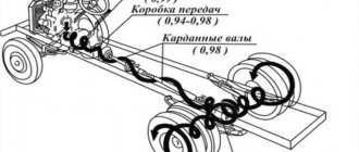
Design, principle of operation and purpose of an angle grinder
The source of torque for grinder tools is a commutator electric motor built into their design. The final working value of the torque on the working attachment is achieved using a gearbox, the design of which is compact to ensure the minimum dimensions of the entire power tool, which is an important parameter for manual use of the device.
Scheme of operation of the grinder. Source here
From the technical name of an angle grinder, its main purpose follows - grinding the surfaces of processed materials. However, the versatility and versatility of grinders allows, with the help of replaceable attachments, to perform such technological operations as cutting, stripping, polishing and some others.
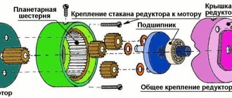
How the gearbox works, sectional view, photos and drawings
The minimum dimensions of the gearbox are ensured by the use of bevel gears. The small bevel gear meshes with the large one, and the direction of rotation of the electric motor rotor shaft changes by 90°, thereby reducing the size of the angle grinder in length. The driven gear, narrow in thickness, allows the design of the gearbox housing to be made as flat as possible, which ensures the operation of the grinder in hard-to-reach places.
Grinder gearbox in section. Photo source here.
The supporting units of the rotor and spindle shafts are made using ball bearings, needle bearings and bushings made of antifriction materials, depending on the model of the angle grinder, capable of withstanding large axial loads. The housing in which the shafts of the driven and driving gears are assembled and the bearing units are reliably protected from dust that is generated when working with an angle grinder. An example of a gearbox design is shown in the image. How to disassemble for the purpose of diagnostics and repairs can be found in a separate article.
Adjustment
The angle grinder's bevel gear will work without problems with shafts rotating freely in bearings that have no backlash.
This is achieved by installing additional metal spacers on the drive and driven shafts to eliminate gaps formed during the assembly process. A special feature of the bevel gear is the adjustment of the gear itself. It is necessary to ensure alignment of the initial cones of the gears. Here you should also take into account the presence of a thermal gap, which prevents the transmission from jamming when heated during operation. To do this, metal gaskets are installed between the housing and the gearbox cover. The correct adjustment is monitored by the contact patch. In practice, this is done by applying a coloring substance, for example, blue, on the surface of the teeth and after running in the operating mode, the area of the working surface of the tooth on which there is no blue is visually determined. The correct location and size of the contact patch is shown in the image below.
Depending on the degree of transmission accuracy there should be:
a = (0.4 – 0.8)b;
hav. = (0.6 – 0.9)h.
In grinders, metal spacers are installed between the cover and the gear housing, the number of which corresponds to the correct initial adjustment of the gearing. As the teeth wear out, to maintain the gap and normal operation of the transmission, some of the gaskets are removed, thereby ensuring the life of the grinder gearbox.
Gear ratio (ratio)
Angle grinder (grinder) MAKITA GA9010C. Photo 220Volt
In the classical sense, the gear ratio of an angle grinder gearbox, like any other mechanical gearbox, is the ratio of the revolutions of the drive shaft to the revolutions of the driven shaft. For most angle grinders it ranges from 2.5 to 4. The gearbox is a reduction gearbox in order to provide speeds at which the surface being processed does not quickly overheat and the torque required for operation is achieved.
To a greater extent, the gear ratio of grinder gearboxes depends not on the manufacturer’s model, but on the power of the grinder. Less powerful angle grinders have higher spindle speeds and, accordingly, a lower gear ratio. For powerful professional angle grinders, high torque is important and high spindle speeds are not used when working with large diameter nozzles to ensure safety. Here the gear ratios are closer to the maximum values.
What types of gearboxes are there: direct, reduction, angular and others?
A mechanical gearbox is a mechanism that transmits from the propulsion system the parameters of torque and shaft rotation speed necessary for the operation of the drive device. Some types of gearboxes can change the direction of their rotation.
Gearboxes with coaxial (parallel) shafts , as a rule, are the most common ones with spur gears. They can have different gear ratios and the number of conversion stages. The power transmission is transmitted smoothly, with virtually no losses, but they cannot change the direction of shaft rotation.
Grinder gearbox with lubrication
Angular gearboxes , which are used in angle grinders, are capable of ensuring the direction of shafts at 90°. Bevel gears can be either straight toothed or circular. Some low-power household angle grinders, for example, Bosch models, use a gear with straight teeth, where there are no requirements for smooth running and noise levels. Circular teeth have a greater load-bearing capacity, have a lower noise level due to smooth engagement, and are less sensitive to assembly errors.
Depending on the gear ratio, gearboxes are divided into the following types.
- Straight. The gear ratio is 1. Such a gearbox is used, for example, in some multi-shaft gearboxes of trucks.
- Promoting. In another way, it is called a multiplier, where the gear ratio has a value less than 1. The main purpose of the multiplier is to increase the angular speed. In this case, the torque on the output shaft decreases.
- Downward. Here the gear ratio is greater than 1. In most cases, in various mechanisms, such as angle grinders, such a gearbox is used.
There is a wide variety of reduction principles, as well as design designs. However, each mechanism is best suited to a certain type. It is already quite difficult to imagine grinders without a bevel gear.
Malfunctions of the angle grinder regulator and do-it-yourself repairs
Some models of angle grinders are equipped with regulators, due to which the rotation speed of the spindles changes. Such regulators are not available on all models, and you need to think about their presence when purchasing an angle grinder. This is a very convenient option that allows you to adjust the spindle speed without changing the power.
This is interesting!
If the tool is not equipped with such an option as adjusting the spindle speed, then you can make it yourself.
To do this, you need to buy a ready-made microcircuit, through which the voltage supplied to the electric motor is changed. The lower the voltage, the lower the rotation speed. The disadvantage of using such a device is that along with the voltage, the power also decreases, therefore, by reducing the speed, the performance of the device also decreases. If you don’t want the engine to burn out at reduced operating speeds and under heavy load (the winding may burn out), you should buy grinders with built-in regulators. In them, reducing the speed does not affect the power, so the tool produces the declared power at any speed. This allows you to avoid overloading the motor and prevent it from accelerating its failure.
This is interesting!
If the motor, or rather the winding, burns out, then the reason for this is excess load.
The windings of grinders for household use especially often suffer from burnout, the owners of which load them to the limit. You can detect a malfunction of the speed controller yourself by the nature of the tool’s operation. If, when moving the adjustment disk, the speed does not increase or decrease, it means that the device has failed. There is no need to rush to buy a new regulator, since first you should inspect the standard one. The malfunction may be caused by broken or oxidized contacts. To eliminate the breakdown, it is enough to solder the wires or clean the oxides on the microcircuit.
If the diagram shows signs of carbon deposits, then the device has failed. You can try to fix it, but only if you have knowledge of electronics. If you don’t have the skills, it’s easier to buy a new regulator of the appropriate design.
When purchasing, you need to pay attention that they differ in design, so choose a similar model for your instrument
We determine the gear ratio manually
Very often, when customers contact our organization, they say that the failed gearbox does not have a nameplate and they have no idea how to find out the gear ratio of the gearbox. This section of the site will be devoted to this issue.
So, calculating the gear ratio of a spur gearbox consists of the following operations;
- we count the number of teeth of each gear and the gear shaft of all gear stages;
- divide the number of gear teeth by the number of teeth of the gear shaft working in tandem with it;
- We perform this operation for each stage - we obtain the gear ratio (ratio) of each stage;
- multiply the resulting numbers by each other - we get the total gear ratio
Calculation of the gear ratio of a worm gearbox consists of the following steps:
- count the number of teeth on the worm wheel
- determine the number of starts of the worm (for example, a regular drill has two starts)
- divide the number of wheel teeth by the number of worm runs and get the gear ratio of the worm gearbox
- if the gearbox is two-stage, we do this for each stage and multiply by each other
As you can see, everything is quite simple. If the gearbox has retained at least some functionality, then it is enough to manually rotate the input shaft of the gearbox to one full revolution of the output shaft. The number of revolutions of the input shaft will be the gear ratio of the gearbox. In a similar way, it is possible to determine the gear ratio of most gearboxes presented in our catalog.
How to repair a gearbox on an angle grinder with your own hands
What a gearbox on an angle grinder is is a pair of helical gears, which are also called a gear or bevel pair. Almost all grinders have gears with oblique teeth, but there are also models with straight teeth, for example, Bosch.
Due to the gears, torque is transmitted from the motor shaft or armature to the spindle - the executive body. The small cone-shaped gear is attached to the shaft, and the large one is connected to the tool spindle. Due to the fact that the second gear has a large number of teeth compared to the small one, the rotation speed decreases. This means that the spindle speed is less than the motor armature speed. However, the lower the speed, the greater the torque, which has a positive effect on the performance of the unit.
Let's return to our gears. They are made of steel, but the quality of this material may vary. Regardless of the quality of the gears, there comes a time when the teeth wear out (especially if the lubricant is not changed) or even break off. If the gear pair is worn out or damaged, they must be replaced, as they cannot be repaired. Moreover, it is necessary to change a pair of gears, and not one at a time. They are also sold in pairs, as they have a distinctive number of teeth. How to replace the gear pair on an angle grinder is described in detail in the video.
https://youtube.com/watch?v=CpwYXu81ACs%3F
Instructions on how to remove the gear pair (gearbox) on an angle grinder:
- First, unscrew the nut from the gearbox side
- Remove the rotor along with the bevel gear attached to the shaft. If the rotor does not disengage from the part of the housing in which the spindle is located, then you need to unscrew the two screws that are located behind the cooling fan
- Knock the gear out of the shaft and install a new one in its seat.
- Remove the second gear from the spindle shaft and install the new gear by pressing it onto the shaft.
Few people know how to repair a gearbox on an angle grinder with their own hands, but if this happens, then you need to arm yourself with the necessary tools and get started. There is nothing difficult in dismantling the gearbox; the main thing is to follow the sequence of actions.
Gear ratio - definition, types of gearboxes, calculation
Worm gearboxes belong to the class of the most common gear mechanisms. Due to their optimal price, they are in demand both for equipping household appliances and for completing heavy industrial equipment (such gears are indispensable in the mechanisms of conveyor systems).
The functions of the worm unit come down to 2 basic points - converting the moment of force (increasing torque) and simultaneous control (adjustment) of the angular speeds of the rotational movement of the engine elements. Pros: price, ability to reduce gears and self-braking. The device operates in the range from 20 to 1 to 300 to 1 or more.
What most often breaks on angle grinders of different brands?
It makes virtually no difference whether your tool is DeWalt or Intertool. Sooner or later there will be a need to start repairing the angle grinder, which can be done easily and quickly if the breakdown is correctly identified. The main reason why angle grinders break down is not the quality of this tool, but the fact that most craftsmen use them incorrectly. How can you use an angle grinder incorrectly?
According to their purpose, there are two types of angle grinders:
- Household - a category of power tools, the main purpose of which is to use them around the house. They are not suitable for constant and prolonged loads, since the parts are made of low-strength materials. You can operate household angle grinders for no more than 10 minutes continuously, after which you need to pause for a similar period of time to allow the engine and other components to cool. Naturally, no one records the time how long he works with the unit. When the need arises, we pick up a tool and carry out the task to the end. The duration of operation of the unit can range from 10 minutes to 1 hour, which results in breakdowns of the angle grinder. Household grinders can last much longer than professional ones, provided they are used correctly. If you need to repair a household grinder yourself, then experts recommend it’s better to immediately buy a new tool
- Professional - a special type of power tool, the main purpose of which is the duration of operation of the device. Their components are made from durable and high-quality materials, so they are durable and resistant to prolonged loads. You can work with professional angle grinders continuously for 40-50 minutes, and not worry about the engine overheating. They are designed for this, so if you are faced with a situation where your household unit often breaks down, then you need to switch to professional models. This is especially true for craftsmen who, in order to save money, buy household models, but at the same time work with them on construction sites, using them for 8-10 hours a day
Knowing the difference between household and professional models makes it easier to choose a power tool. The choice of power tool and its use determines how often you will need to repair grinders yourself.
Let’s look at the question of what most often breaks on grinders. The most common symptoms of malfunctions are:
- The device does not turn on - the next time you need to use an angle grinder, it turns out that it does not work. The causes of such a malfunction may be the following factors: lack of power in the outlet, damaged power cord, loose contacts, broken button or worn out brushes. Often, as practice shows, on angle grinders the place where the power cable enters the housing structure wears out. This is where you need to look for the place where the contact is damaged
- Current flows into the device, but the motor does not work - this means that the button is most likely faulty. The buttons on grinders cannot be repaired, so after a short check, you should simply replace them
- Sparking of the unit during operation and the appearance of a burning smell means that it is time to replace the graphite brushes. They have an appropriate resource, so signs of sparking in the area where the brushes are located means that they are worn out and the quality of contact is low
- The appearance of extraneous sounds after starting the engine - crackling and ringing sounds are signs of wear on the bearings or gears. To find out the exact cause of the instrument's hum, you will need to disassemble it and inspect the mechanical parts.
These are the main types of faults that even a beginner can identify. Bearings and brushes belong to the category of consumable parts, so do not be surprised if after six months of operation of the unit there is a need to replace them. With simple types of breakdowns on angle grinders, everything is clear, but it often happens that everything seems to be checked, but the tool does not work. What to do in such a difficult situation? To do this, you need to delve into the topic of repairing angle grinders and try to understand what is the reason. Often in such cases the “poke method” helps, but we will not rely on it so as not to get hurt. Let's consider all types of defects and breakdowns on grinders, as well as the features of their identification and elimination.
homemade CNC machine, reviews duxe.ru
Share 1 2008-06-26 00:22:55
I would like to present another version of a homemade gearbox. For this I used a helical gear pair from a grinder gearbox, the set costs $4 (I took the cheapest one). The gear ratio is 2.692 (13/35). The gearbox data is already on my homemade machine on all axes and work great. Pros: factory-made gears, high-quality steel, helical gears produce less noise during operation, tapered teeth make fitting and assembly easier, because The cone, being a self-centering and self-sealing (for threads) connection, makes it possible to obtain the most tight, practically free of play, transmission link. Disadvantages - the motor shaft will be located perpendicular to the propeller axis, which may not always be convenient, it is necessary to accurately manufacture the adapter coupling for the drive gear and the fit for the driven gear in order to eliminate possible radial runout and, as a result, the appearance of backlash or jamming during rotation, it is necessary to maintain the alignment of the drive shaft and lead screw when assembling the entire assembly. If all the conditions are met, then to adjust the meshing density it is enough to move the coupling with the gear along the drive shaft, achieving a minimum gap.
Share 2 2008-06-27 23:32:22
That's what I understand. that the need for a gearbox arises when the engine pitch is large? But in general it’s beautiful. Are the steel parts painted or blackened?
- Author: Workaholic
- Blocked
- From: Tundra
- Registered: 2007-11-03
- Invitations: 0
- Posts: 1348
- Respect: [+60/-1]
- Positive: [+9/-1]
- Gender: Male
- Age: 59 [1958-01-19]
- Spent on the forum: 1 day 10 hours
I understand that this is 3rd grade math, but I don’t get a WHOLE number of steps per mm. Or he's completely dumbed down. I also bought two sets of gears, also around $4. I want to use screws from Zhiguli jacks, and their pitch is 4mm. With a gearbox it would be just fine, but these are fractional steps. How did you solve this issue?
No problem. VRI-CNC allows you to enter a fractional step value, personally tested with an accuracy of up to the 4th decimal place.
Assembling the tool with new parts
After disassembling the instrument and necessary replacement of all damaged parts, we will reassemble it. Make sure you have all the tools, lubricants, and clean rags on hand for finishing touches.
All previous grease must be removed and replaced with fresh grease. Use lubricants from trusted manufacturers, buy them in specialized stores.
First of all, you need to assemble the rotor. You need to press in the bearings and install the impeller. Before doing this, carefully lubricate the bearings. Using a wooden tool, press them onto the top of the shaft.
Cover the collector bearing with rubber protection. This is the same diagram of how to assemble a rotor shaft.
Next, we reassemble the gearbox. We begin this process by installing the gearbox on the rotor shaft housing. When the shaft is already inside the housing, place the drive gear on it, then the washer and fixing nut.
Now install the gear housing, together with the shaft located in it, inside the stator housing. It is necessary to press both housings after the commutator bearing is already in the seat. Next, check whether the rotor rotates easily on the bearings.
The final step is to place the lid back where it was. Check how the spindle shaft rotates. If you determine that the rotation is easy even with the movement of your hands, you can start tightening the screws. They secure the cover to the body. Before doing this, lubricate all screws using sealant.
Operational coefficient (service factor)
Service factor (Sf) is calculated experimentally. The type of load, daily operating duration, and the number of starts/stops per hour of operation of the gearmotor are taken into account. The operating coefficient can be determined using the data in Table 3.
Table 3. Parameters for calculating the service factor
| Load type | Number of starts/stops, hour | Average duration of operation, days |
| The ability to use the same power tool to process various materials (metals, stone, wood, plastic, concrete and others) makes the grinder very popular among users. The dimensions of the nozzles together with the gearbox provide optimal speed for safe and efficient work. |
Recommendations from foreign manufacturers
Meanwhile, manufacturers of imported angle grinders recommend using only their specialized lubricant. This is justified by the fact that the uniquely developed composition significantly extends the service life of the mechanisms and therefore the warranty service is extended for a longer period.
Bosch branded lubricant
And if the conditions are not met, they refuse free service in case of breakdowns. Reasoning that they arose due to the use of low-quality and cheap lubricant. And in order to justify the high cost of their consumables, they add expensive and rare components to the composition.
Explanation of the markings that the branded lubricant for angle grinders has:
- If molybdenum is introduced as an additive, then the marking is MOS2.
- When the viscosity grade is increased to the second, NLGI2 is indicated.
- To confirm the ISO standard, set ISOL-XBCHB 2.
- German quality is indicated by the DIN marking.
- For a special standard from Germany for type “K” the numbers 51825 are prescribed.
Literally all famous brands use such techniques. From Makita and Bosch to Hitachi and Interskol.
For bearings
When manufacturing an angle grinder, bearings already filled with a lubricant are installed in it. But intense heating during operation transforms the mixture into a liquid state, and it flows out. Therefore, during scheduled maintenance, the bearings must be filled each time.
It is necessary to select the composition so that it meets the requirements:
- increased sliding;
- reduced friction;
- performed cooling;
- prevented corrosion;
- protected from dust;
In addition, it is necessary that the properties of the lubricant remain unchanged at temperatures up to 150°C. And lithium compounds have proven themselves better than others for parts in gearboxes. Mixtures CIATIM-203 and VNIINP-242 are also good.
Heat Resistant Bearing Grease
But the bearing, which is installed to help the electric motor, has a different temperature regime. The rotation speed and load also differ. Therefore, when choosing a lubricant, not only general protective factors are taken into account, but also these indicators. And here you will need pigment lubricants VNIINP-246 and VNIINP-235.
For gearbox
Lubrication of the angle grinder gearbox occurs in a completely different way. The whole process comes down to spraying the mixture and suspensions. It seems that the gearbox operates in a fog of oil droplets. Therefore, there are special complaints about lubrication. And the most important thing is the increased adhesion of the composition.
And in addition to tight adhesion, the mixture in the reducer must be heat-resistant and not spread at elevated temperatures. As a rule, both Western samples, which have a high cost, and our domestic special lubricants for power tools have all the necessary properties.
Multi-purpose lubricant
Circumstances often arise when the necessary factory products are not at hand. And in this case, it is often not money that is important, but time. When it is not possible to visit a specialized retail outlet and work needs to be done, a homemade composition will help.
Automotive CV joint
The basis should be a mixture with high adhesive properties. And for these purposes, lubricant for the joint (CV joint) in a front-wheel drive car is perfect. This unit has to operate under increased shock loads in a polluted environment. Among constantly changing temperatures and humidity.
Since the lubricant for CV joints is very thick, it must be diluted to the desired consistency. It is best to use MS-20 oil for this purpose. It is introduced practically drop by drop and constantly stirring thoroughly with a mixer.
You can also use a combination of two lubricants. Take CIATIM-221 as a basis and introduce a little TAD-17 into it.
How to compare the age of a cat and a person
Cat owners often try to correlate the age of their pets with the human age, using a popular method - multiplying the cat's age by seven. Thus, a one-year-old animal is a seven-year-old child, a two-year-old cat is a fourteen-year-old teenager, a three-year-old is a twenty-eight-year-old young man. In fact, this ratio cannot be called correct, because, for example, at seven years old a person cannot yet have offspring, while a one-year-old cat is quite capable of reproducing.
Feline scientists offer other methods of counting, which vary depending on the age of the animal. Thus, a one-month-old kitten is developmentally equal to a six-month-old child, and a two-month-old kitten is equal to a one-year-old child. At the age of one year, the physical and mental development of a cat is the same as that of a person at 15 years old. This ratio seems quite reasonable: during the first year of life, the cat learns to live independently: get food, take care of itself, defend itself, and get along with others. A person does approximately the same in the period from birth to 15 years.
The period from two to eight years is the age of full bloom for a cat. It corresponds to 24-48 years in humans. This is a time of greatest physical activity and increased interest in the world around us. After reaching 8 years of age, the cat enters middle age. As with people, this period can progress differently in animals: some cats are healthy and full of energy, while others are beginning to experience the effects of approaching old age.
How to remove a needle bearing or a damaged journal bearing race
Grinder gearboxes use various bearings. They are subjected to heavy loads and do not cause malfunctions.
Bearing failure is determined by an increase in spindle shaft play. Having disassembled the gearbox housing without dismantling the large gear shaft, the needle bearing is visible.
The needle bearing is not used in many angle grinders. In the same grinders in which it is installed, its dismantling is carried out in several ways.
Having removed the destroyed part of the bearing, there is an option to remove the inner race using a machine tap. Clamp a machine tap of a suitable diameter into the screwdriver chuck and do not try to screw it into the bearing race until the tap rests on the bottom of the housing. Continue to slowly screw the tap into the cage. It will lift the clip along the threads.
The second method is that the remaining race of the destroyed needle bearing can be removed using a special bolt not a retaining ring.
General definition
The gearbox, as a structural element, is used in many mechanisms. This is a technical unit necessary to correct the rotation speed when transmitting motion. The invention and spread of gearboxes occurred during the development of engines of various types. This is explained by the fact that there is a need to convert high rotational speed into torque force, or vice versa. For various purposes, there are many types of gearboxes, the choice of which plays a vital role for the normal functioning of the mechanisms.
The gear ratio is the main parameter that characterizes various gearbox models. It depends on the type, parameters and gear stages.
The gear ratio of the gearbox is indicated by a multiplier, which indicates the type of mechanism: it is reducing or reducing. Reduction gearboxes have a multiplier greater than 1; a gearbox with a gear ratio less than 1 is called an overdrive gearbox.
In cars, gearboxes are used to redirect the power impulse to the wheels from the gearbox, and the rotation speed is always reduced. The gear ratio is an indicator of how many times the speed will decrease. If the gear ratio is 4, this means that the torque transmitted from the gearbox to the axle is 4 times less than the rotation speed of the transmission.
Typically, such a mechanism is installed on the drive axle; if the car is all-wheel drive, then two are installed, one on each axle.
The gearbox does not have to strictly comply with the established factory parameters; in some cases, if it breaks down, it can be replaced with a new unit with a lower or higher gear ratio. How to check which mechanism is suitable? Usually you can replace it with models in which the nominal gear ratio differs by no more than 0.5 up or down. If we take, for example, gearboxes of VAZ cars, it is possible to install 4 models. Accordingly, the speed of the gearbox decreases as the gear ratio increases.
Therefore, the speed of the car directly depends on the speed of the gearbox, and by replacing this unit you can make your car faster, for example, by installing a unit with a gear ratio of 20.
If the car is used for cargo transportation or driving over rough terrain, it is recommended to install a model with a lower gear ratio. This will add power to the axle despite the reduction in speed.
When replacing a unit with a model with a higher or lower number, you should take care of the correct operation of the speedometer. Since very often it begins to show incorrect indicators. You need to either replace the cable in case of a serious failure, or simply adjust the speedometer.
Surprisingly, when replacing a gearbox, removing the old one and installing a new one is the easiest thing; the most difficult thing is to correctly adjust and configure everything so that the total gear ratio corresponds to the necessary parameters. If this fails, then even the highest quality gearbox can quickly fail.
Determination methods
There are several ways to determine the gear ratio:
The first, simplest, method is theoretical. Usually, in order to find out the necessary information, you just need to look at the car’s instructions, where detailed tables are indicated. Most cars contain such information in the Vin number, where it is encrypted, but it is easy to find out. Russian-made cars usually have a standard set of standard gearbox models. This greatly simplifies the replacement process.
It's a different matter when it is necessary to replace only a separate part of the assembly. Usually, when a car has had several owners, it is not known how many times the gearbox has been replaced and what model is currently installed. This is often quite easy to do, since they try to put the necessary information in places that are most convenient for viewing.
The practical method of determining the gear ratio is more complex and requires direct intervention in the vehicle mechanism. Let's look at the detailed step-by-step instructions:
- The first thing you need to do is find out what model is installed on your car. There are several types that differ depending on the type of gear transmission, there are gear, chain, screw, hypoid, wave and fractional. In any case, the gear ratio is calculated as the ratio of the rotation speed of the driven and drive shafts. If the above data is known, you will have to resort to disassembling the node.
- It is necessary to disconnect the gearbox from the housing and related components and open the cover to have an overview of the structural elements. With the help of such manipulations, you can find out exactly which element of the gearbox you should start from when calculating.
- Then calculate the gear ratio based on the type of unit. If the transmission is geared, then the calculation is quite easy; in this case, the calculated indicator is equal to the ratio of the number of teeth of the driven gear to the teeth of the drive gear. You just need to calculate the specified parameters.
- If the transmission is belt driven, the calculation is made by the ratio of the diameter of the drive pulley to the driven one, or vice versa. The calculation is always carried out from the larger number. With a chain drive, you need to count the number of teeth of the drive and driven sprocket, and calculate the ratio of the larger to the smaller. With a worm gear, the number of runs on the worm and the teeth on the worm wheel are counted, after which the ratio of the second number obtained to the first is calculated.