Features of the design and purpose of the machines
The following main components are present in products of any group:
- Electrical part.
Consists of an electric motor with drive. Its power varies and is determined individually for each model. Equipped with additional parts to control performance. Compliance with safety requirements is mandatory for this piece of equipment.
- Transmission.
Helps transfer driving force from the shaft or lead screw to the caliper.
- Caliper.
Secures the cutting element. A support is also needed to feed the tool across or along. And so that this procedure is carried out in compliance with certain parameters. The caliper has carriages located at the bottom. There is only one, but some models come with several. The carriage at the top is where the lathe tool holder is attached.
- Spindle head.
The spindle is located here. The gearbox is located inside the device.
- Apron.
Converts movement, the source of which is a roller or a lead screw.
- Bed.
An element with a load-bearing function on lathes. The remaining parts are attached here.
The parts included in the kit rest on two stands. These cabinets become the load-bearing element. Thanks to this, the operator can set the position of the structure that will be most convenient. The cabinets are distinguished by their massive construction. A separate question is what the products are intended for.
The main purpose of this type of equipment is the processing of metal parts of various characteristics and shapes.
https://youtube.com/watch?v=Xq1H0f2A37s
How to choose a metal lathe (video)
Buying a lathe is, without exaggeration, the purchase of the century for many guys, especially if it is purchased for the first time, that is, it will be the very first machine. In this video from Igor Negoda’s channel (YouTube) we are talking about choosing and checking a TV-4 lathe, because most people want to buy just such a machine for working on metal. All these techniques are also applicable to other machines, larger ones, but usually large ones are bought by people who understand this matter, so this information will not be so useful to them.
Excellent choice for a turner in this Chinese store.
The video on how to choose a good lathe will consist of 2 parts. The first part is a check without any tool, which is what you need to pay attention to first, but in the second half, the check will be done using an indicator. The first thing you should pay attention to is the completeness of the machine. Believe me, this is an important point, because if you don’t have enough tailstock, you will have to pay a tidy sum for this task, or try for a long time to make it yourself. The tailstock is not a simple thing, on TV-4 they are expensive, due to the fact that they are constantly lost, I don’t know why. And plus, if you don’t have a tailstock and buy yourself another one, it will not fit this machine - this is 100%, because each tailstock is an individual part of the machine. But, the old tailstock, that is, if the machine is worn out, it will still not be centered, its center will be lower than the center of the spindle. This matter will need to be corrected, as for example with the author of the video, who corrected it using the simplest method, when he didn’t even know how to scrape, knew nothing about this matter, was just beginning to comprehend, he simply made overlays on the sole and raised the tailstock, that is I got out of it in such a simple way and the whole thing still works in this state. Next, a guitar must be present on the metal machine. This is a set of gears that drive the feedbox. You will not be able to turn on the automatic feed; it is turned on by a lever. Finding these gears is also very difficult and they will not be cheap. According to the latest data, about 2000 for the gears and the cheapest I’ve seen is 4500 for the tailstock, that is, have some idea if this is not enough for you. Further, it is desirable that there be a cartridge, if there is no cartridge, you will also have to pay a very round sum for it, which will add to the price of the machine, although finding a cartridge is not a problem - this, let’s say, is the least of evils, but it is desirable that the cartridge be all- it was, because new cartridges cost about 5000, 125th. If a seller with a machine gives you all kinds of junk, ask him if he has additional cams in stock, because cams are also very rare and quite difficult to find. The author has only bought one set of reverse cams so far. Continued from 4 minutes
DIY lathes
There are many options on how you can make a mini-lathe with your own hands, depending on the tasks being performed. True, homemade installations are still more often used for side processing of wooden parts than metal ones.
You can make a lathe from an electric motor with a power of about 1 kW with a reduced speed.
A faceplate is installed on the engine axis, onto the cones of which a wooden blank is placed and securely fastened. The second end of the workpiece, as expected, must be secured in the center. The center is a metal rod threaded along its entire length, secured in a sleeve, which, in turn, is pressed into the central hole of the ball bearing. The bearing is inserted with interference into a cage welded to a metal corner holder.
The rod and the central cone of the faceplate must be aligned, this must be carefully monitored when installing the machine. When operating such a device, the cutter must be held with your hands, resting it against special bars so as not to jump off, which is why a low-speed engine is needed.
You can make a lathe using a drill, upgrading it for metal processing. In this case, the processing tool must be held in the hand or attached to the base at a certain angle.
Universal machine control
The main element of the unit is the synchronizer, which electrically connects the correction mechanism with the control stops. The control stops are designed to allow the hydrocopying and mechanical supports to operate in an automatic cycle with the cutter passing through the center of the product and changing the direction of the product.
Equipment, characteristics
You can find out the price, additional information about the Lathe Lathe 1M692 and its analogues, their characteristics, prices, or open an order by calling us by phone in Moscow, or by phone in the city of Yaroslavl. You can also send us your request by e-mail to We will be happy to help you with the selection of the necessary equipment!
Lathe
A head lathe is one of the types of lathes. Their specificity is turning of large-diameter parts with short lengths. This turning equipment also makes it possible to process massive flat cylindrical workpieces or process short parts such as rotating bodies with significant fluctuations (differences) in diameter in any part. Most often, with the help of lathes, the end part of a workpiece fixed in a faceplate or its edge is processed, threads are cut on the surface of the part, or operations are performed to grind its end surface.
Lobe lathes have no tailstock, the machine bed is low and short, and the centers are located high. To work with large diameters (more than 200 mm), the headstock is located separately from the support (in this version, both the support and the machine spindle are equipped with an individual drive).
The front lathe has several differences that allow it to be clearly distinguished from other machines in the turning group:
- fastening of large diameter parts on the spindle (faceplate);
- lack of tailstock;
- low spindle speed;
- separate drive of spindle and support;
- possibility of carrying out grinding work;
- the possibility of securing workpieces in centers is eliminated.
Using a lathe, turning of cylindrical, conical, shaped, and face-type surfaces of various pipes, disks and shafts is carried out. This machine is ideal for the production of cast iron and steel flanges, rings or disks (less commonly, flywheels, pulleys and gears). The horizontal axis of rotation of the part and the large amount of free space make it possible to process massive multi-ton parts of short length on the machine.
The front lathe is mounted on a concrete base. A frame and a cabinet are attached to the stove. The latter houses the headstock with drive and gearbox. The headstock is equipped with a spindle with a specially designed chuck, which allows for fastening large-diameter workpieces.
On the frame there is a support with devices for clamping and holding the cutters and an apron equipped with a carriage. When replacing the tool holder with a grinding head, turning the metal with a cutter can be replaced by grinding work.
The caliper has a smooth feed provided by the operation of a separate motor.
The electric motor driving the main drive is located separately and is also mounted on a massive base. This equipment layout option can significantly reduce the impact of vibration distortions on the part processing process, which simplifies the process of fine grinding of the end surface of the part. In some cases, by special order, lathes are equipped with tailstocks. This solution allows you to significantly expand the technological capabilities of the equipment.
Equipping the caliper with an eight-position head significantly increases the range of production operations and increases the speed of switching between them. Installing a conveyor for removing chips greatly simplifies the work when incorporating machines of this type into small-scale production. Turning of parts is greatly accelerated by installing contour-type numerical program control devices on the lathe. This innovation allows you to automatically move the cutter along a given curved path and change the spindle speed to maintain a constant cutting speed.
Carousel machines
Vertical turning machines (Fig. 2) are designed for processing massive parts of large dimensions. The main feature that distinguishes these machines is the vertical location of the spindle axis and the large diameter of the faceplate.
Figure 2. Design of a rotary lathe.
Figure 2. Design of a rotary lathe.
Vertical lathes consist of the following elements:
- Table with a rotating faceplate. The table serves as a support for the workpiece. The workpiece is secured in the faceplate. The faceplate rotation mechanism is connected to the feed box via a shaft.
- Faceplate protective guard. Serves to protect the machine operator from rotating parts during operation.
- Vertical support. Designed to feed cutting tools into the working area.
- Pendant control panel. It is used to control the operation of the machine.
- Adjustable hanging mechanism of the control panel. Allows the operator to stand on the side of the machine where it is more convenient to control the processing process.
- Crossbar. Serves to secure the support with the ability to move it horizontally and vertically.
- Drive mechanism for moving the cross member. Consists of an electric motor, two bevel gears and a screw gear.
- Bed. All components of the machine are fixed to the bed.
- Mechanism for controlling the movement of a vertical support.
- Vertical support feed box. Designed to change the feed speed of the vertical support, as well as to configure automatic feed.
- Gearbox. Serves to change the speed of the working movement.
- Casing. Protects the final drive.
- Feed control mechanism.
- Lubricant supply device.
- Horizontal support. Designed to move a cutter located horizontally. Not all rotary machines are equipped with such a device.
- Feed box for horizontal caliper.
Vertical lathes are capable of processing workpieces whose size and weight leave no other choice of metal-cutting equipment.
General Features
The operating principle of lathes is to rotate the spindle with the workpiece. Feeds in the longitudinal and transverse directions are made by moving the caliper with the cutters fixed in it, or the tailstock when processing with an end tool.
These devices are used for turning various surfaces, creating grooves and holes of various shapes, cutting off, rolling corrugated surfaces, drilling, countersinking and boring, reaming, cutting threads in different ways for shafts, bushings, and disks.
Lathes are classified into semi- and automatic, vertical and horizontal, according to the location of the supporting device for fixing the workpiece and spindle. Vertical models, which include frontal lathes, are used for heavy short objects of large diameter.
Differences
The following features distinguish the lathe from other models:
- lack of tailstock;
- high location of centers;
- short and low bed;
- axis of rotation in the horizontal plane;
- placement of large diameter objects on the spindle;
- impossibility of placing them in centers;
- large diameter faceplate (up to 4 m);
- low spindle speed;
- possibility of grinding;
- the support and spindle are driven separately.
As an example, a lobe lathe model 1A693 is considered below. The drive power is 30 kW, the rotation speed is 0.8 - 6.3 min -1, the weight is 58 tons. The machine can process objects with a diameter of 3.2 m (this is the distance between centers) weighing up to 16 tons.
Lathe
Lobe lathes are a type of lathe. They have one remarkable feature: they are adapted for processing parts whose shape is a body of rotation of a large diameter (cylinder, cone, shaped surface). Simply put, these machines can be used to turn cylindrical workpieces of large diameter and small thickness (for example, pulleys, wheels, semi-finished gears, sprockets, flanges and other parts of this kind). You can easily process both the ends of the blanks and the edge part of their circumference. You can also machine grooves, bore internal surfaces, and cut threads on cylindrical surfaces of parts. End grinding machines are widely used for grinding end surfaces.
In them, the axis of rotation of the workpiece is always horizontal. Lathe
- This is a specialized lathe. It has design features that differentiate it from a conventional lathe. Its layout is as follows: a base with a plate on which the headstock with a faceplate is located; there is also a support with a base, and the tailstock is mounted on a high stand. The gearbox is located in the headstock, which is rigidly fixed to the plate. But the base of the caliper along with the longitudinal guides, as well as the tailstock, can be moved along the plate in different directions and bolted to it in the required positions. The bolt heads are recessed into the grooves of the plate and cannot be turned.
The workpiece being processed is secured to the faceplate using bolts and clamps or directly in the cams. If necessary, the workpiece can be supported by a center mounted in the tailstock. And now the main nuance: there is a special recess in the slab, which is located directly opposite the faceplate. This is what makes it possible to process workpieces whose diameter exceeds the diameter of the faceplate. The rotation of the spindle and the transverse and longitudinal movement of the caliper are driven by a special electric motor. It is this that, together with the gearbox, provides a wide range of speeds and feeds of the spindle and support.
In industrial factory production, lobe lathes turned out to be almost completely replaced by rotary machines. But they are still in demand in the individual production of large-sized parts and when carrying out repair work in workshops.
3.3.4. Frontal lathes
To process short workpieces of large diameter and short length, such as pulleys, large gears, flywheels, in individual production conditions, as well as in repair shops, face-to-face lathes are used.
In appearance, they differ from lathes in their relatively short length and large (up to four m) faceplate diameter, as well as the absence of a tailstock.
Figure 20 shows frontal machines with a support mounted on the same frame with a spindle head and with a separate support.
The machines consist of the following main components: a headstock with a gearbox and main electric motor, a faceplate, and a caliper. A machine with a common bed has a feed box that transmits movement to the running shaft.
Machines with a separate support are designed for processing particularly large parts exceeding the diameter of the faceplate.
To do this, a recess is made in the foundation under the faceplate. The feed drive of the support of such a machine is carried out either from a separate electric motor or through ratcheting devices.
| A) | b) |
Fig.20. Front lathes:
1 – front headstock; 2 – electric motor of the main movement drive; 3 – faceplate;
4 – caliper; 5 – feed box; 6 – running shaft
Currently, due to low accuracy, difficulty in installing the workpiece, as well as low productivity, frontal machines are rarely used; they were replaced by more advanced rotary lathes.
3.3.5. Rotary lathes
Rotary machines are used for processing heavy parts of large diameter and relatively short length; They can be used to perform almost all types of turning work. The horizontal arrangement of the plane of the round table (faceplate) on which the workpiece is mounted greatly facilitates its installation and alignment, which is very difficult when processing large heavy workpieces on lathes and lathes.
Rotary machines are produced single-column with a faceplate with a diameter of up to 1.6 m and double-column with larger faceplates for processing parts with a diameter of up to 16 m or more; There are rotary turning machines that can process parts with a diameter of up to 24 m.
Rotary lathes belong to the fifth type of lathe group (for example, 1B502, 1508, 1512). A characteristic external feature of such machines is a table (faceplate, carousel) rotating about a vertical axis with a workpiece. They are used in conditions of single and serial production when processing large-sized cast or welded workpieces. Sometimes, with very large masses and sizes of workpieces, when it is impractical or impossible to carry out processing using machines of other groups, the technological capabilities of rotary machines are expanded by installing special devices on them - heads for grinding, milling, chiselling, drilling, etc.
The main components of the machine are shown in Fig. 21. The supporting system of a two-post rotary lathe consists of a table base 1, two posts 12 and a cross member 7, forming a portal. On the base there are annular guides for rotating the table 2 with the required cutting speed for a given diameter of the workpiece 3. A traverse 6 moves along the guides of the racks to install two supports at the required height: a revolving one with a turret head 9 and a vertical one 4 with a tool holder. The turret support allows cutting tools to be mounted on each of the five faces of the turret. The head can rotate 1/5 of a circle relative to the horizontal axis, the caliper can move horizontally along the traverse using screw 8 and vertically or obliquely along its own guides. The vertical support also moves horizontally along the traverse and vertically or obliquely along its own guides. In addition to those mentioned, there is also a side support 11, which moves horizontally along the rack at feed speeds Sв and Sг. The machine is driven by an electric motor. The rotation speed of the carousel is changed in steps from the gearbox. All calipers are fed from the feed box. The presence of three (and sometimes more) supports allows for parallel processing of the end and outer surfaces and holes of the workpiece. The control of the machine is concentrated on two pendant consoles - left 5 and right 10, duplicating the main commands.
Fig.21. Vertical lathe
On rotary machines with a small-diameter faceplate, workpieces can be secured using self-centering devices. As the size of the workpieces increases, separate cams, strips, jacks, stands, cubes, etc. are used to align them and secure them on the faceplate. Transportation of workpieces to and from the faceplate is carried out in the latter case by cranes or special lifts with electromechanical or hydromechanical drives.
The workpiece is checked on the table, i.e. give it the correct position relative to the axis of rotation and the table surface. Alignment is carried out using an indicator mounted motionless relative to a slowly rotating workpiece, using the structural elements present on it such as a central hole, outer diameter, recess diameter, etc. In some cases, reconciliation is carried out according to the markings, i.e. special marks and points on the workpiece that define the boundaries or position of the machined surface.
Fastening of workpieces must be quick and reliable, which is achieved by a mechanized hydraulic, pneumatic or electromechanical device. The aligned and secured workpiece is subject to rotational movement along with the table. This motion is a cutting motion with a given cutting speed. The feed movement is carried out by cutting tools installed in the tool holders and in the turret head of the calipers.
The combination of feed movements with rotation of the workpiece allows the processing of external and internal end, cylindrical and conical surfaces. An example of processing one side of a pulley is shown in Fig. 22. In the turret head, four of the five positions are occupied by tools: I – drill, II – two cutters in a special holder, III – scoring cutter and IV – boring bar with cutter. Six transitions are performed in one installation, and in the second and fourth transitions parallel processing is carried out with tools from two supports. In addition, in the second transition from the turret head, parallel grinding of two end surfaces is carried out: the hub and the pulley disk. In addition to the elementary surfaces shown in the figure, complex profile surfaces are processed, for which special copying devices are used.
Fig.22. An example of processing a pulley on a rotary lathe
studfiles.net
Types and varieties of turning equipment
There is a division of machines according to the following criteria:
- The largest permissible size of the workpiece being processed above the bed.
- RMC – distance between centers (small – up to 150 mm, medium – 150–300 mm, large – more than 300 mm).
There are also many types of lathes, each with its own specific characteristics:
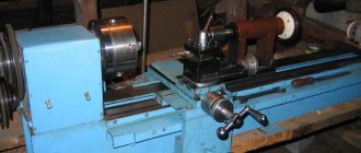
Screw-cutting lathes
Lathes are very common due to their versatility. The principle of operation is simple: an object clamped on a spindle in a horizontal position is given rotation, and cutting occurs with the help of a movable cutter. The cutter can be either fixed or separate.
Turret machines
As the name suggests, a support with a turret is located on the bed guides. A cutter can be installed in each groove of the turret head.
During processing, the cutters replace each other, scrolling, which eliminates the need to waste time replacing tools.
Carousel machines
Designed mainly for processing large objects weighing several tons. The main structural element is the faceplate - a horizontal disk on which the workpiece is mounted and which gives it rotation.
Hence the name of this type of machine. As a rule, a rotary-type machine has two supports for installing cutters - vertical and lateral. This allows you to process the workpiece on the outer and inner surfaces.
Backing machines
Backing is a special method of sharpening the end surfaces of tools for drilling, milling and threading.
This operation is necessary to restore the shape of the working surfaces of the tool after long-term use. The design of the backing machine is similar to a screw-cutting machine, but has a number of features.
The object being processed is also rotated by the spindle, and the support, together with the cutter, performs reciprocating movements, cutting off (backing) the surface of the object by one tooth.
Lathes
They are similar to rotary lathes and also have a faceplate, but on lobe lathes the faceplate is installed vertically. Rotary and lobe lathes can mutually replace each other.
As a rule, they are used for cutting from the end, that is, from the “forehead”. Hence the name. Designed for processing objects whose diameter significantly exceeds their length (wheels, gears, pulleys).
Machines with continuously variable drive
A continuously variable drive is a mechanism that allows you to smoothly change the spindle rotation speed, without sudden changes and stopping the machine.
This function allows you to gradually select the desired rotation speed during operation, rather than estimating it “by eye”.
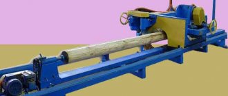
Pipe cutting units
As the name suggests, they are designed for processing pipes. They are very similar to screw cutting machines, but there is one significant difference in the design of the spindle: in order for long pipes to be securely held, a tunnel passes through the body of the machine, in which the pipe is clamped by the spindle at two points.
This ensures that the object rotates without play. There are also additional supports for pipes if they significantly exceed the distance between the cartridges.
Turning and milling machining center
A multi-purpose complex that combines turning and milling functions. It has a milling head on which a cutting tool can be mounted.
This head is movable and can process an object both from the side, on the outer surface, and from the end, on the inside.
Automatic longitudinal turning
Designed for serial production and processing of small-sized parts with a diameter of 1–60 mm and a length of 5–300 mm.
The machine is designed as follows: a workpiece is secured in a movable spindle using a collet, while the cutters remain stationary or move horizontally; the spindle together with the workpiece is brought one by one to the required cutters and processed.
Multi-spindle lathes
Machine tools with three or more spindles on which workpieces are mounted for simultaneous or alternate processing. Used exclusively in mass production.
What accuracy classes exist and how do they differ?
The accuracy class is a generalized characteristic of measuring instruments, which is determined by the limit of errors (main and additional), as well as a number of properties that influence the accuracy of measurements made with their help.
The error limit is the greatest error of the measuring device at which it is suitable for measurement. The limit of permissible basic error is expressed in the form:
- absolute;
- relative;
- given
Errors. The class characterizes the property of accuracy of measurements using this device. And the accuracy of measuring instruments is the quality of a measuring device, which indicates that the error of the measurements is close to zero.
If we are talking about the class of accuracy that is provided, for example, by a lathe, then here we mean the class of surface finish of the part that this equipment is capable of providing during the processing of the workpiece.
Measuring instruments, as well as processing equipment, have the following accuracy classes: 0.01; 0.015; 0.02; 0.025; 0.04; 0.05; 0.1; 0.15; 0.2; 0.25; 0.4; 0.5; 0.6; 1.0; 1.5; 2.0; 2.5; 4.0; 5.0; 6.0. In addition, there are several categories of accuracy classes:
Special
This “Class C” is the highest class of equipment accuracy (both measuring and processing). This class includes machines (in our case, lathes) that must process workpieces to obtain the highest class of surface finish (0.01-0.015).
High
For example, jewelry, medical and laboratory scales have a high level of accuracy. Another name for such equipment is precision. It is marked “class B”. If we are talking about turning equipment, then a high class of cleanliness (0.02-0.025) is provided by polishing lathes.
Normal
The normal accuracy class (the marking is “class H”, but as a rule it is not placed) means such a characteristic of equipment or a part that ensures identical results in no less than 98% of obviously identical objects. The absolute indicator of the normal cleanliness class is in the range (2.0-0.6).
Particularly high
Equipment of a particularly high accuracy class is marked for this indicator as “class A”
When designing high-precision equipment, increased attention is paid to the quality of spindle bearings
Here, rolling bearings are mainly used, also of high accuracy classes, and sliding bearings are made in the form of adjustable tapered bushings. (All standards here are established by GOST 1969-43).
Increased
This accuracy class is marked “class P”. The use of elements of a higher accuracy class (primarily bearings) increases the cost of the finished product processed on such turning equipment.
However, if it is necessary to obtain a higher class of workpiece processing, then elements of a higher accuracy class are used for positioning machine shafts, where higher accuracy and rotation speed are required.
Overview of species
All turning and milling units have their own code in the form of numbers and letters. Using it you can find out the capabilities and create a description of this or that equipment. Typically, such a code contains three or four characters: the first number is the group to which the mill belongs, the second is the type of apparatus, the third and fourth are a description of one of the main parameters of the mill or material to be worked with. If there is a letter after the first designation, then it indicates how much the base model has been improved or not. The letter after the entire digital part indicates the accuracy class, features and modification option of the base model.
Back in the USSR, a certain classification of machines for working with metal workpieces was created, where all equipment was divided into nine groups, each of which is divided into several subgroups.
The design of milling equipment is quite diverse, but in general it can be divided into two main types:
- general purpose or universal mills - this includes vertical, horizontal and longitudinal milling;
- Specialized mills are key-type, rotary-, slot-milling, milling with a copier and others.
Lathe-screw-cutting
This type of lathe is considered universal, which is why it is used in the production of single parts and parts produced in series. With its help, you can create screw threads of modular, metric and inch types, as well as process metal parts.
Lathe-rotary
Carousel-type equipment is usually used for processing large workpieces. Are used:
- for working with workpieces in the form of cylinders and cones;
- for creating grooves of different configurations;
- for milling, grinding and trimming end parts;
- to create screw threads.
The configuration of this machine includes a special table with a faceplate, stands and supports.
Lobototurn
Lobo-turning equipment processes parts of cylindrical and conical shapes, and frontal blanks. The main difference is that the axis of rotation is located in the horizontal plane.
Turning and turret
The turret group of mills is used to work with parts made of calibrated rod. The equipment received this name due to the way the tools are attached to it: they are fixed in a static or driven holder. This feature gives the equipment many capabilities: boring, turning and shaped turning, drilling, threading, reaming, milling.
Turning and milling machining center
For turning, metal-cutting cutters are used, fixed in the milling head. This increases the number of machine functions.
Automatic longitudinal turning
Used in the mass production of small-sized parts from rods, profiles and wires made of alloy steel, copper and other metals. The equipment includes movable and fixed headstocks.
Multi-spindle lathes
Machines of this type are used to work with complex parts made of cold-drawn rods or pipes of various cross-sectional diameters. High drive power and rigid design ensure high equipment availability.
Purpose
The mechanisms under consideration are designed for working with short cast iron and steel parts of large or uneven diameter. They are also suitable for turning heavy cylindrical workpieces.
A metal lathe is usually used for processing edges or end parts, cutting threads, grinding ends, boring holes, trimming ends, turning channels, etc. Thus, these devices are used for turning shafts, pipes, disks, producing rings, flanges, disks, gears, pulleys.
Lobe lathes, due to the significant amount of space and spindle rotation in the horizontal plane, are suitable for multi-ton parts of short length.
They are usually found in single releases and repairs. However, due to the labor-intensive installation of the workpiece, as well as low productivity and accuracy, devices of this type were replaced by carousel models of a more advanced design.
Design features of the machines
CNC lathes, used today in many manufacturing enterprises, are modern equipment that allows processing of metal parts with high precision. This is ensured by the following design features of such equipment:
- there are almost no gaps in the drive transmission devices of such machines;
- all load-bearing elements, components and mechanisms included in the design of a CNC lathe have high rigidity;
- the kinematic chains of the equipment are specially designed so that their length is minimal, as well as the number of mechanical gears that make them up is minimal;
- The design of turning units includes special signaling devices responsible for feedback;
- such devices are characterized by increased resistance to vibration loads that necessarily arise during their operation;
- Hydraulic, as well as other components of turning equipment, are preheated before starting work using special systems, which minimizes the risk of thermal deformation during processing.
CNC lathes are equipped with guides that are characterized by increased wear resistance and a reduced coefficient of friction, which is very important for ensuring high accuracy of metal turning operations. Thanks to these characteristics of the unit’s guides, the level of mismatch in its control system is reduced, and all moving mechanisms move according to the specified parameters with maximum accuracy
The guide units of a lathe, where rolling elements are provided, which are mainly used as rollers, are designed and manufactured so that when operating at high speeds and when they are intensely heated, the coefficient of friction in them remains unchanged.
Hardened machine bed guides TRENS-SE-520
Naturally, the guides of lathes, on which metal parts are processed at high speeds, must be characterized by increased rigidity. This requirement is ensured due to the fact that the guides are subject to preload, which is performed using special control mechanisms. To reduce friction forces in the guide units of the unit’s support and its frame, which operate on the sliding principle, they are made from pairs of materials: high-quality wear-resistant plastic (usually fluoroplastic) plus cast iron or steel.
To provide high rigidity to the load-bearing elements of CNC turning equipment, they are made in a box-shaped form with mandatory transverse and longitudinal internal ribs. For the manufacture of these elements, casting and welding technologies are used. If previously only cast iron or steel were used to make the load-bearing elements of metal lathes, now many foreign manufacturers make columns, beds, as well as slides of such units from concrete with the addition of polymers or artificial granite, which gives them high rigidity and increased resistance to vibration loads
The most important element of any metal-cutting equipment, including turning equipment, is the spindle assembly, which experiences significant loads during operation. That is why all the base and seating surfaces of such a unit, as well as its necks, must be characterized by increased wear resistance. The bearings, which are installed in the supports of the unit, ensure the accuracy of its rotation; increased demands are placed on them in terms of the degree of their wear resistance.
Headstock with chuck for machine SN-500
This is explained by the fact that a number of additional ones are installed in this element: clamping mechanisms for working devices operating in automatic mode, indicators responsible for self-diagnosis of equipment and for adaptive control over the processing process. On lathes of this category, the spindle assembly (along the axis of its rotation) can be located in a horizontal as well as a vertical plane.
Turret machines
A distinctive feature of turret lathes (Fig. 1) is the presence of a specialized multi-position head. This head is called a turret and has several tool holders. The cutting tool is changed during operation by rotating the turret head to a certain angle.
Figure 1. Turret lathe.
Figure 1. Turret lathe.
The turret lathe structurally consists of the following main parts.
- Bed with base plate and guides. Serves to place machine components.
- Caliper feed box. Designed to set the automatic feed speed.
- Front (spindle) headstock. Contains an electric motor, a gearbox gear system and a spindle drive.
- Cartridge. The workpiece is secured in the chuck.
- Tool holder. Serves to secure a turning tool. Standard lathe equipment.
- Caliper. Creates a feed movement of the cutter into the processing zone. Equipped with a drive screw, which is connected to the feed box. The feed box, in turn, can work in tandem with the gearbox. This allows you to set the automatic feed rate, which depends on the spindle speed. Used for cutting threads or when turning at a precisely specified feed rate.
- Revolver type tool holder. The presented model of the turret machine has six slots that serve to secure axial cutting tools (drills, countersinks, reamers). Also, a regular cutter can be installed in the turret head.
- Revolver head support. Performs the same functions as a standard caliper. It is also connected to the feed box using a lead screw.
- Turret caliper drum.
Today, turret lathes are gaining increasing popularity, especially in the segment of CNC metal-cutting equipment. This is explained by the rather extensive technological capabilities of CNC turret lathes.
General Features
The operating principle of lathes is to rotate the spindle with the workpiece. Feeds in the longitudinal and transverse directions are made by moving the caliper with the cutters fixed in it, or the tailstock when processing with an end tool.
These devices are used for turning various surfaces, creating grooves and holes of various shapes, cutting off, rolling corrugated surfaces, drilling, countersinking and boring, reaming, cutting threads in different ways for shafts, bushings, and disks.
Lathes are classified into semi- and automatic, vertical and horizontal, according to the location of the supporting device for fixing the workpiece and spindle. Vertical models, which include frontal lathes, are used for heavy short objects of large diameter.