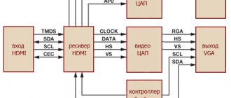
The USB interface began to be widely used about 20 years ago, to be precise, since the spring of 1997. It was then that the universal serial bus was implemented in hardware in many personal computer motherboards. Currently, this type of connecting peripherals to a PC is a standard, versions have been released that have significantly increased the data exchange speed, and new types of connectors have appeared. Let's try to understand the specifications, pinouts and other features of USB.
What are the advantages of Universal Serial Bus?
The introduction of this connection method made it possible:
- Quickly connect various peripheral devices to your PC, from the keyboard to external disk drives.
- Make full use of Plug&Play technology, which simplifies the connection and configuration of peripherals.
- Refusal of a number of outdated interfaces, which had a positive impact on the functionality of computing systems.
- The bus allows not only to transfer data, but also to supply power to connected devices, with a load current limit of 0.5 and 0.9 A for the old and new generations. This made it possible to use USB to charge phones, as well as connect various gadgets (mini fans, lights, etc.).
- It has become possible to manufacture mobile controllers, for example, a USB RJ-45 network card, electronic keys for entering and exiting the system
Purpose and types
The USB connector has a good set of functions. With its help, you can not only transfer large amounts of information at high speed, but also provide the device with power. The new interface quickly replaced old ports on computers, for example, PS/2. Now all peripherals are connected to the PC using USB ports.
To date, 3 versions of the USB connector have been created:
- Standard 1.1 - could not compete with faster interfaces. Using USB 1.1, it was possible to transmit information at a speed of no more than 12 Mbit/s. At that time, Apple already had an interface with a bandwidth of up to 400 Mbit/s.
- Version 2.0 is what the connector owes its popularity to. Speeds of up to 500 Mbit/s appealed not only to users, but also to manufacturers of electronic gadgets.
- Standard 3.0 - the maximum information exchange speed was 5 Gbit/s. Although the number of pins in this version of the USB connector has increased from 4 to 9, the shape of the connector has not changed, and it is compatible with previous standards.
Types of USB connectors - main differences and features
There are three specifications (versions) of this type of connection that are partially compatible with each other:
- The very first version that has become widespread is v 1. It is an improved modification of the previous version (1.0), which practically did not leave the prototype phase due to serious errors in the data transfer protocol. This specification has the following characteristics:
- Dual-mode data transfer at high and low speed (12.0 and 1.50 Mbps, respectively).
- Possibility of connecting more than a hundred different devices (including hubs).
- The maximum cord length is 3.0 and 5.0 m for high and low transfer speeds, respectively.
- The rated bus voltage is 5.0 V, the permissible load current of the connected equipment is 0.5 A.
Today this standard is practically not used due to its low throughput.
- The dominant second specification today... This standard is fully compatible with the previous modification. A distinctive feature is the presence of a high-speed data exchange protocol (up to 480.0 Mbit per second).
A clear demonstration of the advantages of USB 2.0 over other interfaces (transfer speed 60 MB per second, which corresponds to 480 Mbit per second).
Thanks to full hardware compatibility with the younger version, peripheral devices of this standard can be connected to the previous modification. True, the throughput will decrease up to 35-40 times, and in some cases more.
Since these versions are fully compatible, their cables and connectors are identical.
Please note that, despite the bandwidth specified in the specification, the actual data exchange speed in the second generation is somewhat lower (about 30-35 MB per second). This is due to the implementation of the protocol, which leads to delays between data packets. Since modern drives have a read speed four times higher than the throughput of the second modification, that is, it does not meet current requirements.
- The 3rd generation universal bus was developed specifically to solve problems of insufficient bandwidth. According to the specification, this modification is capable of exchanging information at a speed of 5.0 Gbit per second, which is almost three times the reading speed of modern drives. Plugs and sockets of the latest modification are usually marked blue to facilitate identification of belonging to this specification.
USB 3.0 connectors have a characteristic blue color.
Another feature of the third generation is an increase in the rated current to 0.9 A, which allows you to power a number of devices and eliminate the need for separate power supplies for them.
As for compatibility with the previous version, it is partially implemented; this will be discussed in detail below.
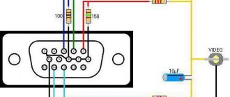
USB Type C pinout
USB Type is divided into A, B, B (mini), B (micro) and C.
USB Type A and B have 4 contacts each:
- +5V;
- D-;
- D+;
- GND.
To USB Type B mini and micro, as well as Type C, another contact is added - ID.
USB has a “plug” and a “socket”. On the pinout, the “socket” is on the left and the “plug” is on the right.
Notable Features of USB-C:
- There is a changeover connector. It is designed in such a way that the plug can be moved relative to the socket.
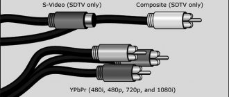
- There is support for USB 2.0, 3.0 and 3.1 Gen 2, as well as third-party protocols (for example, HDMI), in alternative mode.
Thanks to this, the devices are able to independently negotiate and determine the required power flow through the interface.
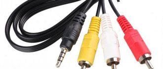
- USB Type C is capable of transmitting images and audio
- It can withstand high currents, so it is possible to power many devices at the same time.
Taking into account all the advantages described above, USB Type-C can be called a truly universal connector of the future. It is capable of replacing almost any existing connector. Now, for example, the Apple company produces laptop models equipped only with Type-C connectors.
Pinout of micro USB connector for charging the phone
Everyone has encountered a problem when the charger refuses to charge the phone, no matter how you twist it. There can be many options for this behavior: from burning out the insides of the adapter to lack of contact in the connector.
The USB Consortium has adopted a new standard known as micro-B, a smaller USB connector that will be used primarily on small portable devices where space is limited (such as cell phones). The micro USB connector is approximately half the height of the mini USB connector, allowing thinner devices to have USB access.
GSMA has accepted it as a universal charging solution, so 90% of new mobile phones will have this connector.
The pinout shows micro USB, which Samsung often uses. Here you can see that there are 5 contacts (ID is present), the counting goes from right to left, and there is also a jumper between the green (D+) and white (D-) contacts.
In the same Samsung you can find a jumper not only on white (D-) and green (D+), but also on black (GND) and purple (ID) using a resistor.
This is necessary in order to make the required voltage (this figure is different for all devices, but in most cases the resistance should be up to 200 kOhm).
Thanks to this, the device understands when to supply current and in what quantity.
Classification and pinout
Connectors are usually classified by type, there are only two of them:
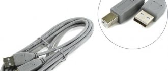
- A is a plug connected to the female socket installed on the PC system board or USB hub. Using this type of connection, you can connect a USB flash drive, keyboard, mouse, etc. These connections are fully compatible between the initial version and the second generation. With the latest modification, compatibility is partial, that is, devices and cables from earlier versions can be connected to third-generation sockets, but not vice versa.
Type A connectors - B – plug for connecting to a socket installed on a peripheral device, for example, a printer. The dimensions of the classic type B do not allow it to be used for connecting small-sized devices (for example, tablets, mobile phones, digital cameras, etc.). To correct the situation, two standard reduced modifications of type B were adopted: mini and micro USB.
Note that such convectors are compatible only between earlier modifications.
Various Type B Connector Models
In addition, there are extension cables for the ports of this interface. At one end there is a type A plug, and at the other there is a socket for it, that is, in fact, a “female” - “male” connection. Such cords can be very useful, for example, to connect a flash drive without crawling under the table to the system unit.
USB Extension Cable
Now let's look at how contacts are wired for each of the types listed above.
How to remake a plug with your own hands
Now you have a pinout diagram for all popular smartphones and tablets, so if you have the skill to work with a soldering iron, there will be no problems converting any standard USB connector to the type your device needs. Any standard charging that is based on the use of USB involves the use of only two wires - +5V and a common (negative) contact.
Just take any 220V/5V charging adapter and cut off the USB connector from it. The cut end is completely freed from the shield while the remaining four wires are stripped and tinned. Now we take a cable with a USB connector of the desired type, after which we also cut off the excess from it and carry out the same procedure. Now all that remains is to simply solder the wires together according to the diagram, after which each connection is insulated separately. The resulting case is wrapped on top with electrical tape or tape. You can fill it with hot glue - also a normal option.
Bonus: all other connectors (sockets) for mobile phones and their pinouts are available in a single large table -
.
USB 2.0 connector pinout (types A and B)
Since the physical plugs and sockets of early versions 1.1 and 2.0 do not differ from each other, we will present the wiring of the latter.
Figure 6. Wiring the plug and socket of type A connector
Designation:
- A – nest.
- B – plug.
- 1 – power supply +5.0 V.
- 2 and 3 signal wires.
- 4 – mass.
In the figure, the coloring of the contacts is shown according to the colors of the wire, and corresponds to the accepted specification.
Now let's look at the wiring of the classic socket B.
Wiring of plug and socket type B
Designation:
- A – plug connected to the socket on peripheral devices.
- B – socket on a peripheral device.
- 1 – power contact (+5 V).
- 2 and 3 – signal contacts.
- 4 – ground wire contact.
The colors of the contacts correspond to the accepted colors of the wires in the cord.
Micro-USB connector pinout
The Micro-USB cable has 5-pin connectors. A separate mounting wire in insulation of the desired color is supplied to them. To ensure that the plug fits accurately and tightly into the socket, the upper shielding part has a special chamfer. The micro USB pins are numbered 1 to 5 and read from right to left.
The pinouts of micro- and mini-USB connectors are identical; they are presented in the table:
| Wire number | Purpose | Color |
| 1 | VCC power supply 5V | red |
| 2 | data | white |
| 3 | data | green |
| 4 | ID function, for type A shorted to ground | |
| 5 | grounding | black |
USB 3.0 pinout (types A and B)
In the third generation, peripheral devices are connected via 10 (9 if there is no shielding braid) wires; accordingly, the number of contacts is also increased. But they are located in such a way that it is possible to connect devices of earlier generations. That is, the +5.0 V contacts, GND, D+ and D-, are located in the same way as in the previous version. The wiring for Type A socket is shown in the figure below.
Figure 8. Pinout of Type A connector in USB 3.0
Designation:
- A – plug.
- B – nest.
- 1, 2, 3, 4 – connectors fully correspond to the pinout of the plug for version 2.0 (see B in Fig. 6), the colors of the wires also match.
- 5 (SS_TX-) and 6 (SS_TX+) connectors for data transmission wires via the SUPER_SPEED protocol.
- 7 – ground (GND) for signal wires.
- 8 (SS_RX-) and 9 (SS_RX+) connectors for data receiving wires using the SUPER_SPEED protocol.
The colors in the figure correspond to those generally accepted for this standard.
As mentioned above, a plug from an earlier model can be inserted into the socket of this port; accordingly, the throughput will decrease. As for the plug of the third generation of the universal bus, it is impossible to insert it into the sockets of the early release.
Now let's look at the pinout for the type B socket. Unlike the previous type, such a socket is incompatible with any plug of earlier versions.
Wiring USB 3.0 type B
Designations:
A and B are plug and socket, respectively.
Digital signatures for contacts correspond to the description in Figure 8.
The color is as close as possible to the color markings of the wires in the cord.
Charger port classification
- SDP (Standard Downstream Ports) – data exchange and charging, allows current up to 0.5 A.
- CDP (Charging Downstream Ports) – data exchange and charging, allows current up to 1.5 A; hardware identification of the port type (enumeration) is performed before the gadget connects the data lines (D- and D+) to its USB transceiver.
- DCP (Dedicated Charging Ports) - charging only, allows current up to 1.5 A.
- ACA (Accessory Charger Adapter) - PD-OTG operation in Host mode is declared (with connection to PD peripherals - USB-Hub, mouse, keyboard, HDD and with the possibility of additional power supply), for some devices - with the ability to charge PD during OTG- sessions.
Micro USB connector pinout
To begin with, we present the wiring for this specification.
Micro USB v 2.0 connector wiring
As can be seen from the figure, this is a 5 pin connection; both the plug (A) and socket (B) have four contacts. Their purpose and digital and color designation correspond to the accepted standard, which was given above.
Description of the micro USB connector for version 3.0.
For this connection, a characteristically shaped 10 pin connector is used. In fact, it consists of two parts of 5 pin each, and one of them fully corresponds to the previous version of the interface. This implementation is somewhat confusing, especially considering the incompatibility of these types. Probably, the developers planned to make it possible to work with connectors of earlier modifications, but subsequently abandoned this idea or have not yet implemented it.
MicroUSB connector layout for version 3.0
The figure shows the pinout of the plug (A) and the appearance of the micro USB socket (B).
Contacts 1 to 5 fully correspond to the second generation micro connector, the purpose of the other contacts is as follows:
- 6 and 7 – data transmission via high-speed protocol (SS_TX- and SS_TX+, respectively).
- 8 – mass for high-speed information channels.
- 9 and 10 – data reception via high-speed protocol (SS_RX- and SS_RX+, respectively).
Pinout features
When talking about the pinout of a USB connector, you need to understand the symbols indicated on the diagrams. It’s worth starting with the type of connector - active (type A) or passive (type B). Using an active connector, information can be exchanged in two directions, and a passive connector only allows it to be received. You should also distinguish between two forms of connector:
- F - "mother".
- M - "dad".
USB connector
First, a few words need to be said about the compatibility of the three versions of the interface. Standards 1.1 and 2.0 are completely similar in design and differ only in the speed of information transfer. If one of the parties in the connection has a higher version, then work will be carried out at low speed. The OS will display the following message: “This device is capable of running faster.”
With compatibility between 3.0 and 2.0, everything is somewhat more complicated. A device or cable of the second version can be connected to the new connector, and backward compatibility exists only for active type A connectors. It should be noted that the USB interface allows you to supply a voltage of 5 V to the connected gadget with a current of no more than 0.5 A. For the USB standard 2.0, the color layout from left to right is as follows:
- Red - positive contact of constant voltage of 5 V.
- White - data-.
- Green - data+.
- Black is the common wire or ground.
The connector circuit is quite simple, and if necessary, repairing it will not be difficult. Since version 3.0 has increased the number of contacts, its pinout also differs from the previous standard. Thus, the color scheme of the contacts is as follows:
- Red - 5 V+.
- White - data-.
- Green - data+.
- Black is common.
- Purple - welcome.
- Orange - reception+.
- Without color - earth.
- Blue—transmission-.
- Yellow - transmission+.
Micro and mini connectors
Connectors of this form factor have five contacts, one of which is not always used. Conductors of green, black, red and white colors perform similar functions to USB 2.0. The mini-USB pinout corresponds to the micro-USB pinout. In type A connectors, the violet conductor is shorted to the black, but in passive connectors it is not used.
These connectors appeared due to the entry into the market of a large number of small devices. Since they are similar in appearance, users often have doubts about whether the connector belongs to a particular form factor. In addition to some differences in dimensions, micro-USBs have latches on the back side.
Miniaturization of the connector had a negative impact on reliability. Although mini-USB has a large resource, after a fairly short period of time it begins to dangle, but does not fall out of the socket. Micro-USB is a modified version of mini-USB. Thanks to the improved fastening, it turned out to be more reliable. Since 2011, this connector has become a unified standard for charging all mobile devices.
However, manufacturers are making some changes to the scheme. Thus, the pinout of the micro-USB connector for charging the iPhone involves two changes compared to the standard one. In these devices, the red and white wires are connected to the black through a resistance of 50 kOhm, and to the white - 75 kOhm. There are also differences from the standard for Samsung Galaxy smartphones. In it, the white and green conductors are closed, and pin 5 is connected to pin 4 using a 200 kOhm resistor.
Knowing the pinout of different types of USB connectors, you can find and fix the problem. Most often, this is required in a situation where the “native” charger has failed, but the user has a power supply from a smartphone from another manufacturer.
Mini USB pinout
This connection option is used only in early versions of the interface; in the third generation this type is not used.
Mini USB connector pinout
As you can see, the wiring of the plug and socket is almost identical to the micro USB, respectively, the color scheme of the wires and the contact numbers are also the same. Actually, the differences are only in shape and size.
In this article we have presented only standard types of connections; many manufacturers of digital equipment practice introducing their own standards; there you can find connectors for 7 pin, 8 pin, etc. This introduces certain difficulties, especially when the question arises of finding a charger for a mobile phone. It should also be noted that products are in no hurry to tell how the USB pinout is done in such contactors. But, as a rule, this information is easy to find on thematic forums.
USB power
Any USB connector supplies a voltage of 5 Volts, and the current cannot exceed 0.5 Amperes (for USB 3.0 – 0.9 Amperes). In practice, this means that the maximum power of the connected device can be no more than 2.5 Watts (4.5 for USB 3.0). Therefore, there will be no problems when connecting low-power and portable devices - players, phones, flash drives and memory cards. But all large-sized and massive equipment has external power supply from the network.
Now let's move on to the types of connectors. I will not consider completely exotic options, but will only talk about the most popular and frequently used plugs. Affiliation with a specific USB version will be indicated in brackets.
This is the most common and most recognizable connector currently in existence. Most devices connected via USB have it. Mice, flash drives, keyboards, cameras and much more are all equipped with USB Type A, which dates back to the 90s. One of the most important advantages of this port is reliability. It can survive a fairly large number of connections, does not fall apart, and has truly deserved to become the most common means of connecting everything possible. Despite its rectangular shape, it cannot be stuck in with the reverse side; there is “fool protection”. However, it is not suitable for portable devices, since it has quite large dimensions, which ultimately led to the appearance of smaller modifications.
General information about USB
The USB cable consists of four conductors made of copper. These are two conductors intended for power supply, and the remaining conductors are in a twisted pair. This kit also includes a grounded braid.
Let's now take a little look at the host. It acts as a special controller, which is programmed and controlled. Its task: to ensure the operation of the interface. By the way, the controller can most often be found in a microcircuit. A hub is required to connect the controller to other devices.
But in order to connect external devices to the hub, ports are used, at the end of which there are connectors. Cables help USB devices connect to ports. The device can be powered differently: from the bus or some kind of external power source.
It only takes a few minutes to get started and you can get started. First, the signal to start working is sent to the cable hub
, which further informs that the equipment is ready for operation.
But it is worth remembering one rule. Whenever you start pinouting a device, first determine what the pinout is on your cable. The USB connector helps you connect all external devices to your computer. This modern connection method replaces all those methods that were previously available. This connector provides additional options
: When operating computer equipment, any devices can be connected and immediately put into operation. It may also affect the charging operation.
USB Specification
There were the first preliminary versions of USB, which began to be released in November 1994. This went on for a year. And after that, new USB models began to come out
which are still in use today.
Today we can talk about the following models:
- USB 1.0. This model was released in January 1996.
- USB 1.1. This specification was released in September 1998.
- USB 2.0. This model was released in 2000.
Charging the battery via Micro USB
In addition, it supplies a 5-volt power supply to charge the battery of wearable gadgets. Since almost all modern lithium batteries have an operating voltage of 3.7 V, the 5 V supplied via Micro-USB is excellent for replenishing energy. True, not directly to the battery, but through the charger converter.
I’m glad that the connector pinout is the same for all smartphone manufacturers - Samsung, LG, Huaway and others. Thus, a 220 V charger-adapter from one phone is most often suitable for charging another without changing the pinout.
- The main advantage of the Micro-USB connector over other types is the ability to connect Plug&Play devices without the need to restart the computer or manually install drivers. Devices can be connected while the computer is running and disconnected without having to press any buttons.
The main thing is not to confuse the difference between Micro USB and Mini USB.
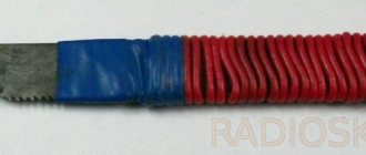
The main confusion that arises among users is between Mini USB and Micro USB, which are indeed a bit similar. The first one is slightly larger, and the second one has special latches on the back side. It is by the latches that you can always distinguish these two connectors. Otherwise they are identical. And since there are a lot of devices with both, it is better to have both cables - then there will be no problems connecting any modern portable equipment.
Mini USB on the left, Micro USB on the right. Mini USB is much thicker, which prevents it from being used in compact, thin devices. Micro USB is easily recognized by two notches that hold the plug tightly when connected.
Three brothers of the same family. Mini USB and Micro USB are much thinner than usual. On the other hand, the “little ones” are inferior in reliability to their older comrades.
USB cables have different physical ends. It depends on what device it is connected to. There are connections to the device itself and to the host. Moreover, USB can be with or without a cable. Another option is possible: the cable is built into the device itself. The cable is necessary to form an interface between the device and the host.
But after some time, the developers of such a computer interface as USB still had low speed
in order to use external hard drives and other devices whose speed was much greater. Therefore, the creators of USB had to change the device so that a new model was obtained. Now the speed of the third type of USB has become ten times faster. Of course, this also affected charging.
Conclusions and useful video on the topic
The video below explains the main points of pinout of connectors of the 2.0 series and others, and visually explains individual details of the production of soldering procedures.
Having complete information on the pinout of Universal Serial Bus connectors, you can always cope with a technical problem associated with conductor defects. This information will also come in handy if you need to connect some digital devices in a non-standard way.
Would you like to supplement the above material with useful comments or valuable tips on do-it-yourself desoldering? Write comments in the block below, add, if necessary, unique photographic materials.
Maybe you still have questions after reading the article? Ask them here - our experts and competent site visitors will try to clarify unclear points.
Technical characteristics of each model
The first model is USB 1.0. This specification distinguishes two operating modes:
- Low bandwidth.
- With high throughput.
The maximum cable length allowed in this model for the first operating mode is three meters, and for the second operating mode it reaches five meters. If you want to connect several devices, you can connect up to 127 of them.
The technical characteristics of the USB 1.1 model correspond to the first, but all the problems and errors that arose during its use have been corrected. By the way, this is the first model that gained wide popularity
and spread quickly.
The third model is USB 2.0. There are three operating modes for it, where mice, a joystick, gamepads, and a keyboard can be used, as well as video devices and devices that store information.