Almost all modern video cards use the same 15-pin VGA connector that was used in the original IBM video cards. VGA stands for Video Graphics Adapter or Video Graphics Array.
There are at least four versions of the VGA connector. These are three-row fifteen-pin connector DE-15 from original video cards, which is also called mini-sub D15, and connector DDC2. Less common and less capable are the 9-pin VGA and Mini-VGA used for laptops.
VGA connectors pinout
The table below shows the purpose of the modern 15-pin VGA VESA DDC2 connector. VESA stands for Video Electronics Standard Association. VGA DDC2 pinout :
| Pin | Name | Direction | Description |
| 1 | Red | > | Red video (75 Ohm, 0.7 V) |
| 2 | Green | > | Green video (75 Ohm, 0.7 V) |
| 3 | Blue | > | Blue video (75 Ohm, 0.7 V) |
| 4 | RES | Not used | |
| 5 | GND | —— | Earth |
| 6 | RGND | —— | Land of red |
| 7 | GGND | —— | Land of green |
| 8 | BGND | —— | Land of Blue |
| 9 | +5V | > | Additional +5V from V/card |
| 10 | SGND | —— | Earth Synchronization |
| 11 | ID0 | < | Monitor ID Bit 0 (optional) |
| 12 | S.D.A. | < | I2C bidirectional data line |
| 13 | HSYNC or CSYNC | > | Horizontal Sync (or Composite Sync) |
| 14 | VSYNC | > | Vertical Sync |
| 15 | SCL | < | Clock frequency 15 SCL I2C in DDC2, Monitor ID3 in DDC1 |
Note: The direction of the signal is relative to the computer and monitor. All signals on the VGA pins, except R, G, B, are TTL level signals. The basic VGA modes (80x25 in text mode and 640x480 in graphics mode) are still supported by all modern graphics cards, regardless of the additional modes supported by those cards. VGA Video Specifications : 256 KB of video memory 16-color and 256-color modes 262,144-color color palette (six bits for red, green and blue) Selectable clock frequency 25.175 MHz or 28.322 MHz Maximum 800 pixels horizontal Maximum 600 lines (interlaced) Frequency frames up to 70 Hz Reverse interruption Plane mode: up to 16 colors (4-bit planes) Packed pixel mode: 256 colors (13h mode) Hardware support for smooth scrolling Supports some raster operations Fast shifter Supports split screen Amplitude 0.7 V 75 Ohms resistance at both ends (18.7 mA - 13 mW)
VGA pinout - correct monitor connector pinout
VGA pinout .
The VGA monitor connector is currently the most famous and popular monitor interface, which was developed by IBM more than thirty years ago. But even despite this, the VGA video standard can be found installed on most modern computer equipment. Especially on computers where it is necessary to display video in a simplified graphic mode, with a resolution of 640x480. Absolutely all graphics cards produced in the world are compatible with this mode. The process of outputting high-resolution video information occurs exclusively after the graphics adapter drivers are loaded during the operating system startup.
Pinout of the VGA wire according to its color coding is very helpful in some cases, for example: When performing independent testing of conductors for breaks or, if necessary, increasing the length of the wire. Note: The industry produces VGA cables with a length of about thirty meters.
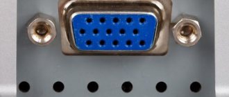
A fifteen-pin VGA connector, the design of which is a trapezoid shape with pins arranged in a three-row pattern, each row having five pins. To ensure correct connection of complementary connectors, the contacts in the block are installed in an asymmetrical order. Such a device, due to its shape, guarantees correct cable connection. The numbering sequence of the output contacts should be designated as shown in the picture below:
VGA pinout according to color coding
Mini VGA connector pinout
Resoldering VGA connector
Those who own a significant amount of audio and video equipment are faced with a choice: make it yourself or purchase an adapter from the store that will convert signals of different types. Needless to say, factory devices cost a lot, but you can often do without them. And within the article we will talk about how to make a VGA to RCA adapter. Frequently asked questions will also be answered.
Differences from EGA
VGA is exactly the same as EGA (including in-plane video memory in 16-color modes and a sequencer for processor access to it), with the following exceptions:
- a different connector and cable to the monitor (and other monitors), analog, and not 2 bits per color. This connector and cable remained unchanged for about 15 years (until the advent of digital packet-based technologies DVI, HDMI and DisplayPort, which came from the world of consumer video equipment) and were then used in much higher resolutions. Even standard VGA monitors were often capable of displaying 800x600 mode when used with a more modern video card (everything depended on the quality of the monitor’s scan units and their ability not to disrupt generation at such increased frequencies). Currently (all modern video cards are compatible with VGA from top to bottom), the word “VGA” in everyday life means precisely this type of monitor connection, now outdated, but still relevant.
- 18-bit colors in the palette instead of 6-bit, such a rich set made it possible, for example, to implement night, bad weather, “enchanted” modes and flickering colors in games with just a palette (as in the game “Ultima VII”)
- the presence of 256-color modes, the standard one is 320x200, undocumented (in fact, documented in the documentation for VGA hardware, but not included in the BIOS and its documentation) tricks it was possible to get 320x240 (square pixels, the so-called “VGA mode” -X") and higher
- maximum 16-color mode - 640x480 (square pixels)
- in all 200-line graphic modes, the scan line was repeated 2 times, which gave 400 physical scan lines of the monitor, which greatly improved the picture quality even in lower modes (no gaps between the scan lines).
- the height of the character generator cell is 16 scan lines, not 14, like the EGA, which gave the same 400 scan lines in all text modes (except for modes compatible with the EGA character generator). Thus, VGA always used 400 scan lines, except for the two higher 16-color modes, where there were 480 and 350. VGA-X mode also used 480 lines.
- All registers (palette, sequencer, etc.) are readable, EGA had a number of “write-only” registers (for example, palette).
What is a VGA RCA adapter
The circuit of this device may seem complicated, but only until you understand it. What is this device? This is an adapter from tulips (RCA connectors) of analog video output to VGA D-Sub for 15 pins. The device reviewed here can be used to connect a DVD player or satellite tuner to a multimedia projector. Of course, provided that it is not possible to work directly using the same type of cable, which is usually common in cheap or outdated devices.
What is the idea?
How to implement such an idea? You need a computer cable (twisted pair type CAT5/CAT5e) designed to transmit video signals. We will use it because the transmission is carried out over a distance of fifty meters without loss of quality.
First, we need to acquire three RCA connectors and one D-Sub15 pin (this is a plug), as well as a twisted pair cable. The last part is better to use shielded STP than UTP. But this one is more difficult to get, which affects the price. Therefore, the issue of possibilities and desires is considered here. There is no particular difference between the elements, but there is one nuance: it is better to use UTP if the cable length is less than 10 meters. If the distance is greater, then it would still be better to find STP.
Why does TV need a computer?
Before we tell you how to connect a computer to a TV via a “tulip”, let’s answer this question. First, let's look at a regular monitor screen and take a look at the TV display. The latter, as a rule, significantly benefits from a larger diagonal and is not located somewhere in the corner on the desktop, but opposite a comfortable sofa or armchair, where it can easily fit, if not a large company, then a friend or girlfriend for sure.
Watching videos, photos and gaming - all this looks much more pleasant on a TV screen than on a modest monitor: there is no need to look at the details, use speakers, and personal PCs have not yet acquired remote controls.
The most common reason that motivates an owner to connect a TV to a computer via an RCA cable (“tulips”) is watching videos. But in fact, you can display the same picture on the LCD screen as on the monitor. And it doesn't have to be a movie. Therefore, you should not forget about photos, the Internet and games.
All kinds of car and flight simulators, arcades, shooters and even strategies feel great on the big screen, and gaming becomes truly enjoyable. Also, no one forbids you to surf the web from the comfort of your sofa.
Pinout
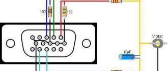
How to pinout a 15 pin D-Sub connector? The numbers go from left to right:
1 – RY (Pr). 2 – Y. 3 – BY (Pb). 4 – Ground – Brown. 5 – Ground – WhtBrown. 6 – Ground RY (Pr) – WhtRed. 7 – Ground Y – WhtGreen. 8 – Ground BY (Pb) – WhtBlue. 9 – Not needed. 10 – Ground. 11 – Not needed. 12 – DDC DAT. 13 – Horizontal Synchronization. 14 – Vertical Synchronization. 15 – DDC Clock.
For the VGA RCA adapter cable we need six pins out of the fifteen presented. How to properly wire connectors and contacts? Check out this picture and you will understand how and what to do.
So let's see what happened. If everything was soldered correctly, then you now have an adapter that can supply a video signal to VGA D-Sub on the 15 pins of the projector. You can see approximately what the final product should look like in the photographs presented in the article.
Video Memory Layout
The video memory consists of four 'planes' (individual units) of memory, each with a size of 64KB, giving the VGA 256k of video memory. Connected to it is the Sequencer, which interprets this memory to generate colors which are fed to the subsequent stages. The way colors are organized in this memory mainly depends on the color depth.
Specific details about how memory is accessed from the host is can be found by reading about the Graphics Controller, detailed information about video memory is rendered can be found by reading about the Sequencer.
Memory Layout in 16-color graphics modes
16 colors means there are 4 bits used per color. The VGA has four planes, and for each pixel, and each plane holds one bit of each pixel drawn. Since the information for each pixel is scattered over four memory locations, this is the most difficult memory model.
Bit 7 of each address contains information about the first pixel, Bit 6 has information about the next pixel, and so on.
Plane 0 contains the first bits of all pixels, Plane 1 the second bits and so on.
Example:
| one byte | ||||||||
| Bits | 7 | 6 | 5 | 4 | 3 | 2 | 1 | |
| Plane 0 | 1 | 1 | 1 | 1 | ||||
| Plane 1 | 1 | 1 | 1 | 1 | ||||
| Plane 2 | 1 | 1 | 1 | 1 | ||||
| Plane 3 | 1 | 1 | 1 | 1 | ||||
| Colors displayed | 0000 (0) | 1100 (12) | 0110 (6) | 1010 (10) | 0011 (3) | 1111 (15) | 0101 (5) | 1001 (9) |
The Plane Write Enable register is used to choose the plane to be written, then the memory can be written by accessing the corresponding address in memory.
Memory Layout in 256-color graphics modes
In this mode, each byte of video memory describes exactly one pixel. Pixels are generated by increasing address in linear mode, with all colors taken from plane 0. In planar mode (Also known as Mode X) each address describes 4 consecutive pixels, one from each plane. Plane 0 describing the first pixel, plane 1 the next, and so on. Technically speaking this is what always happens, but the standard 320x200x256 mode “chains” the planes such that 2 lowest order bits select the plane and the memory thus appears linear.
In linear mode, each byte in host memory corresponds to one pixel on the display, making this mode very easy to use. Mode X requires the use of Plane Write Enable register to select the plane to be written.
Memory Layout in text modes
In text mode, the screen is divided into character cells rather than pixels. Only three of the four planes are actually in use. Plane 0 contains the character codes for each cell, Plane 1 contains the respective attributes.
Plane 2 contains the font data. For each of the 256 available characters this plane has 32 bytes reserved. Each byte represents one horizontal cross section through each character. The first byte of each group defines the top line, each next byte describes the rows below it. For every set bit, the foreground color is used, For every cleared bit, the background color is used.
Although 32 bytes are reserved for each character, only 16, 14, or 8 of them are commonly used, depending on the character height.
Planes 0 and 1 are accessible from the host by writing to the video memory range. Plane 0 is accessed on even addresses, plane 1 is accessed on odd addresses, with each consecutive 16-bit value describing the next character. Accessing plane 2 to change fonts requires changes in addressing logic.
Memory Layout in 4-color modes
The CGA was limited to 4 concurrent colors, with two bits each. The EGA adds two extra bits by adding a pair of extra planes, increasing from the old two to the current four planes per pixel. If you want a 4-color mode that means you just should not touch planes 2 + 3.
Todo: determine the b/w/d, shift mode and odd/even mode for CGA compatibility (guesstimated at word mode, interleaved shift, odd/even enabled, ie equivalent to text mode except for the alphanumeric bit)
Examination
Wire pairs with RCA plugs soldered at the ends can be usefully compressed with heat shrink to obtain greater rigidity. In general, now you can connect the result of your work and enjoy it (if everything was soldered together as needed). Paired wires, at the ends of which RCA plugs are attached, can be crimped with heat shrink to obtain greater rigidity.
In this case, we used a satellite tuner with a 3 RCA component video output as a signal source and a Sanyo multimedia projector, which did not have a separate video input of the same type. If at the moment it is not possible to verify the functionality of the resulting adapter, then you can only carefully inspect the entire structure and make sure that there were no omissions, and everything is soldered as indicated in the article.
What you need to understand
You should be aware that the adapter in question can ensure the operation and full functioning of a device that has a VGA video input only if it can automatically detect the type of incoming video signal. An indicator of this will be the ability to select the mode in which data will be transmitted to RGB/YPbPr. Usage will be positively impacted by sending these types of signals. Why is that?
The fact is that RGB and HV.sync (for example, data coming from the output of a personal computer’s video card) are converted to RGB, which has sync pulses in the green channel (Y). It, in turn, turns into the color-difference YPbPr. And as a result, we can conclude that these signals are not the same thing, although they can convey the same information. Therefore, carefully study what a VGA RCA adapter looks like.
What adapters can be made using twisted pair?
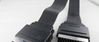
- VGA extenders are special cables that have D-Sub 15 pin connectors on both ends, while their input and output use the same technology.
- RCA (3xRCA) is used to transmit component video signals. There are three connectors at each end. Used when working with a DVD player and TV.
- RCA (D-Sub15pin) was discussed a little higher. Here are the components Y, Pr, Pb in VGA.
- To transmit analog audio, two pairs of stereo signals can be used simultaneously (4 RCA connectors at each end).
VGA connector pinout
The pinout of the VGA interface connector is shown below. The first three pins are designed to transmit an analog signal of three primary RGB colors (1-red, 2-green and 3-blue). The red, green, and blue signal lines have their own negative wires (6, 7, and 8). Pins 13 and 14 are intended for horizontal and vertical synchronization, respectively.
The VGA connector in appearance to the COM port connector (DB9). But unlike DB9, the VGA connector has 15 pins arranged in three rows of 5 pins in each row. In addition to color rendering signals (RGB) and synchronization signals, the VGA connector also has an I2C digital interface, designed for two-way communication between the video controller and the monitor. This interface (I2C) gives VGA sufficient versatility.
It should be noted that I2C was not implemented in the first versions of the VGA standard, but was added much later with the advent of the VESA DDC2 standard. Using the I2C interface, the controller and monitor can exchange technical information, such as frequency availability and resolution, to prevent operational incompatibilities.
Characteristics
Let's now move on to the specifications of the d-sub connector:
- 256 KB video RAM. Serves as buffer memory.
- Sixteen-color and 256 color modes.
- Color palette of 262,144 colors.
- Selectable frequency of 25.175 or 28.322 megahertz.
- Maximum 800 horizontal pixels (possibly more now).
- Maximum 600 vertical pixels (can also be more).
- Update rate up to 70 times per second.
- Hardware support for smooth scrolling.
- Support for some raster operations.
- Split screen support.
As mentioned above, the d-sub cable uses a certain technology called EDDC, which stands for Enhanced display data channel. This technology is designed for two-way communication between a computer, or more precisely, a video adapter and a monitor. The description of the d-sub pinout mentioned a binary number. This very number is the key to the internal memory of the monitor and it is transmitted to the computer so that it can read the necessary information from the internal memory of the monitor. And communication itself is necessary for more precise adjustment of the monitor for better performance and picture quality.
Also important information is that d-sub is an analog technology, so it carries an analog signal. It follows that the quality of such a signal directly depends on the quality of the cable itself and the wiring. The quality of the cable depends on the thickness of the cable, the quality of the insulation, the length of the cable and the quality of the conductor used.
From this we can conclude that truly high-quality d-sub cables cannot be cheap, because they are expensive to manufacture
The quality of the cable depends on the thickness of the cable, the quality of the insulation, the length of the cable and the quality of the conductor used. From this we can conclude that truly high-quality d-sub cables cannot be cheap, because they are expensive to manufacture.
In conclusion, the fifteen-pin d-sub is a common connector that transmits an analog signal, found in almost all current computer equipment. Its specifications are acceptable for most of the audience. The biggest nuance is that this technology is already quite old and has practically outlived its usefulness. It is being replaced by new connectors that carry a digital signal instead of an analog signal.
Monitor ID Bit 0
DDC Serial Data Line
Horizontal Sync (or Composite Sync)
DDC Data Clock Line (clock frequency for DDC)
Knowing the pinout of these connectors, you can easily solder a DVI-VGA or VGA-DVI adapter.
Diagram of such an adapter