S-Video Cable Technology Background
Standard analog television signals go through several processing steps along the way, each of which discards information and reduces the quality of the resulting images.
The image is initially captured in RGB form and then distributed into three signals known as YPbPr. The first of these signals is called Y, and is created from all three source signals based on a formula that creates the overall brightness of the image, or brightness. This signal corresponds to a traditional black and white television signal, and the Y/C encoding method is the key to ensuring backward compatibility. Once the Y signal is received, it is subtracted from the blue signal to obtain Pb and the red signal to obtain Pr. To restore the original RGB information for display, the signals are mixed with Y to produce the original blue and red, and then the sum of them is mixed with Y to restore green.
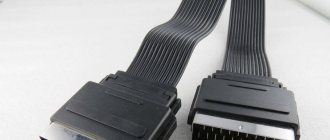
Scart pinout - correct pinout
Scart pinout - in the early 80s, the French joint company of radio and television developers designed a multi-pin SCART connector. Using this audio-video interface, it became possible to broadcast data received from RGB signal sources. This device, which provides excellent video quality, quickly became a fairly popular connector in Europe.
Read also: What do lathes and drilling machines have in common?
Somewhat later, this 21-pin connector found its application in players and video recorders produced by famous world brands. There are currently many popular systems for exchanging information using SCART.
In terms of design, the connector was developed to perform switching of various types of data in digital and analog format. This includes the transmission of audio and video signals, with the help of just one such connector it has become possible to record and play video content. In addition, a command transmission function is available to control the multimedia device during its setup.
Design features and scart pinout
The pinout of the scart connector is made according to a 2-component asymmetrical circuit; double-row spring-loaded male contacts transmit signals (20 are signal paths and 1 for protection). The outer housing of the contact connector has a characteristic shape that serves as a kind of key. It is this structural protrusion that guarantees the correct connection of the SCART; if it is unfolded during connection, the connection will be impossible.
The pinout of the SCART connector is carried out by installing odd numbers of contact blades at the bottom of the connector, while the cable key will be on the right side. The upper row of contacts, which have even designation numbers, is made with some offset relative to the lower row. It is this arrangement of the “knives” that prevents the connector from being connected in the opposite direction. The order of signal data through the contacts is shown in the table below. The protective wire, placed in a braided shield, is connected to 21 contacts.
| Contact no. | Purpose | Signal level, circuit resistance |
| 1 | Right channel audio output (mono) | Veff. = 0.2-2.0V, R 10kOhm |
| 3 | left channel audio output | Veff. = 0.2-2.0V, R 10kOhm |
| 7 | “BLUE” signal input/output | swing 0.7 V VDC = 0-2.0 V, R=75 Ohm |
| 8 | TV/VIDEO switching voltage input/output | Voff = 0 - 2.0 V, Von. = 9.5 - 12V, Rinput. > 10kOhm, Rout. Making a SCART cable with your own hands |
The need to manufacture a connector with a SCART connector at home may be caused by the need to create a multimedia complex for the home. And the pinout of the scart connector is done according to the table presented. When making a SCART connector yourself, it is not necessary to use all the contacts; you can connect only the ones you need. The place where the wire is soldered to the contact should be placed in a casing, possibly with heat-shrinkable properties.
SCART, as a unified connector, was first introduced by a French company. It was created to optimize signals from devices from various manufacturers. Thanks to the creation of a single format, users had the opportunity to buy models of household appliances from different brands, thereby allowing them to make a choice in favor of comfort, convenience, reliability and practicality.
Read also: Device for sharpening drills at home
The introduction of the universal connector was carried out intensively, by banning, starting in 1981, the production of equipment with other types of connections. The new format was introduced as mandatory for all manufacturers without exception. But at the same time, SCART began to be actively used throughout Europe only 3 years later, becoming a standard regulated by EN 50049-1. Due to its format and design, the connector has received many common names, such as comb and ratchet.
Problem and solution
A signal with three components is easier to translate than the original three-signal RGB, so additional processing is required. The first step is to combine Pb and Pr to form the C signal for chrominance. The phase and amplitude of the signal represent the two original signals. This signal is bandwidth limited to meet broadcast requirements. The resulting Y and C signals are mixed together to create composite video. To play composite video, the Y and C signals must be separated, and this is difficult to do without adding artifacts.
Each of these steps is subject to intentional or unavoidable loss of quality. To preserve this quality in the final image, it is desirable to eliminate as many encoding/decoding steps as possible. The S-Video cable eliminates the final mixing of C with Y and subsequent separation during playback.
Signal
An S-video cable carries the video signal using two synchronized signals and ground pairs called Y and C.
- Y is the signal that carries the luminance or black and white image, including the clock pulses.
- C is the chrominance signal, which carries the color or coloration of the image. This signal contains both the saturation and hue of the video.
The luminance signal transmits horizontal and vertical sync pulses in the same way as a composite video signal. Luma is the signal that carries the luminance after gamma correction and is therefore called Y due to its resemblance to a lowercase Greek letter
Connector pinout
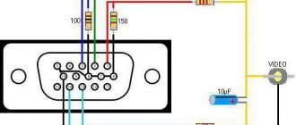
Even such an attractive connector as SCART cannot be used indefinitely. It was replaced by an S-Video connection. It is still widely used in various technologies. To connect to SCART, you can use widely used adapters. The wiring diagram is shown in the picture below.
But an even simpler solution is becoming more widespread - RCA. Separate connection involves the use of yellow, red and white plugs. The yellow and white lines are responsible for stereo audio. The red channel supplies the video signal to the TV. Wiring into “tulips” is carried out according to the diagram shown in the following photo.
Quite often you have to solve another problem - how to connect the old connector and modern HDMI. In this case, you won’t be able to limit yourself to conductors and adapters. You will have to use a device that will “translate” HDMI digital signals into analog and vice versa. Independent production of such equipment is impossible or extremely difficult.
It would be best to buy a ready-made converter of an industrial standard; it is usually small in size and can be easily placed behind the TV.
For SCART connectors, see below.
Comparative characteristics
In a composite video signal, signals coexist at different frequencies. The luminance signal must be a low-pass filter that dulls the image. Because the S-Video cable supports these parameters as separate signals, low-pass filtering for brightness is not necessary. Chroma still has limited bandwidth compared to component video.
Compared to component video, which carries an identical luminance signal but separates the color difference signals into Cb/Pb and Cr/Pr, the color resolution of S-Video cable is limited to modulation at a frequency of 3.57 to 4.43 megahertz.
With S-Video, the signals are separated along the cable, so no low-pass filtering is required. This increases the luminance transmission bandwidth, suppresses the problem of color crosstalk, and leaves more video information unchanged, thus improving image reproduction compared to composite video.
Because of the separation of video into luminance and color components, S-Video is sometimes considered a type of component video signal. What makes S-Video different from these higher component video schemes is that S-Video conveys color information as a single signal. This means that colors must be encoded, and therefore NTSC, PAL and SECAM signals are distinguished in S-Video. Therefore, for full compatibility, the devices used must not only be S-Video compatible, but also color code compatible.
Switching the video part of the complex
Let's continue the conversation.
This article will focus on switching video signals between sources and display device(s). Types of video signal transmission and, of course, the problem of making homemade cables will also be considered. So let's take a look at the inputs to see which ones are hot and which ones aren't. Unfortunately, composite video does not have high resolution. The trio has the bandwidth to carry a high-resolution signal, although the audio signal must come through a different connection.This is an analog signal without sound, but you can get high quality images. However, unlike your computer, you can't easily install software to use the new devices you connect. Optical digital audio output is more commonly used than coaxial digital audio output, but you must be sure that your receiver has a compatible input.
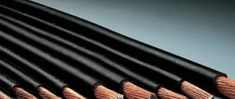
Cables
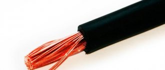
In fact, regardless of the type of analog video signal (composite, S-Video, RGB, component), the conductor is structurally a coaxial cable with a characteristic impedance of 75 Ohms. Depending on the type of video signal, there can be either one such cable, or several such cables are used to transmit the signal.
However, there are a huge number of varieties of practical implementation of this design. The center conductor may be a thick solid copper strand, may consist of many thin copper or silver-plated copper strands, and so on. The screen can be single, double or even triple, and can consist of wire, or wire in combination with foil or foil-coated plastic. The cable itself can be quite impressive and thick, or it can be very thin and inconspicuous. In general, there are many options here. And the most interesting thing is that it is quite difficult to say for sure which design provides guaranteed high image quality when transmitting an analog video signal - each manufacturer has its own methods and proprietary technologies. Some manage to make excellent cables consisting only of a stranded copper conductor and one copper screen. And someone makes a super-sophisticated cable using expensive materials, and the image quality does not live up to expectations, given the considerable cost of such a cable. That is, when choosing a cable, you should under no circumstances exclude the “image factor” and blindly trust the phrase “expensive means high quality.” However, it’s not all that scary, since most well-known “cable manufacturers” still have a well-deserved reputation as a conscientious manufacturer, which means that if you buy a cable from a well-known manufacturer that has proven itself well in the production of cables, you can hardly go wrong. At least it’s better than buying a cable from an unknown manufacturer, which, according to a seller on the market, is “much cooler than all these fancy branded ones.”
Can you at least give a few examples of trusted video cable manufacturers?
Supra, Wire World, Straight Wire, Canare, Monitor cable, QED, Ixos, Liberty. Of course, this is not a list, but brands named “at random”. I remembered, as you understand, not all of them...
Types and methods of analog video signal transmission
Composite
Since the most widespread is relatively inexpensive video equipment and budget-class TVs, the most widespread among people so far is the method of transmitting a video signal, where all its components are transmitted in mixed form over one single coaxial cable. This video signal is called “composite video”. And if in the era of the dominance of VHS cassettes this method of transmitting a video signal could be considered quite acceptable in quality, since the VHS cassette itself (in comparison with DVD, for example) cannot boast of a high-quality, clear image, then with the advent of inexpensive DVD players The composite video signal, if not doomed to death, at least began to fade into the background even in the class of budget equipment (it has not been used in expensive household video equipment for a long time). Now only VHS players/cassette recorders have a composite video output (in fact, they have never had and never will have another low-frequency video output except for a composite one), and karaoke set-top boxes. The vast majority of other devices, such as DVD players, modern video cameras, satellite receivers, and so on, already have much higher quality video outputs, where the components of the video signal are transmitted separately from each other. Although, in most modern devices, the composite video output is still present, so as not to deprive the user of the ability to connect the device to “less advanced” display devices. For example, many modern TVs with small screen diagonals (14″-21″), not to mention previously released models, still only have a composite video input.
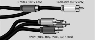
Typically, the output and input of a composite video signal is made in the form of a yellow RCA socket (in the photo the connector is in the lower left corner), or can be transmitted through a universal one.
The cable used to transmit a composite video signal consists of 1 coaxial cable with RCA (“tulip”) connectors at the ends.
S-Video
This type of video signal provides separate transmission of a luminance (Y) signal and two combined chrominance (C) signals via independent cables. The standard for this type of connection is a round 4-pin connector. S-Video transmission can also be organized via Scart
Compared to a composite video signal, connecting via S-Video provides some improvement in image clarity and stability, and to a lesser extent in color rendition. However, these improvements will be noticeable only when using a high-quality source (DVD player, high-quality satellite receiver, etc.) together with a sufficiently large diagonal screen (25″ or more). With a TV screen diagonal of 21″ (or less), the difference between a composite video signal and S-Video may not be so obvious, since much depends on the quality of the TV itself.
Component
Or another name - color difference (Y»PbPr or in other words YUV, YIQ). To transmit the components, three independent coaxial cables are used, where one cable (Y) transmits signals in the ratio 0.299R + 0.5876G + 0.114V, the other (Pr) transmits red minus brightness (R-Y), and the third ( Br) — blue minus brightness (BY). The connectors at the ends of the cable are usually RCA or BNC.
And here is what the component video output of a DVD player usually looks like.
The picture quality when connected via a component is radically (for the better) different from S-Video and, even more so, composite. Here the improvements are immediately visible: the picture is clearer and more stable with accurate color reproduction. The advantages of a component connection will be especially obvious when using high-quality video signal sources and large screens (29″-36″ TVs, good plasma panels, large-screen projectors).
RGB
In this case, separate transmission of three primary colors and a synchronization signal is used. To be precise, this type of video signal is called RGBS (Red, Green, Blue, Sync). Information is transmitted via independent cables. This can be 3 or 4 separate coaxial cables (in the case of 3 cables, the sync signal goes along with the green) with RCA or BNC connectors, or RGBS can be transmitted via.
There is also an even more complex variety of RGB, where not 3 or 4, but 5 cables are used to transmit signals, since the horizontal and vertical sync signals are transmitted separately from each other. This variety is called RGBHV (Red, Green, Blue, H-Sync, V-Sync). It is no longer possible to find RGBHV in a Scart cable, since such a video signal usually uses separate coaxial cables with RCA or BNC connectors, or one VGA cable (on one side of which there may also be BNC connectors (pictured)).
By the way, it is RGBHV that is used to transmit a signal from the video card of your computer’s system unit to an analog monitor - look how clean, clear and stable the picture is.
FAQ:
How do the analog video transmission standards described above compare in terms of image quality?
In ascending order:
- composite video
- S-Video
- component video
- RGBHV
But this is the case if we abstract from practical implementation. Although, of course, a component or RGB is better in any case than S-Video or, especially, a composite. But between the component and RGBS (Scart), the difference in picture quality is often subtle. Often, a component connection turns out to be even more optimal, since, as already mentioned, RGBS is usually implemented via Scart, the quality of the conductors of which may be inferior to the individual coaxials used in the component cable. In addition, Scart is not very long, and this is often required when, say, mounting a projector on the ceiling or installing a cabinet with equipment away from a plasma panel or TV. And finally, many plasma panels and Scart projectors are simply not equipped.
And RGBS via Scart will be an excellent solution if you connect, say, a DVD player to a nearby large-screen TV or plasma panel (many modern plasma panels perfectly “understand” not only RGBHV, but also RGBS - this will require a special Scart cable - 4 BNC or Scart - 4 RCA).
So both options (component video and RGBS) provide very high image quality, it’s just that each option is convenient for certain cases (depending on the installation conditions of the equipment and the switching capabilities of the equipment). But if you are concerned about connecting a high-quality projector to a high-quality DVD player, and plan to use a scaler too to improve the picture quality, then it’s worth looking towards RGBHV, or even using a digital connection (SDI or DVI) of the source to a processing and display device .
Are there RGB converters to component video or vice versa?
Yes, I have. However, the price of such devices is very high, so it’s easier to immediately select a source (DVD player, satellite receiver, etc.) and a display device (TV, plasma panel, projector) in order to connect them directly without any converters.
Are there S-Video to composite video converters or vice versa?
In the case of converting a composite signal to S-Video, you only solve the problem of compatibility of switched devices - the image quality will not improve from such conversion. Often such converters are built into S-VHS video recorders or high-end AV receivers. There are also separate devices.
If you convert S-Video to a composite signal, you noticeably lose in picture quality. True, for small screens (14″-21″ diagonally) this problem is practically not relevant. You can make such a converter yourself in a few minutes:
What is the difference between an S-VHS cable and an S-Video cable?
S-VHS is not a cable, but a video cassette format. The cable has one name - S-Video, although, unfortunately, sellers in many stores for some reason call it S-VHS, which only indicates their incompetence.
Does the presence of a Scart connector on a TV or source indicate the presence of RGB in this Scart?
No. The fact is that a composite video signal, RGBS, and S-Video can be transmitted through Scart. Plus, sound and service commands. Therefore, it is not at all necessary that RGB is present in the Scart output of the device or the Scart input of the TV. It’s easy to find out: look at the instructions for the device. Or conduct a visual inspection of the rear panel of the device: often they write “Scart (RGB)” above the Scart connector. However, they do not always write, but this information is required in the instructions. More detailed information about the Scart connector can be obtained from. However, I can reassure you: almost all modern large-diagonal TVs, if equipped with Scart connectors, then one or two of them will definitely have RGB. As for DVD players, almost all modern models with Scart allow RGB output through it. But it’s better to clarify, just in case...
I have only one Scart with RGB on my TV - who should I “give” it to: a DVD player or a DVB satellite receiver (say, NTV+)?
If the picture from the satellite receiver is not in HDTV (high-definition television) format, then it is better to connect the DVD player via RGB, and the satellite receiver via S-Video. Karaoke and VHS video recorder - composite, of course.
Does switching the video signal through an AV receiver harm the quality of the picture?
The switches of most modern AV receivers from well-known manufacturers do not introduce visible interference into the video signal. Moreover, in most cases, the highest quality video source (for the vast majority of people this is a DVD player) is usually connected to the TV (plasma panel, projector) directly. Often only composite video signals and S-Video are switched through the AV receiver.
Which S-Video cable should you buy?
If a cable is needed to connect an S-VHS VCR or a relatively inexpensive satellite receiver (say, NTV+) to a TV with a screen diagonal of up to 29″, then you can safely limit yourself to an inexpensive cable for $10-15 (for a ready-made cable 0.7-1. 5 meters). If you have a high-quality large-screen TV to which you want to connect, say, a DVD player (bearing in mind that neither RGB nor component connections are available in your case), then it is worth paying attention to higher quality cables for $25- 40. Also, the quality of the cable is of considerable importance if you need an S-Video cable longer than 4-5 meters.
Which Scart cable to connect a DVD player via RGB should I buy?
To connect to a 21″-25″ TV, any inexpensive cable for $15-20 (Hama, Monitor Cable, Bandrige, etc.) is sufficient. If you have a decent TV with a diagonal of 29″-36″, then it is better to buy a cable with a class no lower than Profigold PGV-78x. Such a cable will cost $35-50. For large plasma TVs, you should take a closer look at serious cables from Supra, QED (in the picture in the RGB description in the middle of the article), top models from Monitor cable, and so on. Such a cable will cost $50-100.
Which component cable should I buy?
To connect the projector to a DVD player, it is better to use a high-quality component cable, which will cost $100-150 (for a 2-3 meter sample). To connect a DVD player to a projection or regular TV of any diagonal, it is enough to buy a component cable for $30-50 (2-3 meter sample). Although the most optimal solution would still be to manufacture the cable yourself, or to have such a cable made to order in any large professional equipment store. Such a component cable (2-3 meters long) together with connectors will cost $30-60. I have already described the benefits of buying professional cables, but I will repeat: when buying a cable from a well-known brand, you pay not only for the product, but also for advertising in glossy magazines, beautiful packaging and, of course, the big name of the manufacturer. In the case of component cables, the problem of needlessly overpaying money is especially relevant, because often even a very cheap component cable, made from 3 identical pieces of a good antenna cable and 6 connectors (the total cost of the cable will be no more than $10) will perform no worse than a branded one for $50. Unless, of course, we are talking about inexpensive LCD projectors, entry-level plasma panels, projection or CRT TVs. On high-quality plasma panels or high-end projectors with a large screen, this “trick” with a cable will not work.
How to make a high-quality component cable yourself?
You need to buy a high-quality coaxial video cable ($2-4 per meter) and 6 connectors of the required type (RCA or BNC) from a professional equipment store. However, the situation is such that almost all modern RCA or BNC connectors for professional equipment are not intended for soldering, but are connected to the cable by crimping with a special tool. Most professional hardware stores provide a crimping service for connectors, which usually costs about $1 per connector. And since the manufacture of a component cable involves cutting the cable into 3 equal pieces and installing connectors, then consider that for the work on making a component cable they will charge you only $6, or a little more - it depends on the company. The crimp connectors themselves cost $3-5 apiece (these are high-quality metal connectors with a characteristic impedance of 75 Ohms). Just consider: even if you need a 3-meter component cable, it will cost about $50-60 including labor and connectors. And such a cable, believe me, can easily compete in picture quality with a purchased branded component cable for a couple of hundred dollars. I am not kidding. By the way, in serious home theater installations based on good projectors, a high-quality professional video cable is usually used, and not a “fingered” Hi-End video cable in a mahogany box. Among the most well-known companies producing professional video cables, one can name, for example, the Japanese company Canare. In no case do I want to offend other respected manufacturers of high-quality professional cables by giving a description of self-manufacturing cables using the example of Canare products. It just so happened that I often used Canare in both installations and at home - I have nothing to blame these cables for. So, to make a component connector, you can use Canare V5-C or even V-CFB class cables. By the way, such cables allow you to use lengths of even several tens of meters without any visible loss in picture quality.
Is it possible to make an S-Video cable yourself?
The scheme is the same: purchase a high-quality professional cable (let me remind you, you will need two coaxial cables) and a pair of S-Video connectors. You can find the cable wiring in the middle of the article. But get ready: soldering S-Video connectors is quite inconvenient. It is better to take a relatively thin cable, otherwise it will be very difficult to solder it to the connector pins.
Frankly, making S-Video yourself has more disadvantages than advantages, given the relatively low quality of the video signal via S-Video, the complexity of soldering and the low price of many S-Video cables, the quality of which is quite sufficient for switching a satellite receiver or S-VHS VCR.
Is it possible to make Scart yourself?
If you have a lot of patience, then yes. Why patience? , you have to solder 21 pins on each side. Is this really necessary? No no need. What do you need from Scart in a home theater? That's right, transmitting a video signal, and often only RGBS and composite (the sound still goes through the home theater audio system) - and this is much less hassle. Here you need to buy a couple of good Scart connectors ($3-10 each) and a cable of the Canare V5-1.5C class (pictured), which costs a few dollars per meter, but contains 5 full-fledged thin coaxials with a characteristic impedance of 75 Ohms. This cable will provide a high-quality signal and is easy to solder.
As a result, such a homemade Scart for $30 can easily compete with a purchased Scart for $70-100 in terms of picture quality in S-Video or RGBS mode.
What is the maximum length of component, RGB (if implemented as 3-5 separate coaxial cables) or composite cable?
Since in all cases separate coaxial cables are used, we can talk about all three types of connections at once. So, if you use high-quality coaxial cables (including professional ones), then without visible degradation of the image you can use lengths of 20-30 meters, and, if desired, longer. On low-quality cables, the image may become noticeably worse even with a cable length of over 5 meters.
What is the maximum length of an S-Video cable?
Often, relatively inexpensive ready-made S-Video cables use not the best coaxials, which behave well over short lengths, but if you want to stretch the cable more than 3-5 meters, then it is better to buy high-quality (that is, quite expensive) S-Video Video cable, or make it yourself from a professional video cable (it will be cheaper and better) - in this case, a distance of ten or two meters will no longer be a problem.
To be continued…
Watch video by connecting your TV to your computer. You can read about how to connect a TV to a computer below on this page.
Signal encoding and resolution
Transmitting color information as a single signal means that the color must be encoded in some way, typically NTSC, PAL, or SECAM, depending on the applicable local standard.
The S-Video cable has low color resolution. NTSC S-Video color resolution is typically 120 horizontal lines (approximately 160 pixels edge-to-edge), compared to 250 horizontal lines for Rec. 601 encoded DVD signal or 30 horizontal lines for standard VCRs.
Part 1. Before you start
To successfully connect a TV to a computer and display an image on the TV, first of all you should make sure that both the TV and the computer have the necessary outputs and inputs for connecting the appropriate cables, as well as all the necessary adapters:
If you have a desktop type computer (stationary computer), then you need to make sure that on the back side of the system unit the video card has at least one of the following outputs and the TV must have at least one of the corresponding inputs:
Desktop computer video card
VGA output -
intended for outputting an analog signal. You can connect a cathode ray tube (CRT) or liquid crystal display (LCD) monitor to it, as well as a TV that has this input.
S-Video output
– analog video output for connecting a TV. The signal quality is higher than when connecting via the VGA output.
Composite video output
(“tulip” or RCA) is a traditional analog video output found on most TVs.
DVI-out-
— intended for outputting a digital signal.
You can connect to it any modern LCD monitor and TV that has an appropriate input for connection. Sometimes it is necessary to use special adapters to provide signal output to another connector (see the description below “Required cables and adapters”). The combinations of these outputs on video cards for Desktop computers along with connectors for connecting monitors can be different (see below):
If there is a need to connect a TV to a computer with an existing monitor, but there are no S-Video, composite or DVI outputs on the video card, then you can replace the existing video card with a new or used one with such outputs.
For high-quality viewing of the Vidachok.TV service on a TV, we recommend having a video card with a video memory capacity of at least 128 MB and higher (the larger the video memory, the faster the video signal is processed).
When video cards have a non-standard 7-pin S-Video output, in this case it is better to keep the adapter that comes with the video card, because there are several standards for wiring such a cable.
If the computer has an integrated video card (this can be determined by the VGA output in the immediate vicinity of the keyboard and mouse connectors), then such a video card does not support connecting a second monitor (TV). Then, if the motherboard has a special connector for installing an “external” video card (today these are AGP or PCI Express standards), then you can install such a video card with some output for connecting to a TV, while the integrated video card should be disabled in the BIOS. If you have a laptop type computer, then most often the connection to the TV is made either through the S-Video output (available on almost all laptops) or through the VGA output (see below):
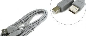
Required cables and adapters (depending on connection method):
You also need an adapter for audio streaming from a computer to a TV - in order to control the volume from the television remote control, and not on the computer speakers. These adapters from Jack Stereo to RCA are connected to the output on the computer sound card (where speakers or headphones are usually connected) and can look like this:
Standardization
In many European Union countries, S-Video cable is less common due to the dominance of SCART connectors found on most existing televisions. The player can output S-Video via SCART, but the TV's SCART sockets are not necessarily connected to receive it, and only a monochrome image will be shown on the display. In this case, it is enough to change the SCART adapter cable.
Game consoles sold in PAL territories do not typically include an S-Video VGA cable output. Early consoles came with RF adapters and composite video (on PAL TVs) on classic RCA video connectors.
In the US and some other countries, NTSC S-Video is available on some video equipment, including most televisions and game consoles. The main exceptions are VHS and beta video recorders.
Connectors
If the number of connectors that a SCART adapter can have directly depends on its class, then even a standard satellite tuner has three of them:
- the first is intended for connection to a TV;
- the second is used to connect players;
- the third provides the ability to connect a decoder for various “closed” programs.
For the latter, it is especially convenient to use a SCART connector. An adapter from any other cable of this type can also be used - through them the encoded signal will enter the decoder, and then return back in an “open” form. The situation is exactly the same with cable decoders of various paid programs, the use of which can now be carried out using a single cable of this interface.
Physical connectors
The four-pin mini-DIN connector is the most common of several types of S-Video cinch cable connectors. The same mini-DIN connector is used on Apple Desktop Bus for Macintosh computers, and the two cable types can be interchanged. Other connector options include the seven-pin locking "redundant" connectors used on many professional S-VHS machines, and the two Y and C BNC connectors often used for S-Video patch panels (HDMI cables). Early Y/C video monitors often used RCA connectors that switched between Y/C and composite video input. Although the connectors are different, the Y/C signals for all types are compatible.
Mini-DIN cables are prone to damage when used in kinked areas. This may result in loss of color or other damage to the signal. A bent pin can be forced back into its original shape, but this may cause the pin to break.
These connectors are typically manufactured to be compatible with an S-video RCA cable and include additional features such as component video using an adapter.
Part 2. Connection and setup
Connection procedure and precautions
Never connect the TV while the computer is on! Disconnect the plugs of both the TV and the computer from the power outlets, otherwise you can burn the inputs on both the TV and the video card!
Connection order:
1. Turn off the TV, disconnect the plug from the outlet.
2.Unplug the antenna plug from the TV - since a TV connected to a collective antenna can have a potential difference of more than 100 volts with an ungrounded computer, as well as all wires belonging to audio/video equipment (VCRs, DVD players, stereos, etc.). 3.Turn off the computer, unplug the plug from the outlet. 4.Connect the TV and computer with the necessary video and audio cables using the appropriate adapters. 5.Turn on the computer and wait for the operating system to load. 6.Turn on the TV. Setting up the connection for different video cards looks different, and the names of tabs, groups of controls and buttons may also look different - all this does not allow us to give universal instructions for setting up absolutely all video cards, but in each case approximately the same procedures are performed. It should also be noted that the quality of the video signal will not deteriorate when connecting the TV to a computer.
For computers with Windows XP operating system
In this example, a desktop computer with the Windows XP Service Pack 2 operating system installed and a GeForce FX 5600 video card via an S-Video cable was used to connect to the TV.
Connection order:
1. Turn off the TV, unplug the power plug, and disconnect the antenna cable.
2. Turn off the computer, unplug the plug from the outlet. 3.Connect the TV and computer with the necessary video and audio cables using the appropriate adapters (in this example, via an S-Video cable). 4.Turn on the computer and wait for the operating system to load. 5.Turn on the TV, select the INPUT S-Video function in the TV settings. 1) Right-click on an empty area of the Desktop, go to Display Properties, select the tab | Settings
2) Click on the monitor with the number 2, right-click and select Enable:
Note:
If the Extend my Windows desktop onto this monitor operating mode is selected, then it becomes possible to move the window with the player onto the television screen with the mouse.
Double clicking on the image or a key combination will expand the player to the entire television screen. Double-clicking on the image or pressing the keys again will return the image to windowed mode. After finishing watching the program, you need to return the player window from the television screen to the monitor. 3) At the bottom of the settings window, click the Advanced button. In the window that appears, select the Default Monitor and NVIDIA GeForce FX 5600 Properties section, and in the nView Display Settings section select the Clone mode as shown below:
4) Next, in the Full Screen Video section for Full Secondary Device, select Secondary Display
After clicking the Apply button, you may need to restart your computer. In the following example, a laptop computer with the Windows XP Service Pack 2 operating system installed and an ATI RADEON 7500 video card via an S-Video cable was used to connect to a TV.
The connection procedure and basic settings are practically the same as those discussed for NVIDIA video cards (see below):
The Extend my Windows desktop onto this monitor mode is installed as desired. In the simplest case, you don’t have to make additional settings using the Advanced button.
For computers running Windows Vista
In this example, a Dell Inspiron I1520 laptop computer with Windows Vista Home Premium installed via an S-Video cable was used to connect to the TV.
Connection order:
-Turn off the TV, unplug the plug from the socket, unplug the antenna cable.
-Turn off the computer and unplug it from the socket. -Connect the TV and computer with the necessary video and audio cables using the appropriate adapters (in this example, via an S-Video cable). -Turn on the computer and wait for the operating system to load. -Turn on the TV, select the INPUT S-Video function in the TV settings. After turning on the computer, the resolution may immediately change (for example, 720*480), and a screen like this should appear:
You need to set the mode to Duplicate my desktop on all displays (mirrored), then click OK. Then right-click on an empty area of the Desktop, select Personalize -> Display Settings
Next, you need to right-click on the monitor under number 2 and select Attached from the menu that appears. Then click on the Advanced Settings button and select the Intel® Graphics Media Accelerator Driver for Mobile tab (see below):
Next, click on the Graphics Properties button, to confirm the change in settings in the User Account Control window that appears, select Continue and in the window that appears, select the Intel ® Dual Display Clone mode and for the Secondary Device select the Television (or Monitor) mode:
After clicking OK, you need to return to the Display Settings window again, click on the monitor with the number 2.
There are 2 viewing modes on TV:
a) the image is displayed on both the monitor and the TV simultaneously - in this case, you must uncheck the Extend the desktop onto this monitor item; b) the image from the monitor is “dragged” by the mouse beyond it onto the TV (as on the 2nd screen), making it possible to work on the computer with other applications and at the same time watch programs from the Vidachok.TV service on the TV - in this case, you must check the box Extend the desktop onto this monitor item – see below:
Note:
If the Extend the desktop onto this monitor operating mode is selected, then it becomes possible to move the window with the player onto the television screen with the mouse.
Double clicking on the image or a key combination will expand the player to the entire television screen. Double-clicking on the image or pressing the keys again will return the image to windowed mode. After finishing watching the program, you need to return the player window from the television screen to the monitor. In some cases, after making changes, you may need to restart the computer. 1) There is a TV Tool program (you can download it from the website https://tvtool.info/), which does not require any video card settings. It is quite simple to operate - when you start this program, you can simply click - and the picture from the video card will go through one of the video outputs and the corresponding cable to the TV. TV Tool works with any video cards based on nVidia chips, with the exception of GeForce4 MX. Video cards with chipsets from other manufacturers (ATI, SiS, Trident, etc) are not supported by TV Tool. Supported by operating systems: Windows 98, Me, Windows 2000, XP, Vista. After installing TV Tool, you need to make some settings - select the signal type, resolution and picture size, as shown below:
The TV-format setting depends on the television standard (format) adopted in your region - see the table:
Next, on the Adjust tab, you need to set the video output port (S-Video or “tulip”) - depending on what type of connection is used - see below:
Now, every time before outputting an image from a computer to a TV, the procedure will be as follows: - launch the TV Tool; — go to www.vidachok.tv and select a program to watch; — open the transmission to full screen on the monitor; - press on the keyboard - the picture should disappear on the monitor, and appear on the TV.
2) Sometimes after connecting the computer to the TV, the image becomes quite cloudy, with interference, and synchronization may also “break down”. This can happen for the following reasons: a) The cable resistance is below 75 Ohms (the cable resistance is written directly on it); b) Unstable operation of the power supplies on the computer or TV may occur. When connecting additional equipment, this leads to the operation of such unstable power supplies at the limit of their capabilities, which affects the quality of the picture; c) When you connect a grounded computer to the TV, you get two grounding points (one at the far end of the television cable, the other in the computer), as a result of which image interference is possible. You can get rid of this by disconnecting the antenna cable from the TV during operation. d) Poor quality cable and poor cable connection. 3) When buying a flat-screen TV, it is best to take a laptop, connection cables with adapters to the store, and try connecting it to the selected TV there in the store. Thus, you can immediately find out whether it is possible to connect such a TV to a computer at all, and also see the quality of the signal output to the TV.
7-pin connector
Non-standard 7-pin mini-DIN connectors (called "7P") are used in some computing devices (PCs and Macs). The 7-pin connector is compatible with the standard 4-pin S-Video connector. Three additional sockets can be used to supply composite (CVBS) and RGB or YPbPr video signals. The use of S-Video cable wiring varies among manufacturers. In some implementations, the remaining pin must be grounded to enable the composite output or disable the S-Video output. Some Dell laptops have a 7-pin digital audio output.
Contact distribution
The SCART connector is equipped with several groups of contacts that provide transmission of certain signals from the TV and back:
- 5 lines for transmitting and receiving audio;
- 9 lines for receiving and transmitting video signals;
- 2 lines for selecting modes;
- 3 lines for digital data transmission.
All lines are marked in different colors, which greatly facilitates the process of installation and connection of various devices. SCART is still very popular among a large number of users.
The scart implemented the ability to transmit stereo audio signals, which was later transferred to other more modern types of HDMI connectors. Due to the design features of the connector, data transfer is possible when controlled remotely. You can also connect unmodulated signals:
- composite;
- component;
- S-Video.
Component video signals include RGB and YPbPr. And S-Video includes 2 lines. The function of switching video signal reception modes and waking the TV from sleep mode upon command from an external device was added to the connector only in the late 80s. In the same years, SCART was supplemented with 2 video signal transmission lines S-Video.
Although the interface is large and inconvenient, many manufacturers still install it in their equipment with the expectation of using it to connect to old TV receivers. And in order to connect other types of devices to it, for example, a video camera, you will need a special adapter.
gslider srcs=»https://instanko.ru/wp-content/uploads/kak-podklyuchit-resiver-k-televizoru-cherez-skart4.jpg,https://instanko.ru/wp-content/uploads/perehodnik- vga-scart.jpg,https://instanko.ru/wp-content/uploads/404935.jpg,https://instanko.ru/wp-content/uploads/kak-podklyuchit-resiver-k-televizoru-cherez- skart3.jpg,https://instanko.ru/wp-content/uploads/kak-podklyuchit-resiver-k-televizoru-cherez-skart2.jpg"]
9-pin video input/video output
9-pin connectors are used in graphics systems that have the ability to input video as well as output it via an S-Video Scart cable. Here too, there is no standardization between manufacturers as to which pin does what, and there are two known variations of the connector used. As you can see from the diagram above, although S-Video cable signals are available on the appropriate pins, none of the connector options accept an unmodified 4-pin S-Video connector, although they can be configured by removing the plug key.
Photo built diagram
This circuit version of the tabs is built to be an example of how the circuit can be built. If you've built yourself that, you can use components that work very well inside the case connector and build the circuit so that you CNA put the connector cases in place. If you plan to have more than a few centimeters between connectors, it's a good idea to use shielded signal cable (75 ohm coaxial cables are best; shielded audio cable works well over distances of up to several meters).