When operating commutator electric motors, there is often a need to regulate the speed of the device. It is important not to reduce the overall performance of the engine so that the work does not go down the drain. Let us consider in detail the features of independent regulation.
Regulator according to the diagram
Power units of this type are actively used in household electrical appliances, tools: washing machines, grinders, vacuum cleaners, drills, quadcopters, etc. This is due to the high efficiency of devices that demonstrate a high number of revolutions and high torque (also starting). These technical characteristics are more than enough to ensure the operation of equipment and tools at the required level.
The motors themselves operate from both direct and alternating current networks, from ordinary household networks. To control the rotor speed of such an engine, it is necessary to use special regulators. At the same time, losses in capacity will be minimal.
Common parameters
The operating principle and general design of such power units are known to most, because when creating or modernizing a design one cannot do without knowledge in this category. The motor consists of the following key elements:
- rotor;
- stator;
- switching unit of brush-collector type.
When power is applied to the rotor and stator, magnetic fields are formed on each of them, which interact with each other. This in turn causes rotation in the rotor.
Power is supplied to this component using graphite brushes that fit tightly to the commutator lamellas. To change the direction of rotor rotation, you need to change the position of the voltage phases on one of two elements: the stator or the rotor.
The windings of these devices can receive power from sources, or be connected to each other in parallel. It is on the basis of this feature that power units are classified into parallel and sequential. The method of exciting the copper windings depends on this.
If we talk about sequential type commutator motors, then they are most often used in household electrical appliances. This is due to the fact that it is precisely this kind of excitation that makes it possible to obtain the most overload-resistant motor.
More details:
The module is a small board with all the necessary elements for wiring and built on a TDA1085c . A prerequisite for connection is the presence of a tachometer (tachogenerator), which allows for feedback from the electric motor to the microcircuit. When the engine is loaded, the speed begins to drop, which is detected by the tachometer, which commands the microcircuit to increase the voltage and vice versa, when the load weakens, the voltage to the engine drops. Thus, this design allows you to maintain constant power of the commutator motor when the rotor speed changes.
This module fits well with the electric motor from an automatic washing machine . In combination of two devices, you can easily make it yourself: Wood lathe, Milling machine, Honey extractor, Lawn mower, Potter's wheel, Wood splitter, Emery, Drilling machine, Feed cutter and other devices where rotation of mechanisms is necessary.
There is an option for capacitor power supply:
The cost of this board is 57.00 BYN .
Connection
To connect the commutator motor to the control board, you need to understand the pinout of the wires. A standard commutator motor has 3 groups of contacts: tachometer, brushes and stator winding. Rarely, there may also be a 4th group of thermal protection contacts (the wires are usually white).
Tach sensor : located at the rear of the engine with wires coming out (smaller in cross-section than the others). The wires can be probed with a multimeter and may have a slight resistance.
Brushes : wires connect with each other and the engine commutator.
Winding : wires have 2 or 3 terminals (with a middle point). The wires communicate with each other.
When connecting the commutator motor to a 220 Volt network:
We short-circuit one end of the brush and winding wires (or put a jumper in the terminal block), connect the other end of the wires to a 220V network. The direction of rotation of the motor will depend on which of the winding wires will be connected to the 220V network. If you need to change the direction of movement of the motor, place a jumper on another pair of “winding-brush” wires.
When connecting a brushed motor to the speed controller board:
We connect the wires that connected the engine to the 220V network to the “ M” . to the Taho . to the “LN” . Polarity doesn't matter.
The kit includes a switch (terminal SA ). If a switch is not needed, install a jumper.
Settings
The board provides 3 types of settings:
— adjusting the smoothness of the speed increase;
— setting the speed control range.
For operational reliability and correct setup, it is recommended to perform the setup in the following sequence:
1) Setting the smoothness of the set of revolutions is carried out by trimming resistor R1 , which is responsible for the smoothness of the set of revolutions of the commutator motor.
2) The tachometer is adjusted using trimming resistor R3, which allows you to eliminate jerking and jerking in engine operation when adjusting the rotation speed.
3) The speed adjustment range is adjusted using trimming resistor R2 . The setting allows you to limit or increase the minimum speed of the commutator motor, even with the potentiometer turned down to the minimum.
Reverse connection
To connect the reverse switch, you need to remove the jumper in the motor (winding and brushes). The wires in the switch are separated by three pairs of wires, one of which has tinned ends. The pair with tinned ends is connected to terminal M. The remaining two pairs are connected to the winding and brushes. Which pair will be connected to the winding or brushes does not matter. The polarity of the connection does not matter.
A pair of wires for connecting to the engine tach sensor is green or black.
The reverse switch is not included in the standard package of the board and must be purchased separately.
Scheme for connecting the reverse to the board:
Board is customized and tested before sale!
Specifications
Regulators are standard
As for these components, they are implemented in many ways. The first and simplest circuit is a thyristor circuit. This technology is used in household appliances: washing machines, drills, screwdrivers, vacuum cleaners, etc. They can easily be connected to alternating current networks, including for household purposes.
Standard scheme
The operation of this circuit is quite simple: in all sections of the network currents, the capacitor receives current using a resistor. Charging is carried out to the opening level of the dinistor, which is connected to the regulating electrodes of the sismistor. After this, the latter opens and current passes through it to the CD loads.
The circuit makes it possible to productively regulate the recharging time of the capacitor in the control circuit, as well as determining the average voltage power supplied to the motor.
Let's streamline all the steps of this scheme. Here they are:
- supplying current to the capacitor from a 220 volt power source;
- the voltage for breakdown of the dinistor is also supplied, but through a variable resistor;
- direct breakdown;
- opening of the triac. The component works directly with load indicators;
- the higher the voltage, the more often the triac opens.
This technology provides simple, but at the same time effective regulation of speed intensity. But, at the same time, the use of a standard scheme does not provide feedback, which should also be taken into account when implementing it. Based on this, you also need to know that when the load indicators change, the engine speed will need to be adjusted in parallel.
Triac circuit
This mechanism has many common parameters with a dimmer used to regulate the brightness level of incandescent lamps. There is also no feedback. Implement mono current reverse, but with the use of auxiliary electronics. This is done in order to smoothly maintain power at the specified levels, avoiding overheating and overloads.
Rheostat circuit
It refers to modified schemes, but despite this, its implementation is also simple. With the help, it is possible to stabilize the speed, as well as dissipate the huge amount of generated heat. The adjustment is carried out using a radiator, which must be prepared in advance. It is also necessary to ensure effective heat removal, which leads to energy losses and, as a consequence, efficiency. In order to prevent these shortcomings, it is recommended to use active cooling on an ongoing basis.
Rheostat circuit example
The resulting limiter regulator is distinguished by its efficiency when changing the engine speed. Power transistors, which “take away” a certain portion of the voltage, will also help achieve performance. This is due to the fact that the amount of current from the 220V network reaches the motor in a smaller volume, due to this, the power unit does not encounter heavy loads.
Integral
Stabilization also applies to modified schemes. Here, the control process is based on an integral action timer. Its main task is to control the load levels on the electric motor. Transistors also find their use here. The peculiarity is determined by the microcontroller that is part of the system, which at the same time has high output voltage parameters.
In situations where there is a load of 0.1 ampere, all currents flow directly to the board, bypassing the transistors. To ensure efficient operation of the regulator, it is necessary that there is a voltage of 12V at the gate. Therefore, for smooth operation, the electrical circuit and voltage level in the power source must correspond to this range. The resource of the regulator allows you to install the component in powerful modifications for precise and quick regulation of their operation.
Integrated circuit
Operating principle
Speaking about household and industrial devices, such as a 220V electric drive for a honey extractor, a 220V engine heater with a pump and other systems, it is worth remembering that at the moment of starting these and other electric drives, the winding of the power unit is deformed and simultaneously heated. The voltage receiver is a controller that rectifies the current through the diode. Next, the energy is directed to a system of capacitors that act as a filter. The power output is the current passed through the PWM controller and released into the rotor windings, tuning the motor to operate at a specific speed.
Adjusting the speed of the electric drive of a honey extractor or other production equipment is carried out in several ways by changing the parameters of the power supply supplied to the motor windings:
- decrease or increase in voltage indicator;
- change the current frequency;
- current adjustment.
The most commonly used types of speed control:
- The autotransformer system is implemented in the form of a moving contact that comes into contact with the winding. This changes the speed of rotation of the rotor. This type of control is used in 220V engine heaters with a pump and other systems where a clear alternating voltage sinusoid and high resistance to possible overload are needed;
- triac, or thyristor, speed control changes the level of the supplied voltage by activating a thyristor pair assembled in opposite directions, or turning them on simultaneously with the triac. This circuit is used not only in industrial asynchronous electric motors, but also in small household appliances, such as an electric drive for a honey extractor, a dimmer, various switches, etc.;
- the introduction of resistance is carried out using one or several types of converters - variable resistors, separating devices, etc. This technique has proven itself positively in single-phase motor configurations, where it is used to control slip. Changing the difference between the armature speed and the magnitude of the stator magnetic field effectively helps reduce the speed. To implement resistance tuning, high-power electric motors are used, since less voltage can be applied to them. In this case, the standard ratio will be up to two times smaller.
Each type of control has its own advantages. It is necessary to make a choice for a specific motor (single-phase, three-phase, etc.), as well as according to the consumer’s parameters.
Creating a regulator yourself
Factory regulators are presented in a wide range, both on the Internet and in regular stores. But, if you have no desire to purchase a ready-made component and want to assemble it yourself, this can actually be done. For the task to be successful, it is necessary to follow the design algorithm and have all the necessary components available.
We will need:
- wiring;
- ready-made diagram;
- capacitor circuits;
- thyristor;
- resistor;
- soldering iron
Based on the layout diagram, the power and rotation regulator will be responsible for controlling the first half-cycle. A homemade stabilizer has the following operating algorithm (example of our model):
- the device connected to a standard 220V power supply receives current to the capacitor;
- the component fires immediately after receiving a charge;
- load transfer to resistors and bottom cables;
- connecting the positive capacitor contact to the thyristor electrode;
- supplying one voltage charge at a sufficient level;
- discovery of a second semiconductor;
- the capacitor supplies the thyristor with a load, which in turn passes it through itself;
- the capacitor is discharged;
- half-cycle repetition;
If the power of a DC or AC motor is high, the regulator ensures economical operation of the device. There is enough power and resource to use the device in your household. But, when you need to regulate speed without loss of power and larger and more productive units, then you should still pay attention to factory modifications. Despite the fact that this option will be more expensive, it will ensure 100% performance and reliability.
Now let's look at other, non-standard, but quite common methods of adjustment and stabilization.
Method 2
It uses a TDA 1085 type chip with a standard board. You can, if you wish, create your own by “upgrading” and changing inappropriate elements. For example, you can use a double-sided printed circuit board. Capacitor and resistor parts can be used for surface mounting. It is recommended to separate low- and high-voltage circuits from each other. And the “ground” must be distributed taking into account the parameters of the microcircuit.
An example of an assembled board
The result is a compact, double-sided board that provides precise control.
Main parts for assembly
Before assembling the regulator, you need to stock up on the necessary elements and tools. This:
- Sufficient set of wiring.
- Diagram (taken from technical literature or the Internet).
- Soldering iron for work.
- Capacitors, thyristor, resistors, etc.
To your attention! High-quality regulation is achieved by including variable resistors in the circuits, providing a smooth (or stepwise) change in the number of revolutions.
Frequency control
To solve this problem, frequency converters (drivers, inverters) are used, which are connected to the device. They provide rectification of the voltage coming from the source. The units inside generate voltage and frequencies at the required levels. Next, these parameters are supplied to the electric motor.
Stabilization of a 12V commutator motor All characteristics necessary for regulating operation are calculated by the frequency operator itself, focusing on internal algorithms that are installed by the manufacturer.
Among the advantages of this method it is worth highlighting:
- quickly achieve smooth adjustment of the speed of the electric motor;
- the ability to change the speeds and directions of rotation of the motors;
- the required parameters are independently supported;
- economic benefits.
Among the weaknesses, it is worth highlighting the mandatory presence of a converter, which must be purchased separately. But, in fairness, we note that the price of frequency devices is low and they can easily fit into the budget of any home, household, or enterprise.
Types of engines
The speed control with power maintenance is an invention that will breathe new life into an electrical appliance, and it will work like a newly purchased product . But it is worth remembering that engines come in different formats and each has its own maximum performance.
The engines have different characteristics. This means that this or that technique operates at different speeds of the shaft that triggers the mechanism. The motor can be :
Mostly three-phase electric motors are found in factories or large factories. At home, single-phase and two-phase are used. This electricity is enough to operate household appliances.
Changing the number of poles
Decreasing or increasing the number of pole pairs is another effective way to make adjustments. This option is especially relevant for multi-speed motor models with complex rotor windings. These elements are divided into specific groups and alternate during the work process. This is done through switching, connecting in a serial or parallel manner.
The advantages of this adjustment option include:
- high efficiency of the power unit;
- demanding mechanical output characteristics.
The cost of implementation is one of the highest when compared with other technologies. The weight and dimensions of the finished installation are also rather large, which requires free space for installation. The speed monitoring itself is carried out in steps of 1500 – 3000 rpm.
How to make it yourself?
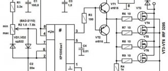
There are various options for adjustment schemes. Let us present one of them in more detail.
Here is how it works:
Initially, this device was developed to adjust the commutator motor in electric vehicles. We were talking about one where the supply voltage is 24 V, but this design is also applicable to other engines.
The weak point of the circuit, which was identified during testing of its operation, is its poor suitability at very high current values. This is due to some slowdown in the operation of the transistor elements of the circuit.
It is recommended that the current be no more than 70 A. There is no current or temperature protection in this circuit, so it is recommended to build in an ammeter and monitor the current visually. The switching frequency will be 5 kHz, it is determined by capacitor C2 with a capacity of 20 nf.
At the same time, it is recommended to select the value of R1 in such a way as to correctly configure the operation of the regulator. From the output of the microcircuit, the control pulse goes to a push-pull amplifier using transistors KT815 and KT816, and then goes to the transistors.
The printed circuit board has a size of 50 by 50 mm and is made of single-sided fiberglass:
This diagram additionally shows 2 45 ohm resistors. This is done for the possible connection of a regular computer fan to cool the device. When using an electric motor as a load, it is necessary to block the circuit with a blocking (damper) diode, which in its characteristics corresponds to twice the load current and twice the supply voltage.
Operating the device in the absence of such a diode may lead to failure due to possible overheating. In this case, the diode will need to be placed on the heat sink. To do this, you can use a metal plate that has an area of 30 cm2.
Regulating switches work in such a way that the power losses on them are quite small. In the original design, a standard computer fan was used. To connect it, a limiting resistance of 100 Ohms and a supply voltage of 24 V were used.
The assembled device looks like this:
When manufacturing a power unit (in the lower figure), the wires must be connected in such a way that there is a minimum of bending of those conductors through which large currents pass. We see that the manufacture of such a device requires certain professional knowledge and skills. Perhaps in some cases it makes sense to use a purchased device.
Carrying out regulation in AC motors
Devices operating on alternating voltage also support speed control. Let us briefly consider the main methods of such control, characteristic of AC modifications with phase-wound rotors.
Using voltage
For this purpose, autotransformers of the LATR type are used, which change the voltage on the motor windings. This is how the shaft speed is controlled.
The method is also suitable for variations with squirrel cage rotors. The operator has the opportunity to carry out control within the range from minimum to nominal engine parameters.
Regulator
Definition of resistance
The variable resistance of the rheostat (or several such phenomena) is realized directly in the rotor circuit. It affects the rotor field and current indicators, which makes it possible to change the slip values and the exact number of revolutions of the electric motor. There is a pattern: the lower the current level, the higher the motor slip rate and the lower the speed.
Advantages:
- wide range of speed control of electrical equipment;
- restrained output characteristics of the machine.
The disadvantages include:
- decrease in engine productivity;
- general decrease in the operating parameters of the mechanism.
Dual power application
Motors with dual power supplied through valve fittings are used here. The main emphasis is on changing slip performance. When regulating the operation of large specialized machines, the component supplies and regulates the amount of EMF (electromotive force) to the rotor from separately selected voltage sources.
Controller Specifications
In general, such homemade devices meet the following technical parameters:
- supported voltage range = 110 - 240 Volts;
- loads of 2.5 kW are possible;
- use of operating power within 300 W;
- It is possible to regulate the speed in the range from 9 to 99%.
If, after reading all the information, the question arises of how to make a speed controller for your engine, diagrams and tips from specialists will certainly help you figure out this essentially simple matter. Yes, and there are several ways: mounted mounting, on the surface of a printed circuit board or circuit board.
Conclusion
When voltage is applied to asynchronous motor models, the rotor jerks. This phenomenon negatively affects the operation of both the unit itself and its drive. That is why the adjustment is carried out according to the principle of a smooth start. It is provided by the following factors:
- start via LATR;
- acceleration and operation of the motor by switching windings according to triangle/star circuits;
- the use of protective devices, for example, a frequency converter.
It is important when regulating the speed not to lose power. Using the methods described above will allow you to determine rotations without reducing productivity. A wide selection of factory models, but you can also implement the part yourself.
Connection methods
Before you begin integrating the speed controller, you must read the manual. The type and mechanism of operation of the existing model is indicated there. Without this information, you can make a mistake and cause a module or engine breakdown. As a rule, the connection diagram for the speed controller does not differ much between the varieties of the latter, so the user manual will present a drawing of a typical electrical circuit.
After studying the integration diagram, you need to understand how the pinout method is used. With its help, the number of pins for full control of the existing type of electric motor is determined. Next, a comparison is made between the output contacts of the electric motor and the color codes of the regulator connectors. It is necessary to select devices so that there are no unconnected outputs. If any contact remains unused, they can be short-circuited so that the operation of the motor is not disrupted. When all the symbols match, you can start connecting and connecting to the power supply.