Third Eye (Part 1)
Part 1 Part 2 Part 3
In Eastern beliefs, it is believed that the “third eye” is a kind of energy center, a part of the brain with the help of which a person gains the possibility of supersensible perception, the ability to see with his eyes closed and to look unhindered into any corner of the universe.
Sites in the city are a potential “minefield”, in which underground utilities and other objects that can be damaged during excavation work carried out by construction and utility services act as mines: power and telephone cables, sewer and gas pipes, etc. d. Damage to underground communications causes losses amounting to millions of rubles: they have to be repaired, the deadlines for completing basic work and commissioning of objects are violated. In such accidents, people are injured and even killed. Even if workers have at their disposal a plan for the location of underground communications, they cannot completely rely on it, since it is not known whether all newly laid communications have been included in it. Before starting excavation work, workers must know for sure that there are no communications in the ground that are not indicated on the plan. It should be noted that there is no universal location method that allows identifying any underground objects - each method has a specific scope and a number of limitations. Therefore, construction and utility companies widely use various equipment to search for underground communications.
DIY route finder
When carrying out any construction and installation work, it is necessary to have precise knowledge of the location of underground pipeline routes and cable lines. In order not to resort to digging up the ground to find them, which is expensive and can damage communications, it is better to use a route finder. You can buy it in a store, or you can assemble the locator yourself .
Generator circuit
This device is assembled from two main blocks: a generator and a receiver. The device allows you to accurately determine the center line of communications with great accuracy up to 10 cm, laid at a meter depth, and determines the approximate location of the damage, its range of 3-4 km. The figure below shows a diagram of the locator . The device is powered by a 24 V battery; the capacity of the KBS-0.5 battery is capable of providing 100 hours of uninterrupted operation of the device. Basically, the entire do-it-yourself locator circuit is not complicated; the master oscillator with a modulator is assembled on transistor T1, P14. When switch Bk1 is open, transistor T1 with circuit L1C3 in the collector circuit and with elements R1C2 in the base circuit create a type of LC generator with an operating frequency of 1 kHz. Even partial inclusion of the circuit in the collector circuit will allow you to connect large loads to the collector T1 of the transistor.
By turning on capacitor C1 with the help of Vk1, the time constant of the main circuit increases sharply and the generator becomes a super generator operating in the VHF range, this is the only way the modulation frequency can reach 2-3 Hz. The cascade on transistor T2, P14 serves as a buffer between the generator and the push-pull output stage; it is assembled on transistors T3, T4 - P201. R2 resistance forms the desired current mode T2 for transistor, and R3 lowers the supply voltage, which is supplied to the first 2 low-power transistors in circuits that protect against overload according to the maximum permissible parameter. R4, R5 create an initial mode for the output stage transistors so that they operate without distorting the output power. The sectional winding of the output transformer is designed to match the generator output with loads of 1-2 ohms, 50 and 200 ohms. Generator output power is 5-8 W.
Receiver circuit
To assemble a locator with your own hands, you need to know what its second part consists of - a receiver with a magnetic antenna, it is shown in the figure below.
The antenna circuit L1C1 must be tuned to the frequency of the generator, its audio frequency voltage passes through resistance R1 to the input of the amplifier, it consists of 4 transistors P14. The first 2 transistors, together with the T-shaped bridge, create a selective amplifier, and the use of bridge conductivity makes it possible not to use transition capacitances, resulting in a stable circuit. R1 ensures normal operating conditions for the amplifier, and two cascades on transistors T3 and T4 create the required gain; high-impedance phones like TON-2 are also used.
Details and design of the device
The locator device is mounted on a getinaks board, it is inserted into its body on a slide, its size is 150 * 100 mm. Two toggle switches, power and output terminals are installed on the front panel. The coil of the device L1 consists of 500+500 turns of PEL 0.1 wire. Transformer T1 is wound on a ferrite ring with a diameter of 8 mm, and T2 is wound on a special steel core. The antenna coil is wound on a regular ferrite rod measuring 140*8 mm. As you can see, it is quite possible to assemble a locator with your own hands , but if you don’t want to do this, you can buy a ready-made model in an online store.
Operating principle of cable locators
In addition to monitoring the condition of the cable route, the devices in question can also establish the exact location of the cable (not only in the ground, but also in the walls of buildings), establish its depth, and detect various underground objects. Their use is especially effective when laying new cable networks, since it allows optimizing the volume and labor intensity of the required excavation work.
The cable line router implements the well-known phenomenon of electromagnetic induction, in which any metal conductor carrying current forms an electromagnetic field around itself. In the case of a power cable, this is the operating voltage current of the line; for a steel pipeline, this is the eddy pickup current. It is these currents that are captured by the device.
The devices under consideration can operate according to active and passive circuits. The first is more effective, and therefore is mainly used in cases where several underground communications are densely located in the area under study.
The difficulty of the search lies in the fact that the saturation of the soil with such conductors is very high, therefore, sources from other lines, serviceable or not currently subject to control, can be “woven” into the final signal recorded by the locator. Therefore, a distinctive feature and advantage of modern active-type locators is the possibility of a relatively simple and, at the same time, precise adjustment of readings related to a strictly defined cable line. This possibility is determined by the presence in the locator circuit of two independent units - a signal generator and a signal receiver.
The generator provides an electrical signal of a certain frequency to the conductor. Not only can it not coincide with the frequency of 50 Hz usually used for alternating current networks, but it must also be as different as possible from this value. This minimizes the likelihood of random interference or pickup (especially for underground pipelines, the pickup current of which is, generally speaking, unknown).
How do locators work?
Electromagnetic locators determine the position of pipes and cables based on the magnetic field existing around the communication being studied. Isolation of communications and soils of various types surrounding communications do not change the appearance of the field. The strongest signal is received when the device is located directly above the communication.
Passive and active modes. If an alternating electric current flows through a communication, it creates a magnetic field and the device can find the communication while operating in passive mode. However, the accuracy of this method is relatively low; with its help, it is difficult to determine the depth of a communication more than 1–2 m and find it if several other communications are located next to it.
If no electric current flows through the communication, then in order for the locator to identify this cable or pipeline, a current must be created in it using a generator. This mode of operation of the device is called active. This method is more accurate than the passive method and allows you to identify an object at greater depths and distances.
When any end or section of the pipe or cable being sought is accessible, for example through a manhole, the generator is connected to the service by means of an alligator clip or induction clamp and a signal is induced therein. Using a generator is very convenient when identifying one of the many nearby communications. The generator is connected to the communication, the inductive current is induced only to this object, and it is easily tracked by a locator at a distance of 1 km or more from the generator connection point. Initially, this method was used to search for defects in electrical and telephone cables. Electric current is supplied to the cable, the operator with the receiver walks along the route, determining its location. At the site of a break, short circuit or other defect, the power of the received signal changes sharply.
When there is no access to the desired communication, using a generator capable of creating a volumetric inductive electric field, a current of a certain frequency (that is, an inductive magnetic field) is remotely injected into the communication, which is picked up by the receiver.
The optimal frequency for effective location depends on the type of soil, the type of pipe or cable, and many other factors. Therefore, locating devices from the world's leading manufacturers can operate at different frequencies, from several hertz to 200 kHz. Moreover, the choice of operating frequency can be either automatic or set manually. Many locator models have only two or three most commonly used operating frequencies: 50 Hz for locating live power cables and 100 Hz for tracing steel pipes under cathodic protection. More advanced foreign models offer a wider range of operating frequencies - from 10 to 35 kHz. This significantly increases the resolution and sensitivity of the device in conditions of an abundance of various communications and strong electromagnetic “noise”.
Receiver. The principle of operation of the receiver is quite simple. It tunes to the frequency of the signal from the communication and, based on changes in signal strength, determines the location of the object. The operating range (distance from the generator to the receiver) for different types of locators ranges from 0.5 m to 20 km with a location accuracy of 10 to 30 cm; the maximum depth at which the device provides route determination is usually up to 10 m. Instrument readings depend on the class of the device, the diameter of the route, the signal power of the generator, the type of soil, and the presence of interference. In particular, large-diameter pipes and cables have a large surface area in contact with the ground and, as a result, signal leakage to the ground. At the same signal strength, its attenuation due to leakage to the ground in large pipes occurs over a shorter distance than in small-diameter communications. There are modifications of devices designed to search for extended objects - pipes, cables, and modifications for detecting small objects, such as manhole covers or pipeline valves.
The devices provide digital processing and optical indication of the received signal. Models with a graphic display usually show digital values of electromagnetic field parameters or, at best, a bar graph of signal strength. It is more convenient to perceive the signal strength “by ear” through headphones, by the tone of the receiver’s sound. When the operator walks along the area in which the communication is located, the receiver generates an audio signal, the tone of the signal becomes higher as the device approaches the communication and begins to gradually decrease as it moves away from it. By marking the places on the soil surface where the signal tone was the highest, the operator marks the underground communication route. An experienced operator can confidently distinguish different types of pipelines and cables by the sound of the device. A number of domestic models of locator finders only have an acoustic indication function. But it is more convenient to work with devices that, along with the audio signal, display traces on the screen, as well as the depth of the communications. Such devices are especially convenient in the case of studying intersecting communications. Mastering such devices does not require special knowledge and skills.
One of the features of the magnetic reconnaissance method is that the strongest signals come from the end points of the object being studied, because the magnetic field lines converge at them. Therefore, a vertically oriented object (even a small steel barrel) is often easier to detect than a horizontally oriented water pipe a hundred meters long. The same effect occurs in the places of connecting joints of the same water pipeline, consisting of separate sections: on the screen of a magnetic prospecting device, a picture appears from a chain of signals of maximum strength, corresponding to the locations of the joints of individual sections of the pipe, from this picture you can determine the route and depth of the object by connecting between are separate points.
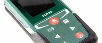
Progress in the design of route finders. Modern models of locating equipment have improved protection against electromagnetic interference, making the search for communications much easier. The most complex models of route finders are connected to a laptop computer and, using special software, allow you to obtain complete information about the spatial position of underground and underwater communications in the surveyed area, and also have the ability to work together with GPS/GLONASS receivers for reference to absolute geographic coordinates. Data can be entered into electronic maps and into an electronic project of a construction project.
Currently, the electrochemical method of protecting metal pipes from corrosion is widespread. Therefore, some locators have a CPS function - “cathodic protection search”, which makes finding such communications easy and quick.
Manhole finders. Utilities, and especially organizations that maintain various cables, often need to find manholes hidden under snow and soil. For this purpose, electromagnetic metal detectors of a specific design are used. The device has a sensor - an inductive coil, in which the generator creates a high-frequency electromagnetic field. When the sensor approaches a metal hatch, the frequency of the field changes, which is reflected in a change in the tone of the sound signal in the headphones. More advanced devices, in addition to headphones, are equipped with an LCD display on which search results are presented visually.
Insulation resistance measurement
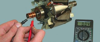
Measuring the cable insulation resistance is the next step in finding cable damage. A megohmmeter or cable bridge can be used as a device for measuring insulation resistance. A modern cable bridge can not only replace a megger, but also significantly expand the possibilities of detecting cable damage through the use of bridge measurement techniques.
The cable bridge allows you not only to evaluate the quality of the cable insulation, but also to calculate the distance to the leakage point, estimate the cable capacitance, measure the loop resistance and ohmic asymmetry. It is the search for leaks, along with the search for cable breaks, that are the most common damage to the cable line. Thus, a time domain reflectometer and a cable bridge, combined into a single device, significantly increase the chances of finding the location of cable damage. RI-10M2 is a lightweight, portable and easy-to-use device that combines bridge measurement techniques and a pulsed discontinuity locator. The combination of price and functionality makes this cable fault detection device popular among consumers.
Locator components
The electromagnetic locator consists of a lightweight portable heterodyne receiver, which provides high noise immunity and sensitivity, making it possible to work in conditions of strong external interference, with a weak signal level, in areas saturated with communications. The receiver has control buttons and a display on which the results of the locator search are displayed. The receiver can be powered by batteries or an electrical cable.
The communications being sought may be energized or de-energized. To search for de-energized communications, a compact generator (transmitter) is used - a source of electromagnetic pulses of a certain frequency. The generator can be connected to the pipe or cable being tested using terminals, or pulses can be transmitted into the communication in a non-contact manner.
To receive signals, antennas are used, one or more, of various designs and spatial orientations, which can also be rotated.
If you need to determine the position of a non-metallic pipe through which a liquid flows, and the pipe does not have a satellite wire, you can use special locators that are equipped with floating probe sensors, which, moving in the pipe along with the liquid, allow you to determine the location of the pipe. Similarly, video head locators with a miniature transmitter are used to locate damage and blockages in pipes. To determine the location of damage to a cable or pipe (and, accordingly, the location of electric current and water leaks), use contact probes buried in the ground, included with the device.
Classification of testers
All modern cable locators are divided into many types and varieties, based on such characteristics as the class of the device, the type of cable on which it can make measurements, the type of results obtained and the method of displaying them.
By class
All cable locators are divided into 2 main classes:
- Semi-professional – having functionality suitable for novice system administrators and home DIYers. They allow you to carry out the simplest tests necessary for beginners on various cables and communication lines.
- Professional – devices that have an expanded range of functions and allow for various tests and measurements on different communications (telephone and local) networks.
Interesting. In addition to functionality, devices of these classes differ in cost: professional, more reliable and high-quality models, cost on average 1.5-2 times higher than their semi-professional counterparts.
By cable type
Depending on what physical communication channels locators can work with, they are divided into 2 main types:
- Working with fiber optic communication channels and local networks;
- Designed for testing communication lines with copper conductors, such as twisted pair, coaxial or telephone wire.
The second type of device, due to the fairly high use of twisted pair in modern computer networks and telephone lines, is currently the most common and in demand. Devices for fiber optic lines, due to their high cost, are purchased exclusively by specialists involved in the installation of such communications.
Based on the results
According to this criterion, all locators are divided into devices that allow troubleshooting, measurement of various characteristics, and certification of data transmission lines.
Electromagnetic locators (locators)
These are devices for determining the location and damage of underground conductive utilities (cables of electric and telephone lines, metal and polymer, pipelines for liquids and gases reinforced with metal cord or equipped with a signal wire, ducts, etc.) in plan and depth. Today, route finders are popular equipment for maintaining and monitoring the condition of underground communications; they are used to identify illegal tappings, places where pipes are blocked, and detect cables and other fittings underground. Depending on their narrow purpose, devices may have “telling names”: cable detectors, leak detectors, sunroof detectors, flaw detectors, etc.
Causes and types of damage to cable lines
There are many factors that negatively affect the integrity of power cables, the most common of which include the following:
- Ground movement can be caused by a failure of water supply, sewer or heating networks, as well as seasonal phenomena, for example, spring thawing.
- Exceeding the permissible operating standards for cable lines, which can lead to thermal overload of the line caused by an increase in current load.
- Formation of a high level of electric current in the cable line from a transit short circuit.
- Mechanical damage during excavation work without taking into account the passage of underground communications and the depth of the route.
- Errors when laying cable lines. As an example, we can cite violations of the technology for connecting cores with cable couplings.
- Manufacturing defects.
Note that when cable routes are laid open, some of the above causes of damage are extremely rare. In particular, the likelihood of the influence of soil movement and mechanical impacts due to excavation work is reduced. In addition, damage zones of open cable lines, in most cases, can be detected by visual inspection, without the use of special methods.
Having dealt with the reasons, let’s move on to the types of damage, since this directly determines the method by which the emergency section of the cable line will be localized.
Most often, repair teams have to deal with the following types of faults:
- A defect caused by a complete or partial break of a cable line. Most often, the cause of the accident is excavation work without determining the passage of cable routes. Somewhat less frequently, the cause of this damage can be a short circuit in the couplings.
- In power cables (more than 1 kV), breakdown of one of the conductors to ground (single-phase short circuit) is often encountered. Leakage current, as a rule, is caused by a decrease in the quality of insulation during operation of the cable line.
- Interphase damage, as well as types of metal short circuits, can occur in any lines; the cause of damage is the same as in the previous paragraph.
- Routine cable testing, which involves high voltage levels, shows low insulation reliability and leads to breakdown. Under certain circumstances, such a line can continue to operate, but due to its low level of reliability, an accident can occur at any time.
Advantages and disadvantages of locators
Simple, portable electromagnetic locators are relatively inexpensive, readily available, can be rented, and are relatively easy to learn to use—and can be used effectively even by inexperienced operators.
The main disadvantage of the electromagnetic location method is that it cannot be used to trace communications that do not conduct electric current: plastic, concrete and ceramic pipes.
This problem is solved by using other devices - ground penetrating radars, which we will talk about in the next article.
Part 1 Part 2 Part 3
Acoustic method of damage detection
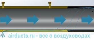
The simplest device for the acoustic method is a high voltage source (testing machine), with a high voltage capacitor . The damaged core is connected to the capacitor through a spark gap .
The installation charges the capacitor. As soon as the voltage on it exceeds the breakdown voltage of the spark gap, it breaks down to the damaged core. An acoustic wave rushes into the cable, reaching the point of damage. As a result, it produces a strong sound effect (clicking).
Connection diagram for acoustic fault detection method
Modern output installations have contactors powered by a control unit. With its help, both the output voltage and the pulse repetition rate are set.
To listen to acoustic signals at the site of damage, piezoelectric sensors installed on the ground or the same locators are used. Moving along the route and listening to the signal, they look for the place of its maximum. It corresponds to the location of the damage.
After the search is completed, the cable line is excavated in an area 5–10 m from the suspected damage. Then the acoustic method is used to verify its presence directly on the cable. After this, the location of the damage is cut out, and the cable line is tested with increased voltage on both sides. If the test is successful, they begin to repair it. If unsuccessful, look for the location of the next damage.
Tester with signal generator Mastech MS6813T (13-1221)
0)window.scrollBy(0,-100);">
By submitting data, you agree to the privacy policy.
0)window.scrollBy(0,-100);">
By submitting data, you agree to the privacy policy.
Ways to receive orders
Pickup in Moscow - more details.
— There is no minimum order amount. — Moscow, Novokhokhlovskaya str., 91, building 10. -c 10.00
until
20.00
on working days in the Russian Federation.
Payment:
- cash upon receipt. — by bank card through the terminal. — bank transfer according to the issued invoice (payment is credited within 24 hours)
Delivery in Moscow - more details.
— The minimum order amount is 1000 rubles. — 300 rubles within the Moscow Ring Road. — from 10.00 to 18.00 on working days in the Russian Federation.
Payment:
- cash upon receipt. — bank transfer according to the issued invoice (payment is credited within 24 hours)
Delivery in the Moscow region - more details.
— The minimum order amount is 1000 rubles. — 500 rubles up to 10 km. from MKAD. — 40 rubles per 1 km. from the Moscow Ring Road + 300 rubles within the Moscow Ring Road, depending on the order amount. — from 10.00 to 18.00 on working days in the Russian Federation.
Payment:
- cash upon receipt. — bank transfer according to the issued invoice (payment is credited within 24 hours)
Delivery to cities of the Moscow region by Courier Service - more details.
— The minimum order amount is 1000 rubles. — Delivery to the Courier Service terminal in Moscow — Free. — All courier services are paid by the buyer. — Prepayment of the order by bank transfer against the account, payment for Courier Service services upon receipt.
Sending to Russian cities by Courier Service - more details.
— The minimum order amount is 1000 rubles. — Delivery to the Courier Service terminal in Moscow — Free. — All courier services are paid by the buyer. — Prepayment of the order by bank transfer against the account, payment for Courier Service services upon receipt.
Sending to cities of the Russian Federation by Transport Company - more details.
— The minimum order amount is 1000 rubles. — 300 rubles delivery to the Transport Company terminal in Moscow. — All services of the Transport Company are paid by the buyer. — Prepayment of the order by bank transfer against the account, payment for the services of the Transport Company upon receipt.
Ways to receive orders
— There is no minimum order amount. — Moscow, Novokhokhlovskaya str., 91, building 10. — from 10.00 to 20.00 on working days in the Russian Federation. — the order is paid upon receipt.
— The minimum order amount is 1000 rubles. — 300 rubles within the Moscow Ring Road. — from 10.00 to 18.00 on working days in the Russian Federation. — the order is paid upon receipt.
- Delivery in the Moscow region - more details.
— The minimum order amount is 1000 rubles. — 500 rubles up to 5 km. from MKAD. — 40 rubles per 1 km. from the Moscow Ring Road + 300 rubles within the Moscow Ring Road, depending on the order amount. — from 10.00 to 18.00 on working days in the Russian Federation. — the order is paid upon receipt.
- Delivery to cities of the Moscow region by Courier Service - more details.
— The minimum order amount is 1000 rubles. — Delivery to the Courier Service terminal in Moscow — Free. — All courier services are paid by the buyer. — Prepayment of the order, payment for Courier Service upon receipt.
- Sending to Russian cities by Courier Service - more details.
Features and Specification
The Mastech ms6812 cable tester-router is sold in a small cardboard box, on the back of which the main technical characteristics of the device are written.
Thus, a locator consists of a signal transmitter and receiver, with the help of which it is possible to carry out the following actions:
- track the cable route;
- search for wire;
- test for wire breaks;
- detect the location of a wiring break;
- determine the polarity, integrity and condition of telephone lines when connecting the transmitter to telephone sockets;
- send a single-tone signal over the wires.
Technical characteristics of the Matech hidden wiring detector:
- generated frequency - 1.5 kHz;
- frequency range - from 100 Hz to 300 kHz;
- device weight - 417 g.
Mastech runs on a Krona battery. The package includes: receiver, transmitter, set of batteries, soft case and instruction manual presented in English.