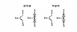
Transistor tester / ESR meter / generator
Multifunctional device for testing transistors, diodes, thyristors...
More details
DIY ESR meter . There is a wide range of equipment breakdowns, the cause of which is precisely the electrolytic capacitor. The main factor in the malfunction of electrolytic capacitors is “drying out,” familiar to all radio amateurs, which occurs due to poor sealing of the housing. In this case, its capacitive or, in other words, reactance increases as a result of a decrease in its nominal capacity.
In addition, during operation, electrochemical reactions take place in it, which corrode the connection points between the leads and the plates. The contact deteriorates, eventually forming “contact resistance”, sometimes reaching several tens of ohms. This is exactly the same if a resistor is connected in series to a working capacitor, and moreover, this resistor is placed inside it. This resistance is also called “equivalent series resistance” or ESR.
The existence of series resistance negatively affects the operation of electronic devices by distorting the operation of capacitors in the circuit. Increased ESR (about 3...5 Ohms) has an extremely strong impact on the performance of switching power supplies, leading to the burning of expensive microcircuits and transistors.
The table below shows the average ESR values (in milliohms) for new capacitors of various capacities depending on the voltage for which they are designed.
It is no secret that reactance decreases with increasing frequency. For example, at a frequency of 100 kHz and a capacitance of 10 μF, the capacitive component will be no more than 0.2 Ohm. When measuring the drop in alternating voltage having a frequency of 100 kHz and higher, we can assume that with an error in the region of 10...20%, the result of the measurement will be the active resistance of the capacitor. Therefore, it is not at all difficult to assemble an ESR meter for capacitors with your own hands .
Calculations using electrical engineering formulas
The simplest RC circuit consists of a resistor and a capacitor connected in parallel.
After performing mathematical transformations (not given here), the properties of the circuit are determined, from which it follows that if a charged capacitor is connected to a resistor, it will discharge as shown in the graph.
The product RC is called the time constant of the circuit. When R is in ohms and C is in farads, the product RC equals seconds. For a capacitance of 1 μF and a resistance of 1 kOhm, the time constant is 1 ms, if the capacitor was charged to a voltage of 1 V, when a resistor is connected, the current in the circuit will be 1 mA. When charging, the voltage across the capacitor will reach Vo in time t ≥ RC. In practice, the following rule applies: in a time of 5 RC, the capacitor will be charged or discharged by 99%. At other values, the voltage will change exponentially. At 2.2 RC it will be 90%, at 3 RC it will be 95%. This information is sufficient to calculate the capacity using simple devices.
Measuring circuit
To determine the capacitance of an unknown capacitor, you should include it in a circuit consisting of a resistor and a power source. The input voltage is selected slightly lower than the rated voltage of the capacitor; if it is unknown, 10–12 volts will be sufficient. You also need a stopwatch. To eliminate the influence of the internal resistance of the power source on the circuit parameters, a switch must be installed at the input.
The resistance is selected experimentally, more for the convenience of timing, in most cases within five to ten kiloohms. The voltage across the capacitor is monitored with a voltmeter. Time is counted from the moment the power is turned on - when charging and turning off, if the discharge is controlled. Having known resistance and time values, the capacitance is calculated using the formula t = RC.
It is more convenient to count the discharge time of the capacitor and mark the values at 90% or 95% of the initial voltage; in this case, the calculation is carried out using the formulas 2.2t = 2.2RC and 3t = 3RC. In this way, you can find out the capacitance of electrolytic capacitors with an accuracy determined by the measurement errors of time, voltage and resistance. Using it for ceramic and other small capacitances, using a 50 Hz transformer and calculating capacitance, gives an unpredictable error.
DIY capacitor capacitance meter
Simple circuits for measuring esr oxide capacitors
Do-it-yourself capacitor capacitance meter - below is a diagram and description of how, without much effort, you can independently make a device for testing capacitor capacitance. Such a device can be very useful when purchasing containers on the radio-electronic market. With its help, low-quality or defective electrical charge storage element can be easily identified. The schematic diagram of this ESR, as most electronics engineers usually call it, is not anything complicated and even a novice radio amateur can assemble such a device.
Moreover, the capacitance meter does not require a long time and large financial costs for its assembly; it literally takes two to three hours to manufacture a probe of equivalent series resistance. It is also not necessary to run to a radio store - any radio amateur will probably have unused parts suitable for this design. All you need to replicate this circuit is a multimeter of almost any model, but preferably one that is digital and has a dozen parts. There is no need to make any alterations or upgrades to the digital tester; all that needs to be done with it is to solder the pins of the parts to the required pads on its board.
Schematic diagram of the ESR device:
List of elements required to assemble the meter:
One of the main components of the device is a transformer, which should have a turns ratio of 11:1. Ferrite ring core M2000NM1-36 K10x6x3, which must first be wrapped with insulating material. Then wind the primary winding on it, arranging the turns according to the principle - turn to turn, while filling the entire circle. The secondary winding must also be made with a uniform distribution around the entire perimeter. The approximate number of turns in the primary winding for the K10x6x3 ring will be 60-90 turns, and the secondary should be eleven times smaller.
You can use almost any silicon diode D1 with a reverse voltage of at least 40v; if you don’t really need super accuracy in measurements, then the KA220 is quite suitable. To more accurately determine the capacitance, you will have to install a diode with a small voltage drop in the direct connection version - Schottky. The protective suppressor diode D2 must be designed for reverse voltage from 28v to 38v. Low-power silicon pnp transistor: for example KT361 or its analogue.
Measure the ESR value in the voltage range of 20v. When connecting the connector of an external meter, the ESR attachment to the multimeter immediately switches to the capacitance testing operating mode. In this case, a reading of about 35v will be visually displayed on the device in the test range of 200v and 1000v (this depends on the use of a suppressor diode). In the case of testing capacitance at 20 volts, the reading will be displayed as “out of measurement limits”. When the connector of the external meter is disconnected, the EPS attachment instantly switches to operating mode as an ordinary multimeter.
Conclusion
The principle of operation of the device is that to start operating the device, you need to plug in the adapter into the network, and the ESR meter turns on; when the ESR is turned off, the multimeter automatically switches to the mode of performing standard functions. To calibrate the device, you need to select a constant resistor so that it matches the scale. For clarity, the picture is below:
When the probes are shorted, 0.00-0.01 will be displayed on the multimeter scale; this reading means the instrument’s error in the measurement range up to 1 ohm.
ATTACHMENT FOR MULTIMETER ESR METER
I not only learned from others that such a meter is necessary for a radio amateur, but also felt it myself when I undertook to repair an old amplifier - here you need to reliably check each electrolyte on the board and find the one that has become unusable or replace them 100%. Selected check. And I almost bought an advertised device called “ESR – mikro” via the Internet. What stopped me was the fact that they praised him too much - “over the edge.” In general, I decided to take independent action. Since I didn’t want to try microcontroller devices, I chose the simplest, if not primitive, circuit, but with a very good (thorough) description. I delved into the information and, having some inclination towards drawing, began to design my own version of the printed circuit board. To fit into the case of a thick felt-tip pen. It didn’t work out - not all the details were included in the planned scope. I thought better of it, drew a signet in the image and likeness of the author’s, etched it and assembled it. I managed to assemble it. Everything turned out very thoughtfully and neatly.
But the probe didn’t want to work, no matter how much I fought with it. But I didn’t want to retreat. For a better understanding of the diagram, I redrew it in my own way. And so “dear” (in two weeks of ordeal), it became more understandable visually.
Add-ons
How to make a knife with your own hands at home
Composite transistor T1 (KT829, circuit Fig. 3) can be replaced with two transistors of lower power according to a standard circuit, and for a 1.4 V power supply you can assemble a simple stabilizer on one transistor. These diagrams are shown in Fig. 5 and 6 respectively.
Silicon diodes VD1-VD3 are used here as a zener diode, approximately 1.5 V. Unlike a zener diode, the diodes should be turned on in the forward direction.
If desired, you can supplement the device with a module for quickly checking the functionality and pinout of transistors. It can be used to test any bipolar transistors, as well as low- and medium-power field-effect transistors. Moreover, bipolar transistors can be checked without unsoldering them from the circuit. The diagram is shown in Fig. 7.
Depending on the LEDs used, you need to select the resistance R5 according to the optimal brightness of their glow (or install an additional quenching resistor in the 9 V power circuit, but in general this circuit works with a supply voltage starting from 2 V). When nothing is connected to terminals “E”, “B”, “K”, both LEDs blink (the blinking frequency can be changed by the values of capacitors C1 and C2). When a working transistor is connected to the terminals, one of the LEDs will go out (depending on its conductivity type pnp / npn). If the transistor is faulty, both LEDs will blink (internal open) or both will go out (short).
The device, using all of the above modules, was assembled in a housing with dimensions of 140x110x40 mm and allows you to test almost all the main types of radio components most often used in practice, with sufficient accuracy for radio amateurs. It has been used for several years and does not cause any complaints.
↑ Design
YX-360TR
multimeter was chosen as an “experimental test” , fortunately it is at hand everywhere, and the measuring head is suitable.
We remove all unnecessary insides, remove the nameplate, and cut off the protruding parts on the front panel with a scalpel. The seat for the range switch is cut out with a jigsaw, and the resulting opening is closed with plexiglass (polystyrene) of suitable thickness.
The newly manufactured board must exactly follow the contours of the factory board in order to ensure fastening to existing clamps.
Homemade C-meter
DIY VGA adapter
Without taking into account various exotic solutions, such as a ballistic galvanometer and bridge circuits with a resistance store, a novice radio amateur can make a simple device or an attachment for a multimeter. The widely used 555 series chip is quite suitable for these purposes.
This is a real-time timer with a built-in digital comparator, in this case used as a generator.
The frequency of rectangular pulses is set by selecting resistors R1–R8 and capacitors C1, C2 using switch SA1 and is equal to: 25 kHz, 2.5 kHz, 250 Hz, 25Hz - corresponding to switch positions 1, 2, 3 and 4–8. The capacitor Cx is charged at a pulse repetition rate through the diode VD1, to a fixed voltage. The discharge occurs during a pause through resistances R10, R12–R15. At this time, a pulse is formed with a duration depending on the capacitance Cx (larger capacitance - longer pulse). After passing through the integrating circuit R11 C3, a voltage appears at the output corresponding to the pulse length and proportional to the value of the capacitance Cx. A multimeter (X 1) is connected here to measure voltage at a limit of 200 mV. The positions of switch SA1 (starting from the first) correspond to the limits: 20 pF, 200 pF, 2 nF, 20 nF, 0.2 µF, 2 µF, 20 µF, 200 µF.
Adjustment of the structure must be done with a device that will be used in the future. Capacitors for adjustment must be selected with a capacity equal to the measurement subranges and as accurately as possible, the error will depend on this. Selected capacitors are connected one by one to X1. First of all, the subranges of 20 pF–20 nF are adjusted; for this, the corresponding trimming resistors R1, R3, R5, R7 are used to achieve the corresponding multimeter readings; you may have to slightly change the values of the series-connected resistances. On other subranges (0.2 µF–200 µF) calibration is carried out with resistors R12–R15.
The wires connecting the resistors to the switch should be as short as possible, and if the design allows, they should be placed on its terminals. It is advisable to use multi-turn variables; it is better to use constant ones, but this is not always possible. It is necessary to thoroughly wash the printed circuit board from flux and other dirt, otherwise parasitic capacitances and resistance between conductors can lead to complete inoperability of the product.
When choosing a power source, it should be taken into account that the amplitude of the pulses directly depends on its stability. Integrated stabilizers of the 78xx series are quite applicable here. The circuit consumes a current of no more than 20–30 milliamps and a filter capacitor with a capacity of 47–100 microfarads will be sufficient. The measurement error, if all conditions are met, can be about 5%; in the first and last subranges, due to the influence of the capacitance of the structure itself and the output resistance of the timer, it increases to 20%. This must be taken into account when working at extreme limits.
Advanced LCR meter assembly kit
For quite some time now I have been using a homemade capacitance and ESR meter for capacitors, assembled according to a circuit from the author of GO from the ProRadio forum. Along the way, I also use another, no less popular FCL meter from the cqham website. Today we are reviewing a device that has the above stated accuracy, and also actually combines both of the above devices. Attention, many photos, little text, may be critical for users with expensive traffic. It’s probably worth starting with the fact that this device is sold in its entirety, i.e. already assembled. But in this case, the designer was chosen purposefully, since at a minimum it allows you to save a little money, and at maximum, just enjoy the assembly. And probably the second is more important. In general, I have long wanted to change the previous model of the C-ESR meter. In principle, it works, but after at least one repair it began to behave inappropriately when measuring ESR. And since I work a lot with switching power supplies (although this is also true for conventional ones), this parameter is even more important to me than just capacity. But in this case, we are not dealing with just a C-ESR meter, but with a device that measures ESR + LCR, and the full list of measured values is even longer, in addition, good accuracy is also claimed.
Inductance 0.01 uH - 2000H (10 uH) Capacitance 200pF - 200 mF (10pF) Resolution 0.01pF Resistance 2000 mOhm - 20 MOhm (1.5 Ohm) Resolution 0.1 mOhm Accuracy 0.3 - 0.5% Test signal frequency 100 Hz , 1 kHz, 7.831 kHz Test voltage 200 mV Automatic calibration function Output impedance 40 Ohm
The device can measure - Q - Quality factor D - Loss factor Θ - Phase angle Rp - Equivalent parallel resistance ESR - Equivalent series resistance Xp - Equivalent parallel capacitance Xs - Equivalent series capacitance Cp - Parallel capacitance Cs - Series capacitance Lp - Parallel inductance Ls - Series inductance
In this case, the measurement is carried out using the bridge method using a four-wire connection to the component.
In my opinion, the closest competitor is E7-22, but it has less stated measurement accuracy (0.5-0.8%), a test frequency of only 120 Hz and 1 kHz and a test voltage of 0.5 Volts versus 0.3% , 120 Hz - 1 kHz - 7.8 kHz, 0.2 Volts for the monitor.
This device is sold in several configuration options; almost the most complete version is used in the review. Prices from the seller's page. 1. Only the device itself without a housing - $21.43 2. Device + one type of probes - $25.97 3. Device + a second type of probes - $26.75 4. Device + two types of probes - $31.29 5. Housing for the device. — $9.70
Everything was packed in a bunch of small bags.
Since when delivering through an intermediary the weight of the parcel is usually taken into account, I decided to weigh it additionally, without cables it came out to 333 grams, with cables it was noticeably more, 595 grams. In general, it is quite possible to buy without cables, especially if you have something to make them yourself from, since the difference in the price of the set alone is about 10 dollars, not counting the weight.
By the way, I’ll start with cables. Packed in separate bags, it even just feels like a decent weight.
The first set is essentially ordinary “crocodiles”, but larger in size and made of plastic. But in reality, not everything is so simple, the jaws are connected to different wires (connectors) to implement the correct four-wire connection. The cable is moderately flexible, the rigidity is rather added by the fact that there are four cables, and they are shielded. The probes are connected to the device itself using regular BNC connectors; the screen is connected only on the side of the BNC connector.
There are no complaints about the quality, the only thing I didn’t really like was the lack of color markings near the connectors, since the crocodiles themselves have them. As a result, to connect, you have to look at each time which one you connect where. The solution is to make a mark with electrical tape near the connectors.
But the second set is much more interesting; it allows you to work with small components, since it is a tweezers. The photo shows that the central cores of the wires are connected not at the ends of the tweezers, but at some distance, i.e. This option is slightly worse than the previous one, but implementing a system like the “crocodiles” is more difficult here. There is no color coding. For ease of use, the tweezers have a guide that protects the jaws from moving relative to each other. I don’t know how long they will last, but so far it’s quite convenient to use, although there is a note - you need to squeeze closer to the jaws themselves; if you squeeze the tweezers near the middle of the body, the jaws may not come together completely.
Just a few words about what a four-wire connection or Kelvin connection is.
With the usual measurement of resistance (by the way, not only resistance), such a parasitic thing as the wires to the probes can have a rather strong influence. I think many people know that it’s rare that a multimeter will show 0 with the probes closed and the lower limit of measurement. The indicator usually displays a certain value of about 0.05-0.5 Ohm, this is parasitic resistance. Sometimes it can be compensated by turning on the relative measurements function (Rel), but this is not always convenient and is not always correct.
The principle of measuring resistance is quite simple. We connect the component to a current source and measure the voltage on the component. But since we have wire resistance, we end up with a sum consisting of the real resistance of the component and the resistance of the wire. If the resistance is large, then usually this does not play a special role, but if we are talking about values of 1-10 ohms or less, then the problem comes out in full force. To solve this problem, the circuits through which current flows through the component and the circuits directly measuring are separated.
In real life it looks something like what is shown in the diagram.
In addition, a similar method is used, for example, in power supplies. For example, a photo from my review of a powerful converter. Here you can also separate the power circuit and the feedback circuit, then the voltage drop on the wires will not affect the voltage across the load. You've probably also seen something similar in computer power supplies using a 3.3 Volt circuit (orange wires). only there a three-wire circuit is used (the same additional thin wire to the power connector)
Power supply 12 Volt 1 Ampere, looks good. However, I tried connecting it just to a load, it works fine. But because of the plug with flat pins it is inconvenient to use, I will replace it with something else, fortunately the voltage is standard. In reality, the device can be powered by a voltage of 9-15 Volts. It’s a pity that you can’t choose a configuration without a power supply; I think many radio amateurs will have such a power supply at home.
The main part of the kit was split into three separate packages.
One of them has the most common 2004 display (20 characters, 4 lines) with backlight.
The device board was carefully wrapped in “air” film.
This is exactly the case when in the photo in the store the board seems smaller than it actually is. Real dimensions are 100x138mm.
The front part of the board is occupied by space for probe connectors.
The middle part is the measuring unit, switches, operational amplifiers. Apparently this unit was supposed to be shielded, but the shield itself is not included in the kit.
At the top are the “brains” and nutrition.
In the first versions of the device, linear power stabilizers were used, in this version they are replaced with pulse ones. Also visible is the connector for connecting the power supply and the switch. Replacing stabilizers with pulse ones can significantly help when powered by batteries. For example, the aluminum case comes with a cassette for 3 18650 batteries.
Everything is controlled by a 12C5A60S2 microcontroller. It is based on the old 8051 core and has an eight-channel 10-bit ADC on board. In the first versions of the device it was in a DIP-40 package, in new versions it was replaced with an SMD version.
The board also has a connector for connecting to the programmer.
Several individual photos of installed components.
The bottom is empty, only the soldering points of the screen and the control points of the outputs of stabilizers and power converters are displayed here.
Well, the last bag, with radio components that will actually need to be installed on the board.
This includes the keyboard board, as well as all sorts of resistors, capacitors, connectors, etc. In general, the design is quite well thought out, small components are already soldered on the board, only larger ones need to be installed and soldered. Those. the element of “assault” is retained, but there is no masochism for beginner radio amateurs in terms of soldering small components, and it’s much more difficult to “mess up”. As a result, you can assemble the device quite quickly and get a positive impression from the process.
The components are divided into bags, but mostly several denominations in one bag.
All resistors included in the kit are precision grade. At the initial stage, just in case, I measured their real resistance. It helps in the assembly that there are few values, but at the same time they can be easily measured even with a cheap tester, since there are no resistors too close to each other in value. Above is what needs to be soldered, there are essentially only six ratings - 40 Ohm, 1, 2, 10, 16 and 100 kOhm.
At the top are the resistors from the signed package; they are not soldered onto the board, but are used to check and calibrate the device. At first I thought that they needed to be soldered into some critical places, which is why I measured the resistance. But then it turned out that they were “superfluous”, and the number (16 pieces) of installed resistors coincided with the number that were in the first package.
The kit includes capacitors with ratings of 3.3, 10, 22, 47 nF, 0.1, 0.2 and 0.47 µF. In the photo below I have labeled the capacitors as they are labeled on the board.
In addition, connectors, a pair of electrolytic capacitors, a relay and a tweeter are additionally installed.
While I was waiting for my parcel, I searched the Internet for more information about the device. It turned out that there is not only a diagram, but also different versions of the printed circuit board, firmware, and in general quite a lot of people are working on this model. The diagram is, of course, quite conventional, but it gives a general understanding.
But along the way I remembered that about 8-9 years ago, in my city, a person was developing a similar device. If you look at the diagram, you can see a lot of similarities, and it was developed before the one being reviewed.
The seller's comment on the product page really cheered me up, sorry for the Google translation. In a simple form (well, very exaggerated) it means - I check all the boards, send them in excellent condition, so there is no need to send me your crafts, soldered with a hot nail on the knee with orthophosphorus instead of flux. Love your board and treat it like your beloved friend
It is worth noting that both the quality of the board and the soldering of components are 5 points. Everything is not only neatly soldered, but also thoroughly washed! In this case, all installation locations are marked and have both a position designation and an indication of the component rating. Honestly, 5 points.
Unboxing video and description of the kit. https://www.youtube.com/watch?v=dHWNAleJuYo
Let's move on to assembly. In general, when I opened all these packages and laid them out on the table, I really wanted to sit down and solder this structure right away, the only thing that stopped me was that it was decided to make some small instructions for assembly, if suddenly one of the beginners decided to do it. First of all, we pour resistors onto the table and find those that are most numerous, these are the values of 2 and 10 kOhm.
We install and solder them first. This will allow you to quickly remove most of the free spaces from the board and make it easier to find the remaining ones later.
We do the same with the remaining resistors, fortunately there are few of them left.
The situation is similar with capacitors; first we solder the 10nF capacitors (103), since there are the most of them.
Then the values are 0.1 and 0.22 uF (104 and 224).
It is extremely difficult to install relays and connectors incorrectly; the tweeter is marked + both on the board and on the tweeter itself (the long lead is a plus). A pair of electrolytic capacitors is also unlikely to cause problems, there is one of each value, the minus (short terminal) is indicated in white on the board.
The BNC connectors were soldered surprisingly well. In general, during the entire assembly I did not use flux; what was in the solder was enough.
The final touch is installing the racks. Here everyone already does it in their own way. In general, I don’t quite understand why there are 16 racks in the kit. 8 long ones are needed to install the keyboard board and indicator, let's say 4 short ones on the bottom or top, but why 8?
In the end, I did it my way, 8 long ones are on top of the board, and 4 short ones are on the bottom. This option makes it more convenient to temporarily use the board without a housing. In this case, the upper indicator posts stand with the screws up, and the short ones are screwed into them.
A couple of photos of the soldered board for control.
After assembly, we get a pretty beautiful printed circuit board, the main thing is not to mess anything up in the process
I molded the resistor leads using a small device, but it turned out that the distance between the leads was a little larger than necessary. In the end, I decided to raise the resistors a little above the board, but rather for beauty, at least I like it better.
After soldering, be sure to wash the board, since there was little flux, I made do with alcohol.
After assembly, I noticed that the board could be shortened a little from the base 138mm. Approximately up to 123-124mm if you leave the programming connector or up to 114mm if you cut it out too. In this case, the probe connectors are connected with wires into specially designed holes. Perhaps it will be useful when “packing” into a small case.
There are only buttons on the keyboard board, and they accidentally gave not 8, but 9 buttons. One button stuck to another.
But they didn’t include one “comb” in the kit; I had to gut the “stash” a little, and at the same time I took out the mating parts. True, in my case there were only corner connectors, but there were many. In general, it is useful to have a set of such connectors on the farm, they often help out.
Solder the connectors to the keyboard board and indicator. By the way, the keyboard connection is fully implemented, i.e. Each button has its own processor output, rather than using resistors and an ADC, as is sometimes the case.
That's all, the kit is completely ready.
When assembled, the layout resembles a multimeter, with an indicator on top, buttons below, and connectors even below.
As you can understand from what I wrote above, this is the second version of the device, essentially modified. But I like the case version of the previous version better and I plan to make just such a case version. True, such a case costs about 9-10 dollars, and if you buy it with a keyboard board and front panel, then even more. By the way, I already had a review of such a case, where I assembled an regulated power supply in it.
My version is designed for installation in an aluminum case.
And according to the idea it should look like in this photo. But let’s just say that design is more individual; I came across various options on the Internet.
After assembly, I was left with test resistors, a button and some fasteners. Well, and a power supply with probes, of course.
Now we move on to a description of the capabilities of the device and the specifics of its operation. When turned on, there is a welcome message, then the basic operating screen. By the way, everything worked right away, there are no trimming elements in the device at all, assemble it, turn it on, use it.
The device can operate in four main modes: 1. Automatic selection. Here the device itself determines what to measure. The choice is made according to the prevailing value. Those. if the component has a predominant capacitive component, it will switch to the capacitance measurement mode, if inductive, then to the inductance measurement mode. Sometimes it can be wrong, especially if the component has several distinct components, for example some resistors can be defined as inductance. To help the automation, a manual selection was added - 2. Capacitance measurement 3. Inductance 4. Resistance.
The indicator also displays the frequency of the test signal and the measurement limit. The measurement limits are somewhat “non-standard” and number as many as 16 pieces - 1.5, 4.5, 13, 40, 120, 360 Ohms. 1, 3, 9, 10, 30, 90, 100, 300, 900 kOhm and 2.7 MOhm.
By default, the device starts in automatic measurement mode at a frequency of 1 kHz.
A little about management. There are eight buttons under the indicator, it is labeled. M - Menu, from here the necessary calibrations and factory resets are performed. RNG - Range. In the menu, this button gives access to the calibration submenu. C - Fast automatic calibration. L — Switching the display mode (first photo). In the menu - memory X - Switching operating modes of the device. In menu mode, exit. R - Decrease value in calibration mode (X - increase) Q - relative measurement mode. Can be used to select two identical components. we connect the sample component, press the button, turn off the sample component and connect the selected ones. The percentage of discrepancy will be displayed on the screen (second photo). F - Frequency selection 100 Hz - 1 kHz - 7.8 kHz.
Device menu view.
The quick calibration mode by pressing button C has two options: 1. When measuring capacitance and inductance, it is performed with open probes. 2. When measuring resistance - with closed ones. In both options, the device self-calibrates three times for each frequency. 3, 4. Calibration in resistance mode, you can see the resistance of the probes before and after calibration.
In the mode of measuring small resistances, calibration is quite important, since the capabilities of the device allow you to even “see” the resistance of the capacitor terminals, not to mention the different wires.
Naturally, in this mode it is convenient to measure the resistance of low-resistance resistors, as well as such “non-standard” measurements as the resistance of button contacts, relays or connectors.
In terms of resistance measurement accuracy, the device can easily compete with my Unit 181.
When measuring inductance, the device also behaved quite well. The photo shows an inductance of 22 μH and three tests with different frequencies of inductance with a nominal value of 150 μH.
Now we can move on to the main thing, which is what I mainly need it for, measuring the parameters of capacitors.
At first I just poked different capacitors and saw what it showed, but one (or rather a pair) surprised me. I measured a pair of identical capacitors that were soldered from old (about 20 years old) Hungarian or Czechoslovak equipment. One showed 488 μF, and the second almost 600. Everything would be fine, but initially these are 470 μF 40 Volt capacitors. Moreover, they behave differently at a frequency of 7.8 kHz. Or rather, the difference in capacity is not proportional to each other.
Then I took another capacitor (like Matsushita), bought a long time ago, but still lying in the stash. The device was able to measure capacitance normally at frequencies of 100 Hz and 1 kHz, but at high frequencies the capacitance was displayed somewhat incorrectly. In general, at a frequency of 7.8 kHz the device sometimes behaves a little strangely, sometimes increasing the capacitance relative to the first two frequencies. Sometimes (when measuring capacitive capacitors) it falls into the —-OL—- mode or shows an excess of more than 20 mF.
By the way, the resolution of the device even allows you to see the difference in the connection location to the output. And using the example of one pin, you can see how the internal resistance changes. What I mean is that people sometimes ask me if it’s possible to connect a capacitor on the wires if it doesn’t fit into place. You can connect, but the performance will decrease slightly.
As you understand, it’s not interesting to simply measure capacitors, so I asked a friend for his E7-22. Along the way, I noticed that even the control of devices has a lot in common.
The first step was film capacitors. At the bottom is a precision 1% capacitor with a stated capacitance of 0.39025 µF.
1, 2. Polymer capacitor with a capacity of 100 μF 3, 4. But the E7-22 has problems with measuring large capacitances. The device under review easily measures a capacitance of 10,000 μF at a frequency of 1 kHz; the E7-22, even at 4700, was already producing an overload.
1, 2. Capxcon KF series with a capacity of 330 uF. 3, 4. A capacitor from the same company (allegedly), it just lay in a box for several years and became swollen.
And this is just for the sake of curiosity. A couple of capacitors from my old motherboard that ran 24/7 for about 10 years. 1. 2200uF 2. 1000uF
The capacity of the first capacitor has dropped noticeably, but the internal resistance is fine. More often it happens the other way around: the capacitance remains the same, but the internal resistance increases.
Video of the work process and tests. https://www.youtube.com/watch?v=CmLFt8OzF00
If you have any other test suggestions, then for now I have two devices on hand, I could experiment. It only occurred to me to check the scope of the test signal. Shown below is the test signal swing relative to ground. The top two are monitored at frequencies of 100 Hz and 7.8. kHz, lower - E7-22 at frequencies of 120 Hz and 1 kHz. The difference is about 2.5 times.
I wrote above that I plan to use a housing where the indicator is located not parallel to the surface, but perpendicular. But in the process it turned out that although the indicator was used and was relatively good, it was focused specifically on what would be viewed from the front or from the front-bottom.
At large angles, and even more so when viewed from above or from the side, the image disappears or begins to invert.
This is actually why I decided to finally try a display made using VATN technology. In general, I wanted OLED, as I already did, but it’s almost impossible to buy 2004, and as it turned out later, VATN is also rarely sold online. As a result, I had to go to our offline store and buy there. There were three models to choose from, with blue, green and white font, I liked the white one better, model - WH2004A-SLL-CTV, price about 15-16 dollars, link. Manufacturer: WINSTAR.
At first glance, the indicators differ little from each other, at least the size of the board is completely identical - 98x60 mm.
There is a slight difference at the bottom, but seemingly insignificant.
The new indicator is approximately 0.5mm thinner.
The general connection principle is almost the same, with the exception of a few nuances, which I will discuss below.
To begin with, the difference is that VATN displays need a negative voltage to adjust the contrast, so a voltage converter based on the well-known 7660, which I also reviewed, is mounted on the board. Nearby there is a place for a tuning resistor. The middle pin goes to the contrast adjustment contact, the other two go to + 5 and - 5 Volts, respectively.
At first I wanted to install a trimming resistor, giving full control to the indicator board, but then I decided not to bite out the extra contact of the connector and simply turned on the resistor so that one contact went to the standard contrast adjustment pin (number 3 on the common connector), and the second to the negative 5 output Volt. I adjusted the image, soldered out the tuning resistor, it turned out that I needed a constant resistor with a resistance of 2.6 kOhm, the closest one at hand was 2.49 kOhm, and I already soldered it “stationary”.
But that wasn't all. And now Attention, pin 15 of the connector for the usual indicators is the positive output of the backlight, here it is the negative voltage output and in no case should you simply change the indicator from one to another, in the end you will simply burn it out.
I did it a little differently, out of 16 contacts I soldered only 14. Pin 16 is the minus of the backlight, and the plus is connected to the input +5 Volts, so I just threw a jumper between the minus of the backlight and the common wire of the indicator board.
And here attention is the second time! Initially, I thought of simply leaving pin 16 in place, since a regular indicator has the backlight minus displayed there, reasoning that it makes no difference where it is connected to the common wire. And it would work normally if not for one BUT. On the device board, the indicator is powered by + 5 Volts, and the backlight by -5 Volts. Therefore, having connected the new indicator in this way, literally after 10-20 seconds I accidentally noticed that its backlight began to warm up wildly. Having connected with a tester, I found out that not 5, but 10 Volts (+5 and -5) were used for the backlight. Therefore, with this device it was necessary to connect the minus of the backlight to the common contact of the board.
Change the indicator and try. Well, what can I say, this is certainly not an OLED, but it is far from an ordinary LCD. Of the minuses, it is more oriented towards the fact that they will look at it in any way, but not from below, in this version it will become “blind” from the flash.
At the same time, I measured the current consumption with the old indicator and the new one. 1. old - 48 mA all together or 12 mA only indicator. 2. new - 153 mA or 120 mA indicator only.
Yes, for a battery-powered version, a regular LCD indicator is much more profitable.
If viewed from above, i.e. As I planned, visibility is good, but inactive pixels begin to appear. You can easily get rid of the latter, but then, when viewed directly, it shows dimly; I set it to something in between.
The viewing angles are, of course, head and shoulders above those of a conventional LCD; the image is readable even when looking almost parallel to the screen. But an interesting effect emerged (last photo). If you smoothly turn the screen away from you, then at some point (at about 30 degrees of rotation) the image fades, tries to invert, and with further rotation it almost sharply becomes normal again. Therefore, the display is perfect for vertical installation, but sometimes it can be annoying when installed horizontally.
This is the position in which I intended it to be used; I have no complaints here.
Next, I planned to “settle” it, for which I bought a Z1 case. At first glance everything is neat.
But the case is very large, actually one and a half times larger than required, but I would like something more compact. Case dimensions (external) - 188 width, 70 height and 197 depth. This is the last size and I would like to reduce it to 140-150, even if you take it and drink. Maybe someone knows suitable cases?
There is also a discussion on this device, but there is much more information on foreign sites. One of the users of the Pro-radio website even made a collection where he put all the information he found, firmware, boards, drawings, etc., for which a huge thank you to him!
For example, one of the foreign radio amateurs posted a method for calibrating the device. Not a bad Google translation, the original is here.
The calibration is quite extensive to describe, I'll catch up sometimes. ForenMenber Blueskull kindly translated chapter 6 from Chinese to English for me. How useful this is now I'll have to try, but my meter seems to be well calibrated, I'm a little shy.
First, I'll look at the included reference resistors. I have a more accurate ohmmeter (DMM PM 2534) (Under construction!)
6. LCR Meter Calibration There are 7 calibration menus that need to be calibrated, a total of 10 (15?) parameters, respectively M0 ~ M8 and "M3.", "M5.", "M6.", "M7." And "M8."
M0 - Zero offset at 100 Hz, LSB unit, default - 20. M1 - Zero offset at 1 kHz, LSB unit, default - 20. M2 - Zero offset at 7.8 kHz, LSB unit, default - 14. M3 - phase compensator for VI converter in 20 ohm range, unit 0.001rad, default is 0. M4 is phase compensator for VI converter in 1 kohm range, unit is 0.001rad, default is 0. M5 is phase compensator for VI converter in range 10 kOhm, unit 0.001rad, default - 0. M6 - phase compensator for VI converter in the range 100 kOhm, unit 0.001rad, default - 20. M7 - second stage phase compensation, unit 0.001rad, by default - 16. M8 - first stage PGA phase compensation, unit 0.001rad, default - 20.
"M3." - calibration of the lower arm for the VI converter at 20 Ohms, unit 1%, default - 0. "M4." - calibration of the lower arm for the VI converter at 1 kOhm, unit 1%, default - 0. "M5." - calibration of the lower arm for the VI converter at 10 kOhm, unit 1%, default - 0. "M6." - calibration of the lower arm for the VI converter at 100 kOhm, unit 1%, default - 0. "M7." - second PGA gain calibration, unit 1%, default - 0. "M8." - first PGA gain calibration, unit 1%, default 0.
In the LCD1602 version these parameters are named Z0, Z1, Z2, R1X, R2X, R3X, R4X, G1X, G2X, R1, R2, R3, R4, G1 and G2.
To restore factory settings, press the C key 5 times to restore the default settings, then press the L key to save.
Before calibration, you need to prepare several resistors:
To calibrate the VI converter, 20R, 1k, 10k, and 100k resistors are required.
To calibrate the PGA, 3.3k and 10k resistors are needed (translator's note: you also need 330R and 100R).
At 1KHz and 7.8KHz, connect 20R, 1k, 10k and 100k resistors when calibrating the corresponding ranges, the gain setting of the upper and lower arms should be identical for amplitude and phase calibration. Press M+R key to enter the control menu, if "1, 1" is displayed, then both hands are balanced and the gains are identical. If "0, 1" or "1, 0" is displayed, the signal amplitude is incorrect.
Offset calibration (M0, M1, M2)
Ensuring zero offset is the basis for measuring accuracy and hence it is recommended to take the first step in calibration. Using a given specification, the offset zero points are also identical for individual assemblies, so preset values can be used. If calibration is necessary, do the following (note: the translator added this sentence):
For M0 at 100 Hz:
1, Set f=100Hz, range=100k 2, Connect 1% 10R resistor as DUT 3, Read R value from menu 1
In the 10k (100 kHz) range, measuring a 10R resistor will result in a larger error, and this is normal. If the error is higher than 2%, you need to adjust M0 to bring it to 2%.
M1 and M2 can be calibrated using the same method at different frequencies (1 kHz and 7.8 kHz).
The buzzer will beep whenever a key is pressed, causing the I/O current through the MCU to increase and causing an error. Please read the values after the buzzer has stopped beeping.
Phase compensation for VI and PGA converter (M3~M8)
Set f = 7.8 kHz, range = 1k
1, Connect 20R resistor as DUT, measure Q in 20R range, record Q. Subtract Q from Q0, set M3 to this value (Note: Q0 should be Q reading with open circuit DUT. Multiply this number by 1000). 2, Connect the 1k resistor as DUT, measure Q in the 1k range, record Q. Subtract Q from Q0, set M4 to this value. 3, Connect the 10k resistor as DUT, measure Q in the 10k range, record Q. Subtract Q from Q0, set M5 to this value. 4, Connect the 10k resistor as DUT, measure Q in the 100k range, record Q. Subtract Q from Q0, set M6 to this value. 5, Connect 330R resistor as DUT, measure Q in 1k range, record Q. Subtract Q from Q0, set M7 to this value. This calibrates the PGA gain = 3x. 6, Connect 100R resistor as DUT, measure Q in 1k range, record Q. Subtract Q from Q0, set M8 to this value. This calibrates the PGA gain = 9x.
For example, to get M8, measure a 100R resistor, write Q. For example, Q = 0.020, then set M8 = 20.
Note: At 1KHz, 1KHz, when DUT is between 640R~1k, it is (1, 1) (note: WTF? I can't understand what he means), when R=440R~640R, it is in the hysteresis region, When R = 280R ~ 440R, it is (0, 1), when R = 250R ~ 280R, is in the hysteresis region. When R=85R~250R, it is (0, 2), then R=75R~85R is in hysteresis mode, when R<75, it is (0, 3).
Amplitude calibration for VI and PGA transducer (point M3 to point M8)
Multiply the error values by 10000.
In the corresponding 1kHz ranges, connect 20R, 1k, 10k and 100k resistors, measure the error, then save the calibration values to point M3 to point M8 respectively.
This process is similar to that described earlier. ———————————————————————— ————————————————————————
That's all for now, I plan to make a short continuation, where I'm going to put it all in the case, and at the same time talk about my impressions after long-term use.
At the moment I have been using the device for several days and I have only good impressions so far. Among the advantages: 1. Pleasure from the assembly process 2. Excellent quality of the printed circuit board and soldering. 3. High accuracy of operation 4. Availability of a frequency of 7.8 kHz and a larger measurement range at a frequency of 1 kHz than that of E7-22. 5. Four-wire connection diagram 6. Low consumption. 7. No need for debugging, with basic calibration they declare an accuracy of 0.5%, with manual calibration they write about 0.3% 8. Quite a large community of users, albeit foreign ones. 9. Low price.
Disadvantages: 1. In some situations, readings at a frequency of 7.8 kHz are not entirely adequate. But here I will try again.
In summary, I can say that the device under review, both functionally and in terms of accuracy, is no worse, and most likely even better, than the more expensive E7-22. But of course there is a difference, E7-22 can be trusted, but the one being reviewed is only for personal use.
I bought it through an intermediary yoybuy.com, the cost of the set is about 32 dollars, the cost of delivery depends on the country, the weight of the components is indicated in the review. Referral link for registration, as far as I remember, you can get a bonus of 10 dollars from 50. The link is not mine, my bonuses are not there
As always, I welcome questions, advice, test suggestions and just comments, I hope that the review was useful.
Application of formulas
What should you do if you don’t have a multimeter with measurement sockets at hand, but only an ordinary household appliance? In this case, it is necessary to remember the laws of physics that will help determine the capacity.
To begin with, let us remember that in the case when a capacitor is charged from a source of constant voltage through a resistor, then there is a pattern according to which the voltage on the device will approach the voltage of the source and will ultimately become equal to it.
But in order not to expect this, you can simplify the process. For example, in a certain time, which is equal to 3*RC, during charging the element reaches 95% of the voltage applied to the RC circuit. Thus, the time constant can be determined from current and voltage. But more correctly, if you know the voltage in the power supply, the value of the resistor itself, the time constant is determined, and then the capacitance of the device.
For example, there is an electrolytic capacitor, the capacity of which can be found out by the marking, where 6800 uF 50V is written. But what if the device has been lying idle for a long time, and it is difficult to determine its working condition from the inscription? In this case, it is better to check its capacity to know for sure.
To do this you need to do the following:
- Using a multimeter, measure the resistance of the 10 kOhm resistor. For example, it turned out to be 9880 Ohms.
- We connect the power supply. We switch the multimeter to DC voltage measurement mode. Then we connect it to the power supply (via its terminals). After this, 12 volts is installed in the block (the number 12.00 V should appear on the multimeter). If it was not possible to adjust the voltage in the power supply, then we write down the results that were obtained.
- Using a capacitor and a resistor we assemble an RC electrical circuit. The diagram below shows a simple RC circuit:
- Short-circuit the capacitor and connect the circuit to power. Using the device, once again determine the voltage supplied to the circuit and write down this value.
- Then you need to calculate 95% of the obtained value. For example, if it is 12 Volts, then it will be 11.4 V. That is, over a certain time, which is equal to 3 * RC, the capacitor will receive a voltage of 11.4 V. The formula is as follows:
- It remains to determine the time. To do this, we open up the device and use a stopwatch to count down. The definition of 3*RC will be calculated in this way: as soon as the voltage on the device is 11.4 V, this will mean the required time.
- Let's make a determination. To do this, divide the resulting time (in seconds) by the resistance in the resistor and by three. For example, it turned out to be 210 seconds. We divide this figure by 9880 and 3. The resulting value is 0.007085. This value is indicated in farads, or 7085 microfarads. The permissible deviation can be no more than 20%. If we take into account that the product indicates 6800 microfarads, our calculations are confirmed and fall within the standard.
How to determine the capacitance of a ceramic capacitor? In this case, you can make a determination using a network transformer. To do this, we connect the RC circuit to the secondary winding of the transformer, and it is connected to the network. Next, using a multimeter, measure the voltage on the capacitor and resistor. After this, it is necessary to make calculations: the current that passes through the resistor is calculated, then its voltage is divided by the resistance. The resulting capacitive reactance is Xc.
If there is a current frequency and Xc, you can determine the capacitance using the formula:
↑ About details
Resistors R10, R12 and R11, R13, on which the beginning and end of the measuring range depend, are selected during the calibration process. The values of these resistors may differ from the standard values of the E24
, so they will probably be dialed like mine. I admit that you won’t have to select anything at all if you use the recommended multimeter and my scales. This is possible with standardization in the production of measuring heads, but I would not completely rely on the Chinese comrades in this matter.
Another labor-intensive part of the circuit is the transformer.
. I used a magnetic core from a matching transformer from an ATX power supply. Considering that this is a standard W-shaped core, winding should not pose any particular difficulties. The primary winding contains 400 turns of wire with a diameter of 0.13 mm, the secondary winding contains 20 turns of wire with a diameter of 0.2..0.4 mm. My secondary winding is located between two layers of the primary, I don’t know how important this is here, just out of old habit.
TECHNICAL SPECIFICATIONS Ftike A6243L
| Key Features of the ESR Meter | |
| Capacitance measurement range | 2 nF, 20 nF, 200 nF, 2 µF, 20 µF in 1 pF steps, accuracy ± (1.5% + 5d) 20 µF, accuracy ± (2.0% + 5d) |
| Inductance measurement range | 2 mH, 20 mH, 200 mH in 1 μH steps, accuracy ± (2.0% + 5d) 2 H, 20 H ± (5.0% + 5d) |
| Components tested | polar and non-polar capacitors; inductors; chokes; |
| Hold data function | There is |
| General characteristics | |
| Display | LCD 1999 digits, 44 mm x 28 mm |
| Nutrition | DC 9 V, battery 6F22 "Krona" |
| Dimensions | 140 mm x 70.6 mm x 31 mm |
| Device weight | 200 g |
| Equipment | capacitor esr meter Ftike A6243L – 1 pc 6F22 “Krona” battery – 2 pcs probes with alligator clips – 1 pc |
↑ Appearance
The front panel is drawn in Visio; after printing, the sheet is laminated.
The carefully cut panel is inserted without gaps into the seat and secured with suitable glue (I have a waterproof “Moment”). The connecting wires are soft to bend, with a cross-section of 0.5..1.0 sq.mm., it is not advisable to make them too long. Factory probes need to be lightly sanded to reduce contact resistance and pierce the varnish coatings on the board.
What is a capacitor tester
A capacitor is a radio component consisting of two plates made of conductors and a dielectric layer between them. The electrical capacitance of an element is measured in farads. This value is very large, so in practice microfarads or picofarads are used.
Performing a capacitance measurement
Capacitors are usually electrolytic or film. In the latter, the parameters change little over time. The electrolytic situation is different. The liquid composition inside gradually dries out, and the part loses its beneficial properties. Often you cannot judge its serviceability by its appearance. To check it you need to unsolder it.
Another situation when it is important to check the capacity is when its operation is disrupted due to various reasons of a random nature - power surges or operation at elevated temperatures. A faulty element can cause the entire device to malfunction.
To study the situation, it is necessary to determine whether the capacitance of the capacitor corresponds to the nominal value. Capacitor testers are used for this purpose.
They can be digital or analog. The test may determine capacitance or ESR, a parameter that represents equivalent series resistance.
High precision measurement
Some multimeters have the ability to directly test capacitance.
ESR meters measure equivalent series resistance. Here we are talking about reactance, which is caused by capacitance. It can increase significantly with increasing frequency. This parameter is estimated using complex algorithms. If it takes on too large a value, then in some situations the temperature regime of the element’s operation may be disrupted. This is especially dangerous for electrolytic cells.
There are special capacitance meters.
Analog device
ESR meter
This measuring device is equipped with a liquid crystal display. It has 2 probes: red and black. The first is considered positive, the second - negative. Before checking, the element is discharged by short-circuiting the leads to each other. To carry out the measurement, the probes are connected to the terminals of the capacitor. If a polar model is used, the polarity of the probes must be taken into account.
Then the device is turned on and after a few seconds the capacitance and ESR parameter values appear on the screen.
Capacitance meter
Multimeter
To determine the health of the capacitor, the multimeter can be switched to resistance determination mode. The switch must be set to 2 MOhm or 200 Kom. It is necessary to select this parameter in such a way that charging does not occur immediately, but within a few seconds.
The red and black probes are connected to its terminals of the element that needs to be removed from the circuit. Now you need to monitor the data on the display. If there is 0, then this means broken contacts or other mechanical damage. If the tester shows increasing numbers and eventually 1 appears, then this indicates the performance of the part. If one appears immediately, this means that a breakdown has occurred in the capacitor.
When using an analog device, you will be able to see a gradual movement of the needle on a working part. An instantaneous setting of the minimum value indicates a break, and the maximum value indicates a breakdown.
The multimeter provides the ability to directly measure capacitance. To do this, you need to set the switch of the device to measure it and select the most suitable scale. Typically, special terminals are provided for the capacitor contacts. If they are not there, you need to use the red and black probes. In the latter case, you must use the same terminals as when measuring resistance.
If the capacity value is equal to or close to the nominal value, then the element is serviceable and can be used. Otherwise it is inoperative. It is believed that a match with a difference of no more than 20% indicates the radio-technical suitability of the part.
Electrolyte leak
↑ On the issue of accuracy in general
Starting at 10 ohms, the accuracy is about 3% and deteriorates to about 6% at 20 ohms (200mV), but accuracy is not important when measuring defective elements. Since the measurements are carried out at room temperature, thermal instability will be small; I have not conducted tests on this topic. When measuring the ESR of capacitors in computer power supplies and on motherboards, I came to the conclusion that capacitors from 1000 μF with a resistance of 0.5 Ohm must be urgently unsoldered and sent to a bucket with a normal ESR of 0.02...0.05 Ohm. Along the way, I discovered that for working capacitors, ESR is very dependent on temperature, for example, for a 22 µF capacitor, ESR decreased by 10% from the heat of the fingers. This explains why some fanatical lamp designers specifically heat the capacitors in the cathode circuits using wire heaters. For this reason, and also because of the existing contact resistance, I believe that there is no particular need for measuring thousandths of an ohm.
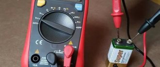
In the first photo the ESR of the capacitor is 0.03 Ohm.
Those who wish to learn more about the operating principle of this device can read the original article on pages 19, 20 of “Radio” No. 8 for 2011.
Variable capacitor
Capacitors whose capacitance can be changed are called variable capacitors.
The simplest variable capacitor has several (less often one) copper or aluminum half-disks, electrically connected to each other and fixedly fixed. Another row of the same half-disks is assembled on a common axis. When this axis is rotated, each of the half-disks mounted on it fits between two fixed half-disks. By turning the axis and thus changing the relative position of the movable and stationary half-disks, we can change the capacitance of the capacitor. Figure 3 shows a diagram of the device and Figure 4 shows a general view of a variable-capacity air capacitor.
Figure 3. Schematic diagram of a variable capacitor
Figure 4. General view of a variable capacitor
Video about the design of a serial variable capacitor:
Video about how you can make a homemade variable capacitor with your own hands:
https://youtube.com/watch?v=DKNN_OA_LYQ
Video about how you can make a homemade variable capacitor with your own hands:
Contents
- 1 Design
- 2 Let's move on to manufacturing the printed circuit board:
- 3 About details
- 4 Scale graduation
- 5 Appearance
- 6 Total
- 7 Files
You may ask, why analog again?
Of course, I have an ESR meter with a digital indicator for a detailed study of large capacitors, but this is not required for operational troubleshooting. In addition, there is a long-standing sympathy for pointer indicators, inherited from the Soviet past, so I wanted something a little vintage. As a result of prototyping, I settled on the well-known ludens
, which allows you to experiment with measuring scales within a wide range. The operating frequency of the generator is 60 kHz. For convenience, the device is designed as a dual-range device – with a narrow and extended scale. The microcircuit can be replaced with TL072.
Calculation using formulas
Calculation of the nominal capacity of an element is required in 2 cases:
- Electronic equipment designers calculate the parameter when creating circuits.
- In the absence of capacitors of suitable power and capacity, craftsmen use element calculations to select from available parts.
RC circuits are calculated using the value of impedance - complex resistance (Z). Ra - current losses due to heating of circuit participants. Ri and Re — take into account the influence of inductance and capacitance of the elements. At the resistor terminals in the RC circuit, the voltage Uр is inversely proportional to Z.
Thermal resistance increases the potential across the load, and reactive resistance decreases. Operating a capacitor at frequencies above resonant frequencies, when the reactive component of the complex resistance increases, leads to voltage losses.
The resonance frequency is inversely proportional to the ability to accumulate charge. From the formula for determining Fр, they calculate what values of C (capacitor capacitance) are required for the operation of the circuit.
To calculate pulse circuits, the circuit time constant is used, which determines the effect of RC on the pulse structure. If the circuit resistance and capacitor charging time are known, the capacitance is calculated using the time constant formula. The truth of the result is influenced by the human factor.
Craftsmen use parallel and series connections of capacitors. The calculation formulas are the reverse of the formulas for resistors.
A series connection makes the capacitance smaller in the connection of elements; a parallel circuit adds up the values.
Why is a high ESR value harmful?
At zero frequency (direct current) and low frequencies, as you remember from the article, the capacitor itself offers great resistance to electric current.
In this case, some parasitic Ohm fractions of the ESR resistance will not affect the parameters of the electrical circuit. All the fun begins when the capacitor operates in high-frequency (HF) circuits. You and I know that a capacitor passes alternating current through itself. And the higher the frequency, the lower the resistance of the capacitor itself. Here's the formula in case you forgot:
where XC is the resistance of the capacitor, Ohm
P is a constant and equals approximately 3.14
F - frequency, measured in Hertz
C - capacitance, measured in Farads
But we didn’t take one thing into account... The resistance of the leads and plates does not change with frequency! So... and if you think about it, it turns out that at an infinite frequency the resistance of the capacitor will be equal to its ESR? It turns out that our capacitor turns into a resistor? How does a resistor behave in an AC circuit? Yes, just like in a DC circuit: it gets hot! Therefore, this resistor will dissipate power P into the environment. And as you remember, power through resistance and current is expressed by the formula:
P=I2xR
Where
I is the current strength, in Amperes
R - ESR resistor resistance, in Ohms
This means that if the ESR is greater, then the power dissipation will also be greater! That is, this resistor will heat up quite well.
Are you catching up on what I’m telling you?