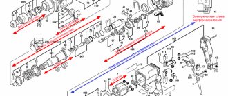
Repair of the mechanical part of the Makita 2450 and 2470 rotary hammer
Any tool repair begins with determining the nature of the malfunction and disassembling it.
The Makita 2450 and 2470 rotary hammer can be repaired by a user who has basic plumbing skills and is familiar with electrical safety requirements.
This article discusses the mechanical part of the Makita rotary hammer, the main faults and how to eliminate them.
Disassembling the mechanical part of the Makita 2470 rotary hammer
To get to the mechanical part of the hammer drill, you need to remove or disassemble the cartridge.
Disassembling the quick-release chuck Place the hammer drill on the back cover of the case on a table surface covered with a clean cloth or paper. Using tweezers or a screwdriver, remove the rubber tip 35, item 1.
Carefully release the ring spring pos. 2, coupling casing pos. 3, steel ring pos. 4. You will reach a steel ball with a diameter of 7 mm, pos. 20.
Now you can remove the housing of the mechanical part. It is black. Using a screwdriver, unscrew the four screws at the end of the housing.
Holding the black body with your right hand, press your thumb on the end of the shaft from which the cartridge was disassembled. The plastic case can be easily removed.
Next you need to remove the gearbox shaft.
To disconnect the mechanical part from the electrical part, you must first remove the electric brushes. Remember! The rotor is held in the lower part of the housing by electric brushes, which must be removed.
After checking that the electric brushes are disconnected from the rotor slats, use a screwdriver to pry the metal housing of the hammer drill at the border of the green plastic housing.
Now we move on to disconnecting the rotor from the mechanical part of the perforator
ra. The rotor is held in the mechanical part by helical gears of the gearbox. If you take the rotor housing in one hand and the mechanical part housing in the other and pull in different directions, rocking, you will separate these two assemblies.
You will get a knot like this in the old grease.
Next, use a hexagon to unscrew two M4×12 bolts, item 43, art. 266273-7 with an internal hex head. Pull out the shaft with intermediate spur gear 10 pos. 80, art. 226399-7. from the inner housing pos. 49, art. 153687-8. Clean the parts from old grease.
You will end up with such a mountain of clean parts.
Now carefully look through the parts, immediately throw away the rubber rings and pick up new ones. Replace defective parts with new ones.
How to properly disassemble a Makita HR2450 rotary hammer?
Looking into the middle, you will see two self-tapping screws 4x60, art. 266334-3, pos. 57, securing the stator to the housing. Unscrew them, remove the plastic stator protection for HR2450, art. 419201-3, pos. 58., free the stator. When you remove the stator, you will see the contacts on the stator and the reverse switch panel.
Thoroughly clean the contacts with sandpaper and treat with solvent or alcohol. Before assembly, bend the contacts so that they fit tightly into each other. Lubricate the contacts with a thin layer of technical Vaseline.
Reassembling the electrical part of the hammer drill is carried out in the reverse order.
Mechanical malfunctions of makita 2450 and makita 2470 rotary hammers
Common mechanical malfunctions of Makita rotary hammers include:
- destruction of the quick release chuck;
- bearing failure;
- damage to the impact mechanism;
- wear of the hammer drill barrel;
- wear of the rubber striker and striker;
- gear failure.
Repair of a hammer drill chuck is carried out to replace the boot and rubber ring, as well as a conical spring and a steel ball that clamps the working tool (drill). This is indicated by the fact that the working tool? namely the drill, is poorly held in the chuck.
The main reason is wear of the steel ball 7.0 pos. 20, art. 216022-2. Ball wear occurs from contamination of the cartridge bore due to dust and dirt getting inside.
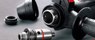
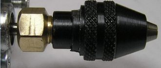
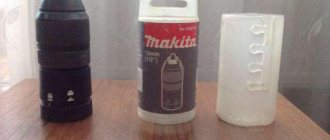
The general view and design of the Makita hammer drill chuck is shown in the photo below.
Repairing a makita 2450 hammer drill chuck with your own hands is easy. The cartridge must be disassembled, freed from old grease, discarded rubber parts, and replaced defective ones.
More complex faults require knowledge of the mechanical structure of the Makita 2450 rotary hammer.
Having determined the nature of the malfunction of the Makita rotary hammer, proceed to disassembling the mechanical part, called the gearbox.
Disassemble the mechanical part according to the attached video. Free it from old grease. Carefully inspect all parts, their integrity, and level of wear. All rubber products require replacement during any disassembly.
Let's consider repairing a hammer drill barrel. Let's analyze the mechanism completely. Video of disassembling, lubricating and assembling a Makita hammer drill
Repair of parts of the Makita 2450 hammer drill barrel
Remember! The rotor is held in the lower part of the housing by electric brushes, which must be removed.
At the next stage, the rotor must be disconnected from the removed mechanism. The rotor is detached from the mechanism simply by pulling it out, since it is held in place by the friction of two helical gears.
It turned out to be such a dirty knot.
Now we need to separate the impact mechanism shaft.
Most often, the rubber rings and the firing pin, pos. 24, compressor spring pos. 18. and cylinder parts.
This is how barrel parts wear out and break down when the tool is used incorrectly.
Let's consider the most complex malfunction - failure of the impact mechanism. Characteristic signs of failure of the impact mechanism are the absence of impact and the unpleasant noise of the rotary hammer operating in the “Impact” mode.
This malfunction is typical for those rotary hammers that, during operation, were strongly pressed against the surface being processed. Having disassembled the gearbox, we remove debris and pieces of foreign objects. We find the faulty part and clean everything of old grease.
Rotary hammer design, assembly diagram and spare parts list
The tool consists of a single-phase motor and rotor. A gear located on the armature shaft is responsible for rotational movements. Between them there are bearings, one of which is “drunk”, it is this that transmits movement to the working parts.
Barrel hammer drill repair
This procedure is no different from repairing a conventional hammer drill. It is worth considering that the motor and shaft are located vertically.
How to fix a rotary hammer with your own hands
The repair procedure at home is the optimal solution and will cost less than the services of service centers. Instrument repair is expensive and it is not a fact that you will find a conscientious repairman. Before you think about how to make a hammer drill, you should acquire the necessary tools and stock up on theoretical knowledge on how to disassemble and assemble a hammer drill. After completing the repair, run it in gentle mode.
Design of Makita 2450 and 2470 rotary hammers
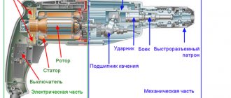
The Makita rotary hammer conventionally consists of electrical and mechanical parts. Moreover, the mechanical unit of the hammer drill is located in a black plastic case, and the electrical part of the hammer drill is hidden under the green plastic case.
The procedure for disassembling the mechanical part of the hammer drill
The mechanical unit is designed to transmit the rotational moment of the shaft to the tool, creating not only torque and a translational impact impulse.
The task of the mechanical unit is to transmit rotation from the rotor to the tool, while providing the tool with longitudinal movement.
Disassembling the hammer drill begins with removing the quick-release chuck.
Quick Release Chuck Parts
Having disassembled the cartridge, unscrew the four screws, pos. 10, fastening the gear housing cover, pos. 14, of the mechanical unit and the hammer housing and, pressing on the end of the hammer shaft, remove the black plastic cover.
Removing the cover of the mechanical unit
To remove the mechanical unit from the green stator housing, you must:
- 1. Unscrew the three screws pos. 70, 75, 76 holding the cover pos. 69 in the hammer handle;
- 2. Remove the cover;
- 3. Having released the springs of the brush holders pos. 63, 66, take out the carbon brushes pos. 65.
Now you can remove the mechanical unit from the stator housing.
Type of mechanical block
Having freed the mechanical unit, it is necessary to disconnect the rotor from it. Rotor pos. is attached to the mechanical block due to the friction of the gear teeth and is pulled out by shaking and disconnecting at the same time.
Disassembling the mechanical block of the shock assembly
The mechanical unit is assembled on the inner housing, pos. 49. To remove the intermediate shaft, you need to unscrew two bolts, pos. 43, at the base of the housing. The intermediate shaft is also fixed with the mode switch lever.
Two words about the mode switch
The Makita 2450, 2470 rotary hammers have a lever that provides the tool with three operating modes. A hammer drill can simply drill, simply chisel, and chisel with simultaneous drilling. The switch lever is placed on the axis of the inner housing and is fixed with a compression spring pos. 85, a washer pos. 87 and a retaining ring pos. 86.
It's time to remove the intermediate shaft.
Disassembling the intermediate shaft
To disassemble the intermediate shaft, use the diagram included in this manual.
Photo of the intermediate shaft diagram indicating the disassembly order
Remove from the shaft pos. 40 in order:
- A). bearing pos. 46 and ring pos. 47;
- b). spur gear pos. 42;
- V). rolling bearing pos. 41;
And on the other side of the shaft, remove:
- G). flat washer 12 pos.35;
- d). bearing 606 pos.36;
- e). retaining ring S-7 pos. 37;
- and). compression spring 7 pos. 38;
- h). clutch coupling pos. 39.
The procedure for disassembling the barrel shaft of the impact mechanism
To disassemble the impact mechanism shaft, it is necessary to pull it out of the inner housing.
It is necessary to remove the cylinder pos. 32, inserted into the internal cavity of the shaft, from the shaft.
The cylinder is very easy to disassemble:
- 1. You need to remove the striker pos. 30 from it;
- 2. The piston hinge pos. 34 is knocked out;
- 3. Remove two flat washers pos. 33, 35.
To disassemble the shaft itself, pos. 21 of the impact mechanism, it is necessary to remove from the side of the cartridge installation shaft:
- — ring spring 28 pos. 16;
- — washer 30 pos. 17;
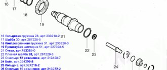
- — compression spring 31 pos. 18;
- — spur gear 51 position 19;
- — steel ball 7.0 pos.20.
And from the side of the internal cavity of the shaft it is necessary to remove:
- — ring spring 28 pos. 29;
- — rubber ring pos. 28;
- — metal ring pos. 27;
- — rubber ring 15 pos. 26;
- — ring 9 pos.25;
- — flat metal washer 28 pos. 22.
Disassembled barrel shaft
Disassembling the electrical part of the Makita 2450, 2470 rotary hammer
The electrical part of the Makita 2450.2470 rotary hammer includes:
- rotor pos.54;
- stator pos.59;
- switch TG813TLB-1 pos.68;
- carbon brushes SV-419 pos.65;
- brush holder pos. 63,66.
To remove the stator, just tap the end of the plastic green case on the stator side with a wooden mallet or block.
But first you need to unscrew two self-tapping screws 4x60 mm pos. 57.
When you frequently tap on the housing, the stator spontaneously protrudes beyond the edges of the housing and is then removed by hand.
How to repair the stator of a Makita hammer drill with your own hands video
| The most detailed information about the certificate can be purchased on our website.attestata.com |
If you have determined that the stator in your hammer drill has failed, but you do not have the funds for a new one, or you want to repair the part yourself, then these instructions are for you. Disassembling a Makita rotary hammer is so simple that repairing makita 2450, 2470 does not pose any particular difficulties. The main thing is to follow the advice given in this article.
Repair of a rotary hammer can be carried out independently by any user who has the skills of a mechanic and knows how to handle diagnostic devices.
Any repair begins with an external inspection of the faulty part. How to find a faulty stator of a Makita 2450 hammer drill? A stator malfunction is most often indicated by the presence of traces of burnt insulation and the appearance of a burning smell. This is the first sign of a short circuit in the stator windings.
But a break can only be determined by testing the winding circuits.
Algorithm for disassembling and manufacturing the stator of a Makita 2450,2470 hammer drill
Here is the sequence for manufacturing the stator of the Makita 2450 rotary hammer:
- Removing the stator assembly from the housing;
- Removing the old winding, determining the winding direction, wire diameter;
- Winding new coils according to the collected data using templates;
- Preparing insulation for new coils;
- Insulation of new coils;
- Installing finished coils into the grooves of the core or winding the coils in the core itself;
- Soldering leads to the ends of the coils;
- Reservation of windings of new coils;
- Impregnation of wound coils;
- Stator assembly.
First things first
Stage
I
Use a wooden hammer or block to disassemble the stator. Tapping the end of the stator housing, remove the stator from the housing. By the way, to get the stator, you need to disconnect the stator housing from the mechanical part housing.
Do not forget to disconnect the stator lead wires from the terminals that go outside in the commutator area. One end is attached to the brush holder, and the other end to the wire supplying 220 V power.
It's time to split it into two halves.
Stage
II
Collapsible stator option
Both halves of the stator are glued together with a thin layer of glue. To separate one from the other, you need to hit the stator core with a mallet.
If you did not receive a dismountable stator, then the wire is dismantled by cutting all the turns at one end with wire cutters. After cutting and disassembling, we take out the wire and measure the diameter of the wire and the number of turns.
To measure the wire diameter, use only a micrometer. First, the wire must be burned in a match flame, the carbon deposits must be wiped off, cooled, and measured.
Most often, the coils are impregnated with an insulating varnish, which does not allow the wires to separate.
Using an industrial hair dryer, heat the coils until they separate into individual wires. You can also heat the impregnated wires in a gas oven over a burner.
When disassembling the stator, it is necessary to take measurements. We need to measure the diameter of the wire, the number of turns in one coil, the percentage of filling of the stator groove, the material from which the wires are made. It is recommended to wind only with copper wires.
Wires are classified by cross-section. Having measured the diameter of the wire, recalculate its cross-section using the formula S=ηr², where r=½d.
And now in clear language: the cross section is equal to 3.14 times half the diameter squared.
What is this whole garden for? If it turns out that you have a wire of a different diameter, then you cannot do without calculations. If there is a thin wire, then winding can be done in 2...3 wires, the main thing is that their total cross-section is no less than the initial one.
If there is a wire of a slightly larger diameter, then you can wind it with it, provided that the filling of the grooves with the old drive was incomplete.
Stage
III
Option for winding a non-separable stator
To wind the stator coils, you need to prepare a wire of a passing diameter, electrical cardboard or pressboard, adhesive tape, and heat-shrinkable casing of the required diameter.
If you have a non-separable stator, then you need to make pressed liners into its grooves, cutting blanks to fit the width of the stator.
The blanks are cut from pressed steel with a width equal to the width of the stator and a length equal to the length of the internal groove. By the way, you need to add 2 mm on each side to the width of the stator. After cutting out the blanks, seal their edges with wide tape. For the stator of a Makita hammer drill, adhesive tape 50 mm wide is suitable.
Place one side of the piece on a strip of tape and cut it. Stick the blanks on the second strip of tape with the same side, but with a different edge. Your task is to protect the edges of the workpieces from gusts during winding.
Making fixture strips
To facilitate the manual winding process, make simple devices, which are strips of soft metal up to 0.8 mm thick. It can be galvanized steel, copper, aluminum. The strips are z-shaped plates 10 mm wide and 70 mm long.
Place a heat-shrink tube on the smaller hook of the device and heat it over a flame, crimp the tip of the plate.
Secure the resulting plates with tape to the stator housing.
Winding process
The wire is prepared, the plates of the device are fixed, data on the number of turns is at hand. Forward!
We place the stator on the knee, wind the end of the wire, put a red heat-shrinkable casing on it (it marks the beginning of the winding), fix the casing on the outside of the stator and start winding. By the way, the color of the cambric can be any, you just need to choose a different color for the beginning and end of the winding.
The winding process involves feeding the wire into the groove with your thumb, inserting the wire over the hook of the device plate, pulling out the wire and inserting it over the hook of the plate on the other side. Most importantly, keep track of the number of wound turns. The winding process is repeated for the second coil.
This is all clearly visible in the video provided.
: Repair of power tools. Rewinding the stator (excitation coils) part 1.
All! The stator is wound. It is necessary to carefully link the windings and perform the reservation.
Stage
IV
Stator winding reservation process
Armoring refers to the binding of stator coils, which protects them from destruction during operation. At high speeds, all parts are affected by various vibrations, which leads to destruction of the integrity of the windings, their friction against each other and disruption of insulation.
It's time to do the impregnation.
Stage
V
The process of impregnation of stator windings
The task of impregnating the stator coils is to obtain a monolithic structure that does not collapse over time from vibration. Before impregnation begins, wooden spacers are inserted inside the stator to press the coils. Work should be carried out carefully and accurately.
Under ideal conditions, a transformer is needed for impregnation. It is recommended to impregnate the coils under voltage so that the wires vibrate and warm up. This allows the impregnation to flow into all the cracks. A small voltage is applied to the windings until vibration occurs. It can be easily detected by placing a screwdriver against the inner surface of the rotor.
Ideally, use a special varnish and apply several layers. You can also use ordinary PF-115 paint for interior painting. Pour 50 g of paint into a separate container, dilute it with solvent to the consistency of water.
Using a syringe, draw up paint and inject it in small portions onto the stator coil until it completely penetrates into the middle of the coil. The stator must be warm and connected to an alternating current source. It is better to use a transformer as a source, the primary winding of which is powered through the LATR.
Don't forget to monitor the stator temperature. To the touch, the hand can hardly withstand the temperature of the case. At higher temperatures, reduce the supply voltage to the transformer using LATR.
The consistency of the paint depends on the diameter of the wires. The thicker the wire, the thicker the paint. Impregnate until paint appears below. Turn the stator over and continue impregnation. Leave the stator under the direction until completely dry.
The stator is impregnated and, after cleaning from traces of paint on the inner surface of the stator, is ready for assembly.
Impregnation and rewinding of the stator
: Stator impregnation. Winding in two wires with a parallel connection.
Now you can begin assembling the Makita rotary hammer. If you think that this is difficult, then it is better to leave the job of rewinding to professionals.
Source: https://lux-standart.ru/articles/kak-otremontirovat-stator-perforatora-makita.php
General characteristics
"Makita 2450" is known among builders and repairmen as a fairly functional professional tool. It is simple, not reliable in operation, has lightness and good balancing. Therefore, the Makita 2450 will last quite a long time. It has a good dust protection system, which makes the equipment durable.
Its popularity is explained by the possibility of holding Makita 2450 on its own. You won't need to spend a lot of money on its maintenance. However, before assembling the Makita 2450 rotary hammer, you should learn everything about the technology for disassembling and repairing it.
Is it worth repairing the hammer drill yourself or is it better to send it to a service center?
Should I repair the device myself or contact a service center? This question interests many people. If you wish, you can easily deal with problems at home by replacing the necessary parts. Service specialists will not always correct the error quickly, but you will have to pay a lot.
In some cases, services only replace them with licensed parts, which also cost a lot, so you’ll have to “fork out for it.” It is best to initially check the device completely yourself, and only if it is impossible to do everything yourself, visit a service center.
The Makita rotary hammer is an excellent device for working at home. If necessary, you can independently cope with the problems that arise, disassemble it and replace the necessary parts.
Specifications
The Makita 2450 hammer drill has a certain set of qualities. The characteristics presented by the manufacturer in the instructions are as follows.
The weight of the tool is only 3.5.4 kg. The drills are secured by the SDS system. The hammer drill is designed for crushing, drilling and non-impact drilling. It has three operating modes. equals one thousand one hundred per minute, and the maximum number of beats. four thousand five hundred per minute. The force of translational motion at maximum is 4.7 J. Maximum:
- for wood. thirty two mm;
- for metal. thirteen mm;
- for concrete. twenty four mm;
- for a hollow crown. fifty four mm.
There are also additional functions for Makita 2450 rotary hammer Characteristics include the presence of a safety clutch, reverse, locking, and additionally electronic speed control.
The power supply network is seven watts. The cable length is four m.
Signs of a fake
Due to the great popularity of the equipment presented, cases of counterfeiting are not uncommon. There are characteristic features that define a fake HR 2450 rotary hammer. This situation includes a short cord (about 0.5 m). The letters on the black clasps of the suitcase are matte on the fake, but on the original. shiny.
In the photo of the hammer drill in the instructions for this product, the background is light gray, almost white. The copy will have a dark, dull color in the background of the image.
If the model HR two thousand four hundred fifty case indicates the manufacturer is Japan, it is not a real instrument. The original says: “Made in PRC”, i.e. “made in China”.
"Makita 2450 " contains a rubberized handle, the serial number is indicated on the busy>. remains the details of the suitcase are also made to contain who own> craftsmanship designation. The fake handle is made not of rubber, but of plastic. This should also be a signal that you need to refuse to purchase such a tool.
Impact shaft assembly
First you need to lubricate the inside of the cylinder, pos. 32, and insert the hammer, pos. 30, into it.
All that remains is to put the lubricated barrel assembly, pos. 21, into place in the inner housing, pos. 49, putting it on the lubricated cylinder, pos. 32. It is recommended to use a special lubricant designed for Makita rotary hammers as lubricants. Lubricants are available in several types: Makita P-08361 and Makita 183477-5 SDS-PLUS. Makita 183477-5 SDS-PLUS lubricant is recommended for the gearbox. Makita 196804-7 lubricant is used for drill shanks.
Lubricants vary in color, but have exactly the same characteristics. What other lubricants are used in the Makita 2450 and 2470 hammer drills?
And here we have an assembled mechanical unit.
Now let's lubricate all parts of the mechanical unit with the recommended lubricant. Here is an example of how to properly apply lubricant to rotating surfaces. Here is another example of generous lubrication of a mechanical unit.
You can't spoil porridge with oil
This way it is also possible to apply lubricant. You can't spoil porridge with oil!
The lubricated mechanical unit must be covered with a black plastic case, pos. 14. Having placed the housing on top of the assembly, press down the housing until the assembly is completely fixed in it. Backwardness Insert four bolts, pos. 10, into the body and tighten. Now it’s time to attach the electric motor rotor to the mechanical part.
Rotor installation
The helical rotor gear is tightly inserted into the body of the mechanical unit and pressed.
It remains to insert four self-tapping screws m4x60 pos.57. and screw them into the electrical unit housing.
Sources:
https://ice-people.ru/perforator/perforator-Makita-2450-sborka-i-razborka-razborka-stvola-perforatora-Makita-2450.html https://sdelalremont.ru/sborka-perforatora-Makita-2450 -i-2470.html
Disassembly diagram
When repairing the presented equipment, the user must be able to disassemble the tool. Hammer assembly diagram
"Makita 2450" has many components and elements. To carry out repairs, you do not need to know all of them. Here are the most basic elements that the diagram represents (“Makita 2450.” The device is very complex).
First. this is a retaining ring. It is involved in the dismantling of the cartridge cover. Next comes the ring locking device. It holds the ball to secure the drill. It is guided by a washer and a conical spring.
The gearbox is connected to the engine by four screws. The circuit contains many rubber parts, which, when worn out, become a common cause of breakdown.
This knowledge is enough to carry out home repairs. Next, you should study the technique of its implementation.
Makita rotary hammer: do-it-yourself repair
Diagnostic technology and troubleshooting are identical to other devices. First, you should disassemble the tool by removing the body, and then remove the old grease and contamination.
It is recommended to replace components that have stopped working. After this, all the components of the mechanism are installed in their original position.
For correct operation, it is recommended to carefully study each repair item. To restore the functionality of the 2010 cartridge, mode switch and housing, perform the following steps:
- Remove the cartridge
- Remove the switch
- Eliminate defects in the interior of the case
- Apply lubricant and replace worn parts
How to disassemble a hammer drill and gearbox?
When disassembling the gearbox, it is recommended to adhere to the following instructions:
- Place the hammer drill on a hard surface, lifting its barrel up
- Using forward movements, pull out the shell, pressing the tool against the table. This position will prevent accidental displacement of the constituent elements
Assembling a Makita hammer drill
After the repair is completed, all removed parts should be returned to their original position. It is recommended to apply a fresh coat of lubricant to all necessary parts.
Before assembly, the body is cleaned with kerosene or gasoline. The cleaned shell is returned to its place. The mode switch should not be located in it.
Makita HR 2450 diagram
The Makita-2450 rotary hammer system consists of many complementary components and a list of spare parts. Among the most significant elements, the features of which should be taken into account during repair work, are the following:
- Ring locking device. It is designed to hold the ball element that secures the drill. The washer and spring guide it
- Retaining ring. This is necessary for correct removal of the cartridge cover.
- Four screws connect the gearbox and motor, eliminating vibration. The circuit contains a large number of rubber components. Often they are the cause of a malfunction.
A description of the mentioned components will be sufficient for high-quality repairs.
Repair
"Makita 2450" can be repaired at home if you have certain knowledge and skills. The technology for inspecting and not replacing parts of the HR two thousand four hundred fifty model is quite simple. Like oil, it involves disassembling the tool, then removing all old grease, dust, and dirt. Damaged nodes are replaced with new ones. Then the parts of the hammer drill are assembled together. It is necessary to study each point of such work. They are performed in the area of the chuck, mode switch, and hammer housing.
To carry out repairs, first remove the cartridge, then the speed switch. After this fact, repairs are carried out inside the case. The lubricant of non-worn rubber elements is replaced.
Assembly procedure for a Makita rotary hammer
The assembly of any mechanism should begin after careful preparation. It is necessary to prepare not only the parts, but also the tools, location, and lubricant.
Tools you can't do without pliers, screwdrivers, a hammer, and a brush for applying lubricant.
What is the assembly diagram for the Makita 2450 and 2470 rotary hammer?
Assembling a Makita rotary hammer with your own hands can only be done if you follow the included instructions.
The task of the assembly process is to replace failed parts with suitable ones and ensure the interchangeability and operability of the tool.
Impact mechanism assembly
How to assemble the impact mechanism of a Makita rotary hammer? The impact mechanism is assembled from two units: a barrel shaft with a spur gear and an intermediate shaft with a rolling bearing. A). A spur gear, pos. 19, is put on the barrel, pos. 21, and pressed by a compression spring, pos. 18. To fix the spring, it is pressed with washer 30, pos. 17, and secured with retaining ring 28, pos. 16. B). To assemble the striker, you need to put ring 9, pos. 25, on the striker shaft, tighten the rubber ring, pos. 26, and press it with the metal ring, pos. 27.
Now we move to the opposite side of the barrel, pos. 21. On the other hand, the inner surface of the barrel must be lubricated with grease and the assembled firing pin, pos. 24, must be inserted inside.
Intermediate shaft and piston assembly
Assembling the intermediate shaft assembly
To assemble the intermediate shaft, you need to put the rolling bearing pos. 41 on the shaft pos. 40 with the teeth to the shaft splines, and put the coupling pos. 39 on the shaft splines.
Translation of translational motion
On the opposite side of the shaft, a helical gear 26 pos. 42, a flat washer 8 pos. 45, a bearing 608zz pos. 46 and a retaining ring 8 pos. 47 are put on. The intermediate shaft is assembled.
Cartridge
When using a flathead screwdriver, the cartridge is disassembled. Repair of rotary hammer " Makita 2450"
» independently start with this element. Squeeze the cartridge cover and remove the rubber boot. Dismantled. Then the cartridge cover and the metal ring are removed. It locks the drill fixation ball in the barrel. It is removed, not a metal washer, but a conical spring can be removed without effort.
The cause of the breakdown is likely to be wear and tear of parts. It is detected if the drill does not lock automatically without releasing the lid. After checking the customer's details, the cause of the breakdown is identified. Old elements are cleaned of dirt not with old lubricant. The ball is thickly treated with new oil. The conical spring is installed with the narrow side facing the resistor.
The guide washer should press it so that it is below the hole in the barrel. Repairing the Makita 2450 rotary hammer from the chuck area requires fixing the ball in the hole. Our parts are assembled in reverse order.
Repair instructions - replacing and connecting a hammer drill button using the example of Makita 2450
Most MAKITA rotary hammers (models HR2020, 2432, 2440, 2440F, 2450, 2455, 2475 and 2641) use a standard TG813TLB-1 series switch.
To inspect and/or replace it, you need to prepare the following tools:
- Phillips screwdriver;
- an awl or a knitting needle.
The procedure for repairing/replacing the power button on a Makita 2450 rotary hammer is as follows:
- Let's disassemble the electrical part of the tool. To do this, use a Phillips screwdriver to unscrew the three mounting screws on the back of the handle and remove the plastic cover.
- Next, you need to fold back the brushes and remove the TG813TLB-1 switch itself.
- To disconnect the switch, you must remove all wires from it. The network wires (brown and blue) are secured with a screw clamp and there are no problems with them - to remove the two wires, you just need to loosen two screws. The remaining wires are attached to self-clamping connectors, and to remove the wire you will need a knitting needle or an awl, which is inserted into a special hole and opens the clamp. In a similar manner, all wires are removed sequentially. To carry out repairs, it will not be superfluous to have a connection diagram for the hammer drill button on hand, so we strongly recommend that before removing the wires, sketch out a schematic diagram or take photos on your smartphone so that no questions arise when connecting the new button.
- Connecting a new button. The wires are simply inserted into the automatic clamps until they stop; the network wires are secured with screws.
- Next, you need to install the button in the mounting hole, return the brushes to their place, install and secure the back cover of the handle with three screws.
VIDEO INSTRUCTIONS» alt=»»>
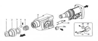
Mode switch
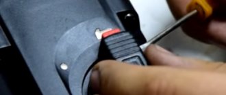
To carry out disassembly, remove the T-shaped latch on the switch handle. Use a 2mm screwdriver. You need to very carefully tighten the tabs of the latch. She is pulled out. The red latch must be held so that it does not fly out under the action of the spring.
After performing these steps, the switch handle should be turned to the extreme left position. So its protrusions will coincide with the grooves of the editor body. The switch is easy to remove. The retainer is removed along with the spring. The rubber ring on the switch handle should be pryed off with a thin screwdriver and not removed. It prevents lubricant from leaking out of the housing.
The assembly diagram of the Makita 2450 rotary hammer in the switch area assumes a certain sequence. Our client is left with the parts and the seating area to be cleaned of old dirt. Thickly lubricate the two metal pins and the rubber ring. It is put on the switch. A spring is inserted into the handle, then a latch. It should not pop out when the latch is installed into the housing.
The switch is then inserted into the gearbox. Here the handle is directed to the sector between the designation of the combined non-strike mode. It won't fit all the way in here. The switch should be turned to the drilling mode not a little further. When you do, you must remember to press the release button so that it does not interfere with movement.
Then turn the switch clockwise and do not fully press the latch.
The procedure for disassembling the hammer drill
Place the hammer drill on a clean surface.
When disassembling the mechanical part of a Makita 2450 or Makita 2470 rotary hammer, you should always remove the mode switch handle.
At the beginning of work, the handle is set to the “Impact” mode (far right position clockwise).
Use a screwdriver to pry up the latch on the handle and remove it.
After removing the latch, the handle is moved to the extreme left position, to the “Drilling” mode.
The handle, clamped with your fingers, is removed from the grooves of the body.
Video instructions for disassembling the mode switch handle of a Makita 2450 hammer drill
Video:
Procedure for setting the mode knob
To install the mode switch into the case, you need to perform some actions: • insert the switch into the “drilling” position into the mounting socket until it clicks; • move the switch counterclockwise to the “blow” position; • turn the switch counterclockwise with a click to the “drilling” position; • insert the spring and the red button; • insert the cover on top until it locks into place. The mode switch is assembled.
At the second stage, you should disassemble the quick-release chuck and repair the hammer drill chuck with your own hands. By the way, the cartridge requires disassembly only for Makita 2470 models. The design of the cartridge is quite simple, and anyone with a little knowledge of metalworking skills can handle its repair.
Switch faults
While familiarizing yourself with the question of how to assemble a Makita 2450, you should find out frequent switch malfunctions. They happen due to wear and tear on the metal pins. And then any of the modes will not turn on. The switch will need to be replaced. This should not be done for which the design is designed to break the landing lugs.
In this case, the rubber ring has worn out and a slight leakage of lubricant occurs. We'll have to replace it.
It happens that the clamp breaks the beak with which it is attached to the cavities of the gearbox. The clamp tabs may be damaged. To avoid all of the above damage, you need to handle the tool carefully.
Procedure for identifying electrical faults
Video: Makita HR 2470 disease The rotary hammer 2470 has finished cutting in. Maintenance tool contacts have burnt
Determining the integrity of the electronic part of a Makita hammer drill. If you set a goal to repair a Makita 2450 or Makita 2470 hammer drill yourself, you need to arm yourself with devices and equipment. Any tester, a set of screwdrivers, keys, a hammer, or a wooden adapter will do. It's great to have a screwdriver with an integrated phase indicator.
You need to take a tester, connect to the ends of the hammer drill plug and press the hammer drill switch. If the tester indicates some resistance, then the power supply circuit of the hammer drill is intact.
If the tester indicates infinity, then the integrity of the circuit is broken and it is necessary to remove the back cover to check the connecting cable and electric brushes of the hammer drill.
The back cover (usually dark in color) of the hammer drill is easily removed; you just need to remove three screws using a screwdriver or a screwdriver.
Remove the cover and use a screwdriver to disconnect the ends of the wires from the electric brushes. Using a tester or a homemade device, also called a “hopper,” determine the integrity of the supply wires and the correct operation of the switch.
A few words about an ordinary control device called “arkashka”. The device consists of an LED or a light bulb from a flashlight, a AA battery and two pieces of wire. The entire electronic circuit of the control device is alternately connected parts. Connect the battery to one end of the LED, or light bulb, and connect the wires to the free ends of the LED and battery. You will get a universal device for checking the integrity of electronic circuits.
Corresponding malfunctions of the Makita 2450 and 2470 rotary hammers Common malfunctions in the electronic part of the Makita 2450 and Makita 2470 rotary hammers:
- fracture of the supply cable at the entry point into the hammer drill;
- breakage of the switch button TG813TLB-1, art. 650508-0, pos. 68.;
- wear of electronic carbon brushes SV-419, art. 191962-4, pos. 65;
- wear of reverse switch contacts;
- wear of rotor bearings: bearing 609LLU, art. 210060-6, pos. 51; bearing 607LLU, art. 211021-9, pos. 56;
- short rotor closure 220-240 V, art. 515668-8, pos. 54;
- breakdown of the stator winding 220-240 V for HR2450, art. 633488-5, pos. 59.
For the start button, use the TG813TLB-1 switch, art. 650508-0; pos. 68.
Replacement of brushes is done when they are completely worn out or have poor contact. This malfunction is detected by strong heating of the points where the electric brushes are installed.
The failure to turn on the hammer drill is caused by abrasion of the contacts on the reverse switch. This type of problem is painfully easy to fix.
Repair of Makita rotary hammer reverse switch
When repairing the reverse switch, you need to disconnect the back cover. Carefully disconnect the wires from the button. Take a close look at the switch.
The upcoming disassembly involves removing the brush holder, having previously freed the brushes themselves. By removing the brush holder, you will get to the reverse switch contacts.
Determine its condition, change contacts if desired.
An additional, often encountered electronic malfunction is poor contact between the stator and the lower contacts of the reverse switch.
Repair of contact between stator and reverse switch
To remove the stator, you need to disconnect the gear housing (dark color) from the stator housing (greenish color).
Remember! In the mechanical part of the rotor, the bearing is pressed by a special ring. Don't lose it when disassembling.
The stator is located in the greenish housing. Having visited the middle, you will see two self-tapping screws 4x60, art. 266334-3, pos. 57, securing the stator to the housing. Unscrew them, remove the plastic stator protection for HR2450, art. 419201-3, pos. 58., release the stator. When you remove the stator, you will see the contacts on the stator and the reverse switch panel.
Carefully clean the contacts with sandpaper and treat with solvent or alcohol.
Before assembly, bend the contacts so that they fit tightly into each other. Lubricate the contacts with a thin layer of technical Vaseline.
Assembling the electronic part of the hammer drill is done in reverse order.
Gear housing
To remove the housing from the gearbox, you need to lift the tool barrel up. The hammer drill should be pressed against the workbench while simultaneously pulling the shell upward. In this situation, our client remains with the parts remaining in their places.
After their inspection, checking that they are not replaced, the gearbox housing is installed in the area. That our client's elements must be presented in their original form. Necessary elements need to be lubricated.
During assembly, the gearbox housing must be cleaned with kerosene or gasoline. Next, the shell is put on the original place. shouldn't be there.
Assembling the impact mechanism shaft
First you need to lubricate the inside of the cylinder, pos. 32, and insert the hammer, pos. 30, into it.
All that remains is to put the lubricated barrel assembly, pos. 21, into place in the inner housing, pos. 49, putting it on the lubricated cylinder, pos. 32. It is recommended to use a special lubricant designed for Makita rotary hammers as lubricants. Lubricants are available in several types: Makita P-08361 and Makita 183477-5 SDS-PLUS. Makita 183477-5 SDS-PLUS lubricant is recommended for the gearbox. Makita lubricant is used for drill shanks .
Lubricants vary in color, but have exactly the same characteristics. What other lubricants are used in the Makita 2450 and 2470 hammer drills?
And here we have the assembled mechanical unit. Video of general disassembly and assembly of the Makita 2450 rotary hammer
Check its performance by rotating the intermediate shaft and monitoring the movement of the piston in the impact mechanism. All!
Now let's lubricate all parts of the mechanical unit with the recommended lubricant. Here is an example of how to properly apply lubricant to rotating surfaces.
Here is another example of generous lubrication of a mechanical unit.
This way it is also possible to apply lubricant. You can't spoil porridge with oil!
The lubricated mechanical unit must be covered with a black plastic case, pos. 14. Having placed the housing on top of the assembly, press down the housing until the assembly is completely fixed in it. Backwardness Insert four bolts, pos. 10, into the body and tighten.
Now it’s time to attach the electric motor rotor to the mechanical part.
READ How to Drill a Concrete Wall Without a Hammer Drill
The helical rotor gear is tightly inserted into the body of the mechanical unit and pressed.
It remains to insert four self-tapping screws m4x60 pos.57. and screw them into the electrical unit housing.
Malfunctions in the gearbox housing
The case of the HR two thousand four model is characterized by high strength; failures here are quite rare. However, it happens that certain troubles occur here. If the housing was received along with the needle bearing, it means that its seating area has become very worn. When this part becomes extremely loose, the housing should be replaced.
Sometimes the place for landing the intermediate shaft is broken. The repair is expected to be similar to the first case.
The gear housing shaft has an oil scraper ring. If it is damaged by construction dust (this happens infrequently) or due to careless actions of a repairman, it is replaced along with the body.
The same procedure is performed if the passage of the mode switch holes fails. The listed types of breakdowns are typical for counterfeit copies.
Consumer Reviews
Among users, opinions about the tool were divided. Disadvantages include overheating and leakage of the Makita 2450. Reviews also make it clear that repairs are carried out by a service center and are not expensive. However, having eliminated the cause of the malfunction yourself, of course, expect normal operation of the tool. Quite often malfunctions occur with hammer drills that have been released recently. But earlier products are known to be of the highest quality. This is due to the appearance of many low-quality fakes, not made using the original technology.
The positive features of the model considered are ease of use, durability and endurance. Similar to oil, according to consumer reviews, quite versatile. The hammer drill is ready to perform the tasks of both a screwdriver and a non-impact wall breaker. Here the tool works with oil filling once every two years without repair. Suitable for both independent use and professional use.
It is noted that this is one of the most inexpensive hammer drills. It's lightweight but powerful. In the matter of purchasing the original, if the user does not handle it normally during operation, the equipment will not work productively for a long time.
By familiarizing yourself with the characteristics and assembly and repair diagrams of the Makita 2450 rotary hammer, you can extend its service life. By performing maintenance without replacing parts yourself, the user will significantly save money. When purchasing, you need to pay attention to the characteristic differences of the original instrument. It will last longer than the fake.
How to repair a Makita HR 2450 rotary hammer if the shock mode has disappeared
As a result, the striker became jammed in the fragments of the collapsed bushing.
The service center advised to replace the barrel completely. It turned out that the bushing is pressed into the barrel at the manufacturer and is not supplied separately. I had to buy a whole new barrel.
In this article, the author will tell you how to get the hammer drill into working condition yourself after this, in general, simple breakdown. If you have the skills to repair power tools and the desire not to pay someone your hard-earned money, then we take the tool and start disassembling the machine.
Tools
You will need two ordinary flathead screwdrivers and one Phillips head screwdriver. One of the flat-head screwdrivers should be thin and narrow, no more than 4 mm wide. You will also need a wire hook to remove the retaining ring. It can be made from a bicycle spoke, the main thing is that the wire is rigid and does not bend easily. You will also need a rubber mallet or wooden mallet.
Work process
Disassembling the hammer drill should begin by removing the protective rubber cap - boot. It can be easily removed, just grab it with your fingers and pull it off the barrel.
Then, by pressing on the plastic cover and squeezing the spring of the SDS + mechanism, remove the retaining ring with a screwdriver.
Using a screwdriver, remove the stopper
The cover is removed from the barrel, and behind it, compressing the spring again, we pull out the retaining ball along with the spring and the figured washer.
Disassembling the SDS mechanism
After which the operating mode switch is disassembled. Under the cover that holds the red locking button, there is a special slot for a screwdriver. By inserting a screwdriver into this groove and prying the cover slightly, first from one edge and then from the other, carefully remove it. You should not apply significant effort here; the cover is still plastic and can break. The red button along with the spring is removed from the switch body, and it is moved to the left all the way, a little beyond the drilling mode. It is from this position that it is removed from the gearbox. For this operation, the switch must be lightly picked up with thin screwdrivers on both sides and removed along with the rubber o-ring.
Read also: The blow on the hammer drill has disappeared
Removing the rotary hammer mode switch
Now the gear box is removed. Using a Phillips screwdriver, unscrew the four bolts connecting the box to the stator housing. Then, holding it with your hand, you need to lightly hit the end of the barrel with a mallet so that the box comes off the gearbox.
Removing the gearbox
After removing the box, remove the barrel from the gearbox. It comes off easily.
Pull the barrel out of the gearbox
Use a rag to remove old grease, wash the barrel with gasoline or kerosene and wipe dry.
So, as mentioned above, it was necessary to completely change the entire barrel. However, this item purchased at the service center turned out to be “as naked as a falcon.” That is, there was absolutely nothing on it and all the parts from the old barrel had to be moved to a new “blank”.
The most difficult operation was removing the firing pin from the barrel body. There are special holes in the barrel body through which the locking ring can be seen. This ring holds the firing pin with rings and rubber dampers in the body seat. Inserting a thin screwdriver into the hole, bend the ring slightly. We do this first on one side and then on the other. The stopper should come out of the groove.
Using two screwdrivers, compress the stopper
Then, from the inside, using a homemade wire hook, we pull the stopper out into the light of day.
Using a wire hook, remove the stopper from the inside.
Next, remove the striker with washers and rubber rings. For assembly, it is necessary to remember or sketch the location of all rings and washers. If something goes wrong, photographs and drawings from the article will help.
Now you need to remove the gear from the shaft. After pressing on the washer and compressing the spring, use a thin screwdriver to remove the retaining ring from the groove. After removing it, remove the washer, spring and gear from the barrel.
Removing the gear wheel
The gear wheel is put on the new barrel and engaged with the splines. Next, a spring with a washer and a stopper are installed on it. You need to insert the locking ring and fix the mechanism in the working position.
To do this, take the barrel in both hands and, resting it in your palms, forcefully compress the spring with your fingers, while simultaneously moving the washer and stopper down. You need to squeeze until the stopper fits into the groove.
Then a firing pin with washers and rubber rings is installed inside the barrel in the order in which it was disassembled. But first you need to pay attention to the condition of the drummer, his appearance.
If the firing pin has gouges and pits after a long period of work or because it was scratched by a broken bushing, then it should be sanded a little.
To do this, it is clamped into the drill chuck and processed with fine-grained emery cloth. But if the irregularities are too large, then the striker will be easier to replace.
Assemble the impact mechanism
It is necessary to lubricate the striker with a special lubricant before installation and then use the lubricant during operation. When inserting a drill into a hammer drill, you need to apply a little lubricant to its shank. This extends the service life of the machine.
Having installed the firing pin mechanism into the barrel, we fix it with a locking ring. Using a screwdriver, we try to move the firing pin on both sides inside the barrel. It should move easily in the channel and not jam.
Assembling a new trunk
We install the assembled barrel into the gearbox housing. Putting it on the cylinder with the piston, we engage it with the drive gear and insert it into the body. All parts should be well lubricated during assembly.
Installing the barrel into the gearbox
Then we install the gearbox, having previously lubricated the needle bearing. Using four bolts, we tighten the box to the stator housing and install the operating mode switch in place. To do this, set it in a position slightly to the left of the drilling mode. We insert the red locking button with a spring and move the switch to the drilling mode. We snap the plastic cover and check the operation of the switch.
Reinstalling the mode switch
Snap the cover of the rotary hammer mode switch
Then, as a final touch, the SDS+ mechanism is assembled. Having installed the mechanism spring, put on the figured washer and insert the ball. Then use a plastic cover to compress the spring of the mechanism and insert the retaining ring. Putting on the rubber boot is no longer difficult.
Compressing the spring with the washer, install the retaining ball
Installing the SDS mechanism
Let's try the hammer drill under load. When the machine is operating, there should be no extraneous noise in the gearbox; the operating mode switch should move easily without jamming. In general, everything should work as before the breakdown.
The author of this article hopes that it will help dear readers understand the repair of a rotary hammer. Any breakdown can be simple if you find its cause. And then everything depends on your skill and diligence.
2 comments on How to repair a Makita HR 2450 hammer drill if the impact mode is lost
In the construction industry, the use of Makita rotary hammers is simply necessary. The importance of this technique is difficult to overestimate; it is indispensable when working with concrete, stone or brick. All particularly durable materials are susceptible to the pressure of this universal tool. In everyday life, Makita rotary hammers are used for drilling holes in concrete and stone, for making openings, recesses, and cable channels in walls and floors.
Device
The Makita rotary hammer has double protective insulation of the motor. Mandatory design elements include a release clutch, which prevents jerking when the drill jams, and electronic speed control. An indicator of corporate style - the tool is equipped with a convenient suitcase for storing the tool.
Most models are equipped with a dust extraction system and are available with a soft rubber pad on the handle. The assortment includes Makita rotary hammers, both with direct and vertical engine.
Principle of operation
It can perform 3 functions: drilling, hammer drilling, chiselling.

